University of Huddersfield Repository Lockwood, Stephen
Design of an obstacle avoidance system for automated guided vehicles Original Citation
Lockwood, Stephen (1992) Design of an obstacle avoidance system for automated guided vehicles. Doctoral thesis, University of Huddersfield.
This version is available at http://eprints.hud.ac.uk/id/eprint/9285/
The University Repository is a digital collection of the research output of the University, available on Open Access. Copyright and Moral Rights for the items on this site are retained by the individual author and/or other copyright owners. Users may access full items free of charge; copies of full text items generally can be reproduced, displayed or performed and given to third parties in any format or medium for personal research or study, educational or notforprofit purposes without prior permission or charge, provided:
• The authors, title and full bibliographic details is credited in any copy; • A hyperlink and/or URL is included for the original metadata page; and • The content is not changed in any way.
For more information, including our policy and submission procedure, please contact the Repository Team at: [email protected].
DESIGN OF AN OBSTACLE
AVOIDANCE SYSTEM FOR
AUTOMATED GUIDED
VEHICLES
Stephen Lockwood .
A thesis submitted to the University of Huddersfield in Partial fulfillment of the
requirements for the degree of Doctor of Philosophy.
October 1992
The University of Huddersfield in collaboration with the Holset Engineering
CONTENTS
Page
ACKNOWLEDGEMENTS
ABSTRACT
LIST OF FIGURES
1 INTRODUCTION
1.1 Automated Guided Vehicles and Factory Automation
11.2 Research Objectives
22 BACKGROUND TO THE RESEARCH
2.1 Summary
62.2 An Introduction to the Guidance Methods A vailable for
Automated Vehicles
62.2.1 Line Following Techniques 7
2.2.1.1 Passive Line Guidance 7
2.2.1.2 Active Line Guidance 8
2.2.1.3 Other Line Following AGV Guidance Methods 8
2.2.2 Free Ranging AGV Navigation 9
2.3 Review of Obstacle Avoidance Research
102.3.1 Architectures For Obstacle Avoidance 11
2.3.2 Sensors and Systems Used For Obstacle Avoidance 11
2.3.2.1 Ultrasonic Systems 12
2.3.2.2 Optical Systems 13
2.3.3 The Need for a New Obstacle Avoidance System 15
3 DESIGN OF A LOW-COST OBSTACLE DETECTION
SYSTEM
3.1 Summary
173.2 The Application of Structured Light for Measurement
and Detection
174 HARDWARE FOR THE OBSTACLE DETECTION AND
EMBEDDED COMPUTER SYSTEM
Page
4.1 Summary
274.2 The CCD Video Camera as a Sensing Element
284.3 Description of the Video Digitising System
284.4 Introduction to the Intel MCS-51 Series Microcontroller
324.5 The Embedded Computer Development System
355 DIGITAL SIGNAL PROCESSING
5.1 Summary
5.2 Digital Filter Design
5.3 Direct Methods for Code Feature Extraction
6 REFLECTED LIGHT CODE RECOGNITION
6.1 Summary
6.2 Light Code Calibration Method
6.3 Light Code Recognition
7 EXPERIMENTAL VEHICLE DESIGN
38 39 46
50 50 53
7.1 Summary
577.2 Review of A GV Drive Configurations
577.3 Overview of the Experimental Vehicle Design
597.4 The HCTL-1100 Microprocessor Based Motor Controller
60 7.4.1 Interface With Intel-8031 Embedded Microcontroller 627.4.2 Types of Output 64
7.4.3 Types of Control 65
7.4.4 HCTL-1100 Digital Motor Controller Tuning 68
8 DEVELOPMENT OF THE OBSTACLE AVOIDANCE
STRATEGY
8.1 Summary
8.2 Obstacle Avoidance Algorithms
Page
8.2.1 'LeftOrRight' Subroutine 73
8.2.2 'TURNAGV'Subroutine 74
8.2.3 • ADV ANCEAGV' Subroutine 76
8.2.4 'RECOVER' Subroutine 78
8.3 Obstacle Avoidance Simulation Package
818.4 Obstacle Avoidance Algorithms Transferred to the Intel
8031 Embedded Microcontroller
84
9 EVALUATION OF THE OBSTACLE AVOIDANCE
SYSTEM
9.1 Summary
879.2 Obstacle Detection System
879.3 Response Time and Real-Time Operation Accuracy and
Repeatability
9010 CONCLUSIONS, LIMITATIONS AND
RECOMMENDATIONS FOR FURTHER WORK
10.1 Conclusions
11010.2 Limitations of the System and Recommendations for
Further Work
113REFERENCES
APPENDICES
A 1 Embedded Computer and Memory Access Buffer Circuit
Diagrams
Al.l Intel 8031 Computer A 1.2 Memory Access Buffers
A2 Pascal Tenninal Emulation Software Listing
A3 Assembler Obstacle Avoidance Software Listing
A4 Motor Control Circuits and HCTL-11 00 Specifications
A4.1 Dual Motor Control CircuitACKNOWLEDGEMENTS
I would like to express my gratitude to all in the School of Engineering at the University of Huddersfield and AMECAS for their help and friendship throughout the research project.
Thanks in particular to Dr Bruce Mehrdadi and Dr Jeff Chandler (Directors of Studies) for their technical input and editorial assistance in the preparation of the thesis. Their relentless encouragement, support and sense of humour have been invaluable. Special thanks are also extended to Dr Mike Freeman (Supervisor) for his technical advice and for proof reading the thesis. His feedback has been most helpful and constructive.
I would also like to express my gratitude to all the Technicians in the Engineering Systems Division for their practical help during the development of the hardware for . the research.
ABSTRACT
Most Industrial Automated Guided Vehicles CAGV s) follow fixed guide paths embedded in the floor or bonded to the floor surface. Whilst reliable in their basic operation, these AGV systems fail if unexpected obstacles are placed in the vehicle path. This can be a problem particularly in semi-automated factories where men and AGVs share the same environment.
The perfonnance of line-guided AGVs may therefore be enhanced with a capability to avoid unexpected obstructions in the guide path. The research described in this thesis addresses some fundamental problems associated with obstacle avoidance for automated vehicles.
A new obstacle avoidance system has been designed which operates by detecting obstacles as they disturb a light pattern projected onto the floor ahead of the AGV. A CCD camera mounted under the front of the vehicle senses obstacles as they emerge into the projection area and reflect the light pattern.
Projected light patterns have been used as an aid to static image analysis in the fields of Computer Aided Design and Engineering. This research extends these ideas in a real-time mobile application. A novel light coding system has been designed which simplifies the image analysis task and allows a low-cost embedded microcontroller to carry out the image processing, code recognition and obstacle avoidance planning functions.
LIST OF FIGURES
eage
2.3.1.1 Subsumption Architecture 11
3.3.1 Projector Lens System 19
3.3.2 Projector - Camera Geometry 20
3.3.3 Projected Light Distortion 20
3.4.1 Projector Masks 21
3.4.2 Obstacle Distorting Projected Dot Grid 21
3.4.3 Distorted Dot Grid After Edge Detection and Thresholding 22 3.4.4 Projected Light Pattern Tends to 'Grow' from the Ground 23
3.4.5 Uniform Vertical Bar Pattern 24
3.4.6 'Letterbox' Viewing Area 24
3.4.7 Projected CCD Elements are Approximately 3mm X 3mm
at a Distance of 1 Metre 25
3.4.8 Vertical Bar Code Projection Mask 26
4.3.1 Composite Video Signal 29
4.3.2 Video Frame Store and Memory Access Buffers 31
4.4.1 Intel 8051 Block Diagram 32
4.4.2 a) Embedded Computer System
b) 8031 Memory Map 34
4.4.3 Method of Digitising Video Image into Two Interleaved
Blocks 35
4.5.1 Development System 36
5.1.1 Obstacle Detection System 38
5.2.1 Grey Level Graph of a Horizontal Strip of the Image 39
5.2.2 Digital Transversal Filter 41
5.2.3 Transversal Filter Frequency Response 41
5.2.4 C-R Filter 43
5.2.5 Frequency Response of a Filter Derived Using Bilinear
Transform Method 43
~
5.2.7 Video Data After Recursive Filtering 46
5.3.1 Typical Filtered Code Pattern Shape 48
5.3.2 Relationship Between Code Features 48
5.3.3 Turning Point Detector Algorithm 49
5.3.4 Video Data and Results fonn Peak Extraction Algorithm 49
6.2.1 Code Calibration Board Must Fill Camera Field of View 52 6.2.2 Flow Chart for Automatic Code Calibration Algorithm 53
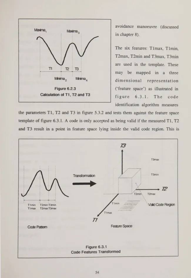
6.2.3 Calculation of T1, T2 and T3 54
6.3.1 Code Features Transfonned 54
6.3.2 Flow Chart of Code Detection Algorithm 55
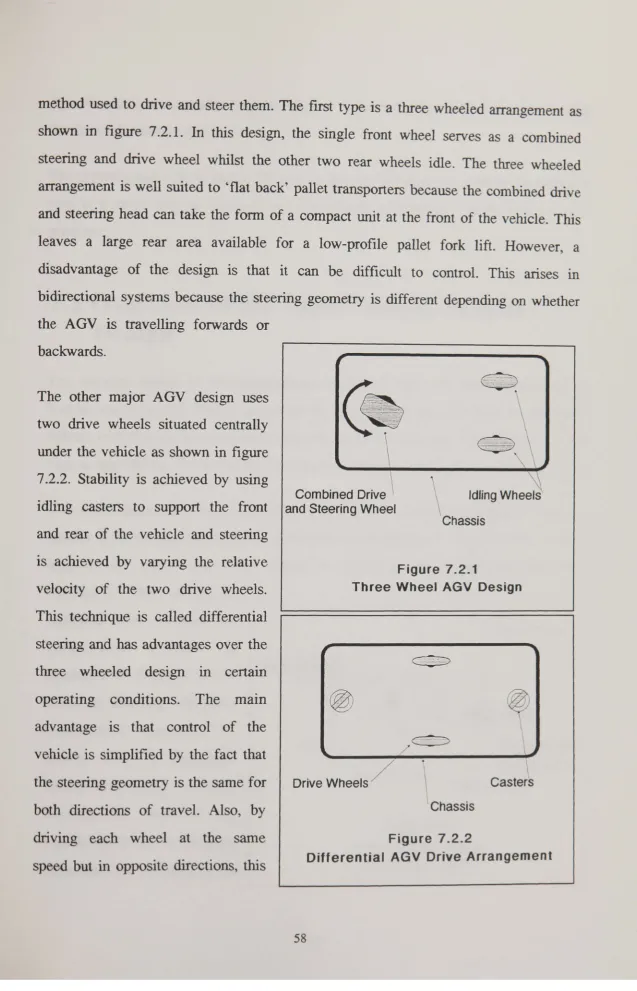
7.2.1 Three Wheel AGV Design 58
7.2.2 Differential AGV Drive Arrangement 58
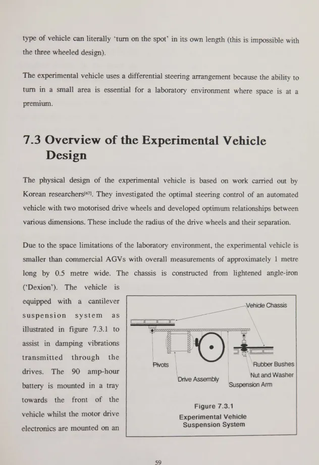
7.3.1 Experimental Vehicle Suspension System 59
7.3.2 Experimental Vehicle 61
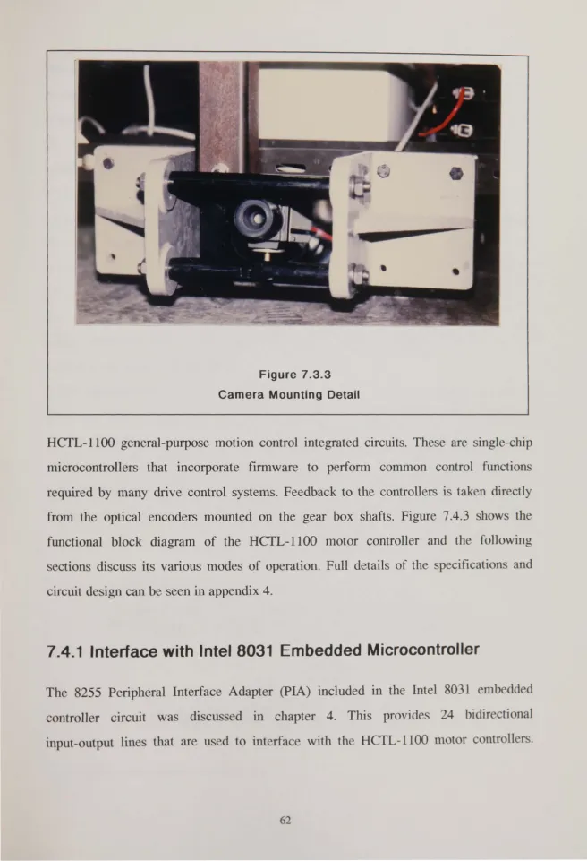
7.3.3 Camera Mounting Detail 62
7.4.1 Experimental Vehicle Drives 63
7.4.2 Experimental Vehicle Drive Block Diagram 63 7.4.3 HCfL-l100 Simplified Functional Block Diagram 64
7.4.2.1 H-Bridge Amplifier 65
7.4.2.2 PWM Motor Controller Output Signals 66
7.4.3.1 HCTL-l100 rapezoidal Profile Mode 68
8.2.1 Automated Heading and Deviation 72
8.2.2.1 Flow Chart for 'TURN' Algorithm 75
8.2.2.2 Flow Chart for 'TEST_TURN' Procedure 75 8.2.3.1 Distance That Automated Vehicle Must Advance to Clear
an Obstacle 76
8.2.3.2 Flow Chart for 'ADVANCE' Procedure 77
8.2.3.3 'ADV ANCE' Procedure Fails if Gap is Too Small for
Automated Vehicle to Negotiate 78
8.2.4.3 8.3.1 8.3.2 9.2.1 9.2.2 9.2.3 9.2.4 9.2.5 9.3.1 9.3.2 9.3.3 9.3.4 9.3.5 9.3.6 9.3.7 9.3.8 9.3.9 9.4.1 9.4.2 9.4.3 9.4.4 9.4.5
Flow Chart for 'RECOVER' Procedure Graphical Elements of Computer Model
a) Single Obstacle Avoidance b) Double Obstacle Avoidance c) A voidance of Three Obstacles
'Test Obstacle', Positioned in Light Pattern Video Camera View of 'Test Obstacle'
Video Camera View of Matt Black Obstacle Video Camera View of a Gloss White Board Typical Obstacles Encountere in Factories
Oscilloscope Trace Showing Access Control Signal Motor Control Signals lllustrating A voidance Response Time
PWM Signal is Smoothed Due to Motor Inductance Subtracted Motor Control Signals During 'TURN' Phase of Obstacle Avoidance
Right Hand Motor Control Signal During 'ADVANCE' Phase of Obstacle A voidance
Moving Obstacle Test
Sequence of Photographs Showing Moving Obstacle Real-Time Test
Photograph Showing Real-Time Path Correction
Photograph Showing System Responding to Two Obstacles Accuracy of Obstacle A voidance System
Vehicle Path Defmed Parallel to Laboratory Wall Photograph Showing Accuracy Test
Photograph Showing Accuracy Test Photograph Showing Repeatability Test
1 INTRODUCTION
1.1 Automated Guided Vehicles and Factory
Automation
The frrst Automated Guided Vehicles (AGVs) were developed in the 19508 by Barrett Electronics of the USA for use in warehouses[1J. These were automated trucks towing trains of carts, guided by a wire system similar to that still used in many installations today.
In 1990, the worldwide AGV market was worth about £2500 million having grown at an annual rate of 12-15% in the previous decade[2]. This growth rate has led to the appearance of AGVs in many guises ranging in complexity from basic units similar to the original Barrett vehicles, to highly 'intelligenf legged automatons designed for such tasks as extra-terrestrial exploration and hazardous environment inspection. In
general, the cost of automated vehicles is reflected in their performance. Complex and expensive vehicles are used in applications where cost is secondary to safety or research, whereas more basic types are employed in warehouses, offices and factories where commercial viability is essential.
Only recently have automated vehicles been used widely in the manufacturing industry. This is partly due to advancing computer technology and its falling cost, and also, partly as a result of changing trends in industrial administration. In particular the adoption of management philosophies such as Just In Time (JIT) coupled with the concept of Flexible Manufacturing Systems (FMS) provide ideal environments for AGVS[3].
requisitions and the fact that work need not be interrupted by rest periods. A further major advantage of automated vehicles as opposed to traditional forms of factory transport such as conveyors and railways, is that they allow more efficient use of the available factory space. This is made possible by the fact that AGV s use unobtrusive or hidden guide-paths that are only apparent when vehicles are actually present. At other times, the thoroughfares can be used by people and other transport. Conveyors and railways on the other hand, require exclusive routes constructed from intrusive steel work and transport equipment.
1.2 Research Objectives
The research presented in this thesis has been carried out m collaboration with AMECAS Ltd., (Advanced Manufacturing Equipment Control and Automation Systems), a trading division of the Holset Engineering Company Ltd., Huddersfield. This division was fonned as a small consultancy following the award winning in-house implementation of a Flexible Manufacturing System at the Holset turbo-charger manufacturing plant in Huddersfield.
The subject of the research was highlighted at an AMECAS Automated Guided Vehicle installation in Doncaster, England. This factory is approximately 1/4 mile long and several hundred metres wide. The AGV system is a wire-guided network of pallet transporters operating along side manual trucks.
---~-~---placed in the AGV guide-path, which in turn leads to automated vehicles becoming stranded. In a factory the size of the Doncaster installatio~ this is a severe problem as the time taken to fmd and travel to stranded vehicles to clear obstructions can be significant. This affects work schedules and hence disrupts production planning.
The problem of obstacle avoidance is associated with the guidance and navigation of automated vehicles and two main solutions are possible:
o
either completely replace the existing AGV system with a new one that has the capability to avoid unexpected obstacles,o
or use an obstacle avoidance system that can be retrofitted to existing vehicles.As yet, no AGV system that can avoid unexpected obstacles is commercially available. Even if such a system did exist, organisations would be unlikely to be persuaded to reinvest heavily in a completely new installation. Rather, they would prefer to upgrade existing vehicles with 'add on' obstacle avoidance units.
Much research has been carried out in the field of obstacle avoidance in attempts to provide commercially viable systems. This is based on a variety of sensor systems and techniques including ultrasound ranging systems, CCD camera systems, laser range fmders and combinations of these. The research presented in this thesis is concerned specifically with the rigorous requirements of the manufacturing industry and with the high demands that such harsh operating environments place on any practicable design. For example, a suitable system should not use moving parts since these would be subject to the eventual ingress of dirt and wear resulting in a degradation of perfonnance. This factor rules out the use of delicate mechanical sensors such as rotating scanners and moving cameras etc.
of its relation to the value of the host vehicle, but also in its operation and maintenance. This implies that the hardware must be relatively simple to install and configure, preferably without the need for special calibration equipment.
A further constraint on the design of a retrofitting obstacle avoidance system is its physical size. Although commercial automated vehicles come in many shapes and sizes, an add-on system must be compact and light-weight enough to be relatively unobtrusive when installed on the host vehicle. This excludes the use of relatively large standard computers and suggests that a design based on compact, single-chip microcontrollers is desirable.
Many automated vehicle systems described in the literature require detailed on-board 'knowledge' of the factory layout in order to perfonn obstacle avoidance tasks. These tend to be application-specific and are not suited to general use. Although obstacle avoidance is often treated as a completely separate issue to that of obstacle detection, this research seeks to combine both detection and avoidance into a practical system that is suitable for general applications.
The objectives discussed in the previous paragraphs have been translated into an innovative obstacle avoidance system. This is based on a novel light pattern projection system and a charged Coupled Device (CCD) imaging system. The light pattern is projected onto the floor ahead of the automated vehicle and is not nonnally visible to the CCD camera mounted under the front of the chassis. However, if an obstacle emerges, the projected light pattern becomes visible to the camera, and the obstruction is detected. The system then controls the vehicle drives to circumnavigate the obstruction and rejoin the original guide path.
smallest detectable object, and the diverse range of obstructions that can be detected. Several examples of the system detecting obstacles typical of those likely to be found
2 BACKGROUND TO THE
RESEARCH
2.1 Summary
This chapter explores the background to the problem of obstacle avoidance. A brief overview of the guidance methods available for Automated Guided Vehicles (AGVs) and mobile robots is presented. Options for solving the obstacle avoidance problem are discussed and a solution is identified for further research. Relevant work by other researchers is reviewed which highlights the key difficulties associated with detecting and negotiating unexpected obstacles. This review confirms that further research work is necessary towards the design of a low-cost, reliable obstacle avoidance system for industrial automated guided vehicles.
2.2 An Introduction to the Guidance Methods
A vailable for Automated Vehicles
AGVs are guided using two basic systems:
o
Line following. This is currently the most common method and has been available since the birth of AGV technology2.2.1 Line Following Techniques
Line following is the most common method of automated vehicle guidance[41, characterised by the fact that AGVs follow paths physically marked on the ground. Either passive or active techniques can be used, depending on the application and the operating environment[5).
2.2.1.1 Passive Line Guidance
Passive systems are common in relatively clean environments where AGV guide lines are not vulnerable to hard wear and dirt. Various methods are used for marking and detecting AGV guide paths depending on the particular design. An excellent review of these and other methods of line guidance has been presented by Premi and Besant[6}.
. White line following systems use sensors consisting of infrared transmitters and receivers to detect the presence and position of white or brightly coloured lines painted or taped onto a dark floor, (or dark lines on light coloured floors). The position of a line in relation to the sensors is used to derive control signals for the AGV drive motors[7].
'Littons Patented Optical System'[l) uses a fluorescent compound to mark AGV guide lines, which is invisible to the human eye under nonnal circumstances. Automated vehicles are equipped with sensing heads consisting of ultra-violet lamps and optical detectors which irradiate the chemical compound and detect its position. Control actions are derived from the sensing heads in a similar fashion to white line following
systems.
to detect the metal tape and derive control signals for the vehicle drives.
2.2.1 .2 Active Line Guidance
Active line guided systems are by far the most commonly used in factories, particularly where the environment is too hostile for systems requiring paint or tape on the floor surface. In active systems, AGV guide paths are marked by embedding large wire loops 1 or 2cm below the floor surface which are driven by AC signals. Automated vehicles equipped with pick-up coils sense the signals, the amplitude of which give a measure of the proximity of the embedded wire and are used to derive steering control. Each embedded guide loop is driven by a different frequency (typically in the range I-15KHz) allowing AGVs to navigate between regions by using band pass filters to select the required loop frequency and reject all others.
2.2.1 .3 Other Line Following AGV Guidance Methods
Other methods of AGV guidance which broadly fall into the category of passive line following have been devised. In particular, Tsukagoshi, Miura and Yamauchi of Japan have described a guidance system which uses ferrite tiles to construct lanes that cross each other in a lattice arrangement[8J• AGV s follow the ferrite lanes using magnetic sensors.
A variation on passive line following has been designed for a clean-room inspection robot[9,lO,1l). This uses spot reflectors embedded in the floor at discrete intervals which
are illuminated using a powerful infrared lamp. Reflections from the spot marks are detected using an infrared
ceo
camera. Steering control is derived from the position of the spot reflections in the CCD image.environments because paint or foil tape can easily become worn away, and white lines or spot reflectors can be obscured by dirt and debris. Also, white line following systems depend on a high contrast between the line and the surrounding floor. However, active embedded wire loops, are not subject to wear and debris and as a result, have been installed widely in the manufacturing industries.
2.2.2 Free Ranging AGV Navigation
Free-ranging automated guided vehicles do not follow physical guide lines. Most systems are based on odometry[12] (or dead reckoning) where vehicle position and heading are derived from incremental encoders coupled to the AGV road wheels and steering gear. Examples of this type of system can be seen in references[13,14,15J. The main disadvantage of AGV navigation using odometry is its inaccuracy[12,161• If the wheel diameters are not accurately matched, the floor not perfectly flat, or the wheels pick up debris, errors accumulate in proportion to the distance travelled and can become unacceptably large. This error may be reduced by combining odometry with other methods of navigation. This approach has been adopted by Stephens Robins and Roberts in their 'TURTLE' system which uses scanning lasers and optical sensors to detect reflectors strategically positioned in known locations around the AGV environment[17]. The angular bearing of the reflectors is used to triangulate the absolute position of the vehicle, and this information is used to correct the accumulated odometry error. Similar triangulation systems have also been designed which use infrared beacons and detectors[18] and ultrasonic transponders and targets[19].
Systems which do not use any fonn of dead reckoning guidance are based on ultrasonic ranging[22) and imaging techniques[23,24,25) which attempt to build range measurement maps of the AGV environment for navigation. Other systems employ optical systems to achieve the same ends and also to recognise previously described objects in the AGV environment[26,27].
Other work on free-ranging AGV navigation systems has tended towards the integration of various sensing techniques in attempts to achieve high reliability and accuracy [28,29,30] •
2.3 Review of Obstacle Avoidance Research
An obvious solution to the problem of obstacle avoidance would be to prevent objects being placed in the path of automated vehicles. However, this undennines a major benefit of AGV systems which is the sharing of common thoroughfares. In an integrated environment, obstacles could only be totally prohibited from the working environment by making the guide path exclusive to A GV s.
Alternatively, the whole wire guidance system could be replaced by a free-ranging scheme with the means to avoid unexpected obstacles. Although considerable research effort continues to be devoted to the design of free-ranging AGV systems the problems which must be overcome to make such systems commercially viable are manifold. These include high cost, high complexity, low speed of operation and low reliability.
2.3.1 Architectures For Obstacle Avoidance
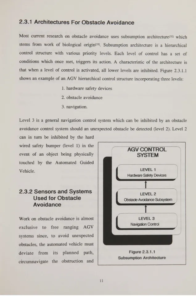
Most current research on obstacle avoidance uses subsumption architecture[32) which stems from work of biological origin[33). Subsumption architecture is a hierarchical control structure with various priority levels. Each level of control has a set of conditions which once met, triggers its action. A characteristic of the architecture is that when a level of control is activated, all lower levels are inhibited. Figure 2.3.1.1 shows an example of an AGV hierarchical control structure incorporating three levels:
1. hardware safety devices
2. obstacle avoidance
3. navigation.
Level 3 is a general navigation control system which can be inhibited by an obstacle avoidance control system should an unexpected obstacle be detected (level 2). Level 2 -can in turn be inhibited by the hard
wired safety bmnper (level 1) in the event of an object being physically touched by the Automated Guided Vehicle.
2.3.2 Sensors and Systems
Used for Obstacle
Avoidance
Work on obstacle avoidance is almost exclusive to free ranging AGV systems since, to avoid unexpected obstacles, the automated vehicle must deviate from its planned path,
AGVCONTROL
SYSTEM
LEVEL 1
Hardware Safety Devices
LEVEL 2
... Obstade Avoidanre Subsystem /
[image:21.694.28.665.42.1014.2]( Navigation Control LEVEL 3
l
~---~Figure 2.3.1.1
either rejoin, or revise the original path. In order to achieve this, the AGV must have some notion of where it is and where it is allowed to go on a new trajectory. This knowledge is usually derived from a software model (or map) of the environment with which the AGV compares its current perceived position[34,35,36J.
Although much work has been carried out on collision free path planning[37,38,39], a large emphasis is now placed on sensing as the key probl em [34,36] and in particular achieving reliable obstacle detection in real-time.
The sensors used in obstacle detection are either acoustic or optical and in some cases both[40J.
2.3.2.1 Ultrasonic Systems
The relatively modest infonnation processing requirements of most ultrasonic ranging systems can be met in real-time but their success is limited by inherent difficulties associated with acoustics[34,35,40,41,42,43,44]. These include:
o
Poor directionality which limits the accuracy in detennining the spatial position of edges to about 10-50 em depending on the distance of the target object from the sensor.o
Inaccuracies in distance measurements can easily occur due to ultrasonic noise from external sources (for example, machine tools, neighbouring sensors, hand tools being used or dropped on the floor etc.) and also by multi-path echoes.o
Specular reflections occur when smooth surfaces are placed at an angle to the sound source[41]. This leads to either the surface not being detected at all or at best, appearing smaller than it actually IS.et al(40) combine ultrasonic techniques with optical methods to navigate a 'health care service' robot. An integrated system has been described by Hollingham[45J, which uses twelve combined SONAR and infrared sensing heads distributed around the periphery of an automated vehicle. Each Transputer based sensing head can be rotated by a small stepper motor in order to scan its locality. A further transputer is used for overall control of the system. Although these sensors may be useful in some automated environments, their cost and delicate nature makes them unsuitable for most factory based AGVs.
2.3.2.2 Optical Systems
Optical sensors used in obstacle avoidance systems range from laser range fmders to CCD cameras and in general, present higher demands in terms of information .processing because of their higher resolution. A system which uses both a colour video camera and a laser range fmder[46) has been used to guide an Autonomous Land Vehicle (AL V) along outdoor roadways[47J • The system uses the colour camera to detect road edges and the laser range fmder to detect objects within the road edges. Image processing is carried out by a powerful host computer and two dedicated digital image processors. Range measurements are processed by a programmable systolic array (the so-called 'warp machine')I48). Although this system is able to operate in real time, (the warp machine has an array of 10 cells, each with a processor operating at 10 million floating point operations per second), the sheer size and cost of the hardware makes it impractical in commercial industrial applications.
An obstacle avoidance system using stereo CCD video cameras has been described in a multi-level architecture for vision based navigation[49). This system employs a powerful
operates in real time, the large multiprocessor work station is not carried on board the mobile robot and the predetermined stereo disparity map of the ground floor is only suitable for laboratory environments. For example, the system would fail if a new pattern was introduced on the floor due to shadows, or spilt liquid, etc.
An alternative obstacle detection system has been described by Takeno and Hachiyama[50], which proposes a new technology for processing stereo images called the 'Laminated Difference Method'. However, this system does not avoid obstacles, it only detects them and under controlled test conditions the system required four seconds to process one pair of images. This performance is too slow for use on industrial A utomated Guided Vehicles.
2.3.3 The Need for a New Obstacle Avoidance System
A cost-effective approach to the obstacle avoidance problem is to design a modular obstacle avoidance sub-system auxiliary to existing AGVs which does not reqUITe modification to existing guidance networks. Enhanced performance of the overall system would be achieved by enabling AGVs to negotiate unexpected obstacles.
AGV users who have invested heavily in line guided navigation systems are unlikely to be persuaded to reinvest in free ranging systems to solve the problem of obstacle avoidance. However, the prospect of improving the efficiency of an existing system by installing a low cost modular obstacle avoidance unit is attractive. Existing conventionally guided AGV systems may not have the "intelligence" to avoid obstacles, but they are reliable if it is accepted that they will fail due to unexpected obstructions. A low cost, modular obstacle avoidance system would not therefore degrade the operation of an existing system; but it would enhance it by allowing AGVs to avoid such objects in the guide path. A completely new, free-ranging system has a high risk of for "teething" problems and may prove less reliable during nonnal, obstacle free navigation.
The review of obstacle avoidance systems presented in this chapter has not revealed a low cost and reliable system which is suitable for integrating into the control hierarchy
of existing AGV navigation systems.
For these reasons, the work presented in this thesis builds on that carried out by Lockwood, Mehrdadi and Chandler[531, and is aimed at the design of a low cost,
modular system which can be retrofitted to existing conventional AGVs.
The single camera system described in the review[51,52) has provided a valuable preface to the study of obstacle avoidance and using it as a starting point, this research is based
o
The geometry of the optical system can be redesigned to enable effective discrimination between true three dimensional objects and two dimensional disturbances on the floor.o
illumination coding techniques can be developed to simplify the image processing task and enable reliable obstacle detection.3 DESIGN OF THE LOW COST
OBSTACLE DETECTION
SYSTEM
3.1 Summary
Light patterns have been used in applications such as metrology, Computer Aided Engineering (CAE) and Computer Aided Design (CAD) to increase the information content in optical systems. However, so called structured light is normally used in static image analysis such'as off-line inspection and 3-D surface measurement.
This chapter reviews relevant research works based on projected light patterns and introduces the concept of extending such systems for mobile use. Sections 3.3, 3.4 and chapters 4,5 and 6 discuss the design of a novel obstacle detection system which is low cost, simple to configure, self-contained and capable of operating in real-time.
3.2 The Application of Structured Light for
Measurement and Detection
Lighting with known geometrical properties that are used to obtain information in illuminated scenes is referred to as 'structured' light[S4]. A 3-D machine perception system which uses a standard slide projector and binary coded slide mask has been describedrs51. The projector illuminates objects with a coded pattern (rather like a 'chess board') and uses a CCD camera and image processing system to determine the range of uniquely coded groups of light points. The surface of objects can be modelled from these range datar56]. Two important features of this system are:
it requires only a single 'snap shot' image to completely analyse a scene. This overcomes a problem called 'smudging' caused by successive frame integration which can occur in mobile systems that need multiple images[551•
o
The hardware is low-cost since a standard slide projector and single camera are used (ie. range measurement can be achieved with a single camera as opposed to triangulation with a stereo pair).However, a major disadvantage of the 3-D machine perception system is the number of computations required. As the authors point out, real-time operation could only be
achieved if the computations were speeded up by a factor of at least 300. This makes the current system unsuitable for automated guided vehicles.
A 3-D measurement system has been designed using a similar projector but with a uniform dot-grid mask rather than a binary codel571 • This system uses a CCD camera which moves laterally on a sliding carriage. Images are acquired with the camera in two positions and range measurements are derived from the relationship of the projected dots in each image (rather like triangulating with stereo cameras). This system has the disadvantages that it uses moving parts which will eventually need service, and the image acquisition and processing procedures are too slow for mobile applications. For example, if the moving camera was mounted on a vehicle which was itself moving, the relationship between a pair of successive images would be extremely complicated unless the precise relative motion of the vehicle was taken into account (the 'smudging' problem described above).
Images are required and image processmg IS carried out off line. Moreover, in
monochrome laser light systems, surfaces with a narrow colour band will only reflect certain colours of light[59]. This problem does not occur when 'white' light, produced for example by tungsten-halogen light sources is used because its spectrum contains components of many colours. Detectable levels of white light are therefore reflected from a wide range of surfaces.
The following design work draws on the research carried out for the machine perception system described earlier[55,56). A novel light pattern has been developed which allows the image processing task to be simplified in order to increase the speed of operation. The light generation and projection system is based on a white light source and adopts a single 'snap-shot' approach suitable for mobile systems.
3.3 Method of Light Generation and Projection
A standard slide projector is used to generate white light illumination. This allows experiments to be easily carried out using projection masks housed in a standard 35mm
photographic slide format. Figure 3.3.1 shows a diagram of the lens system. The geometry of the light projector and CCD camera (described in the next chapter) are illustrated in figure 3.3.2. The aim of the system is to project a light pattern onto the floor ahead of the automated guided vehicle, and detect the distortion of the light pattern caused by objects emerging
Reflector
Ught Source
Slide Mask Lens
\ Lens
.
/
~t
", I \
Side View
----)
Side
View
~ Projector
Camera
-1 metre
--Front View
11 metre
~
- - ( ' I ~
F ron t
[image:30.700.16.669.47.969.2]View
Figure 3.3.2
Projector - Camera Geometry
into the projection area (figure 3.3.3). The type of light pattern and the amount of
information required to reliably detect obstacles determines the speed of operation.
3.4 Design for a
Novel Light
Coding System
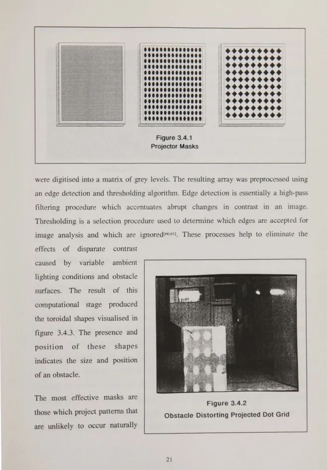
Various projection masks were
used in experiments, including
those illustrated in figure 3.4.1. The
presence of the ' pattern, for
example the dot grid shown in
figure 3.4.2 indicates the position
of an obstacle. In order to detect
the pattern by computer, images
Figure 3.3.3
I • • • • • • • • • • • • • • •
[image:31.704.16.672.39.982.2]1 • • • • • • • • • • • • • • • \1
...
"
• • • • • • • • • • • • • • • 1'
•••••••••••••••
•••••••••••••••
...
'...
,• • • • • • • • • • • • • • • \1
c • • • • • • • • • • • • • • • 1,
• • • • • • • • • • • • • • • 11
•••••••••••• :::
1
i"-
... .
~""'-~~---
-Figure 3.4.1
Projector Masks
( - - - -
-• -•-•-•-•-•-•-•-•
•••••••••
•••••••••
r • • • • • • • • •
~
,... .
~
... .
LI
···
r • • • • • • • • • 1
1 • • • • • • • • • 1
L • • • • • • • • •
!
!
were digitised into a matrix of grey levels. The resulting array was preprocessed using
an edge detection and thresholding algorithm. Edge detection is essentially a high-pass
filtering procedure which accentuates abrupt changes in contrast in an in1age.
Thresholding is a selection procedure used to detennine which edges are accepted for
image analysis and which are ignored[60,611• These processes help to eliminate the
effects of disparate contrast
caused by variable ambient
lighting conditions and obstacle
surfaces. The result of this
computational stage produced
the toroidal shapes visualised in
figure 3.4.3. The presence and
position of these shapes
indicates the size and position
of an obstacle.
The most effective masks are
those which project patterns that
are unlikely to occur naturally
Figure 3.4.2
Figure 3.4.3
Distorted Dot Grid After Edge Detection and Thresholding
(examples of 'naturally'
occurring patterns m this
context are graphics or text on
packing case sides etc). All
the projection masks with
discrete shapes such as
diamonds or dots set in a
predetern1ined grid perfornled
well and obstacles could be
reliably detected. However the
tasks of two-dimensional edge detection and thresholding are
too time consuming to be can-ied out by a low-cost enlbedded conlputer. The design was therefore simplified to
reduce the processing demands whilst maintaining its reliability.
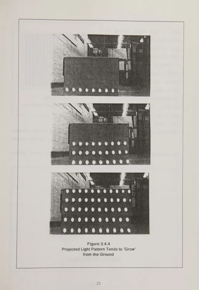
When objects enter the projection area, they disturb the light pattern. Consequently, this distortion appears to 'grow' from the floor and progress vertically in the in1age
(figure 3.4.4). This effect is enhanced by virtue of the projector/camera geometric
relationship as shown in the results presented in later chapters. Vertical bar patterns can be used to enable the image processing task to be reduced from two dimensions to
one, providing that objects are stood on the floor (figure 3.4.5). In order to detect
obstacles, the system needs to process only a narrow horizontal strip of the image
which corresponds to the position where objects begin to distort the light pattern
(figure 3.4.6). However, unifonn bar patterns may become confused with patterns
ocurring on objects which are not obstacles to be avoided. For example unifonn
markings on distant walls or packing cases, or iron railings with uniformly spaced
vertical supports etc. A coded projection mask has been designed to assist in
Figure 3.4.4
Figure 3.4.5
In general, codes with a large
'information' content will result in the
Uniform Vertical Bar Pattern
most reliable obstacle detection. Such
a code could be realised in the form
of a projection mask consisting of
several differently spaced vertical
bars. However, the major
disadvantage of this approach, is that
only large obstacles, disturbing the
whole projected pattern could be
reliably detected. Since the system
must also be able to detect 'thin'
obstacles, several discrete codes across the image must be used and a compromise
between code size and video system resolution must be found.
Several factors affect the design of a compromise light code including the
Obstacle
~1".:'~i:>L--__ 'Letterbox'
Viewing Area
Light Pattern
Figure 3.4.6
CCOARRAY
CCD Elements
I
'
1 metre
FlQure 3.4.7
Approx. 311m
Projected CCO Array
Projected
ceo
Elements Are Approximately3mm X 3mm At a Distance of 1 metre
afonnentioned resolution of the detection system, the 'thinnest' detectable object, and
the required speed of the infonnation extraction algorithm. The central theme of this
design is its low-cost in tenns of both hardware and software, and therefore to maintain
modest memory requirements and high processing speed, images are digitised with a
horizontal resolution of 1:256. This results in a projected resolution of approximately
3mm at a distance of 1m with a viewing angle of 45 degrees using a 12mm camera
lens as shown in figure 3.4.7. A repetitive code similar to that shown in figure 3.4.8
was found to produce reliable results. This code horizontally divides the projection
area into discrete regions. The detection of any complete code indicates the presence of
the projector and camera.
The prototype image processing software includes an algorithm which automatically
identifies the features of the code pattern in use. This allows various masks to be
deployed without the need to specify the physical dimensions of the code. Chapter 5
describes the processing algorithms in detail and the range of suitable masks used in
the course of this research.
Figure 3.4.8
4 HARDWARE FOR THE
OBSTACLE DETECTION AND
EMBEDDED COMPUTER
SYSTEM
4.1 Summary
The hardware for the obstacle avoidance system and the video camera used to detect obstacles are described in this chapter. The advantages of using robust Charged Coupled Device (CCD) image sensors are also highlighted.
The video digitising system is described in section 4.3. This unit takes a standard monochrome composite video signal as input and transforms it via a high-speed analogue to digital converter into a 256 X 256 array of grey levels. This array is in a fOffil which can be processed by the embedded computer system.
In section 4.4, the main features of the Intel MCS-51 series microcontrollers are discussed and the design for the embedded computer system is presented. A shared memory access scheme is described which enables the microcontroller to gain fast access to the digitised video image array.
Finally in section 4.5, the complete embedded software development system is discussed with particular reference to the methods used to design and debug Intel 8051
4.2 The CCD Video Camera
as
a Sensing
Element
The falling cost of CCD arrays together with their improving quality makes them eminently suitable for use in machine vision systems. Also, the robustness of modern CCDs allows their use in systems that may be subject to noise, vibration and other harsh environmental conditions. A low-cost monochrome CCD video camera is used as the detection element of the obstacle avoidance system.
A particular feature of the 1/2" CCD array used in this design is its sensitivity, which enables the camera to operate in light levels down to 0.5 Lux. Conversely, a built in auto-iris adjusts the camera aperture according to the average light intensity falling on the CCD array to prevent saturation in bright ambient light conditions.
The array consists of 370 X 350 light sensitive elements. Since the overall vision system resolution is limited by the Video Frame Store rather than the camera, this CCD camera fulfils the system requirements.
For objects to be avoided without collision, the projected light pattern must produce an image at least as wide as the automated vehicle when it is focused on the floor. A viewing angle of 45 degrees is required for the camera to detect the full width of such an image at a distance of approximately one metre. This is achieved by using a 12mm
wide-angle camera lens.
4.3 Description of the Video Digitising
System
the video signal and storing it in a memory array. Each picture element (or pixel) has a numeric value representing the light intensity, or grey level, of the corresponding point in the video image. Figure 4.3.1 shows the fonn of a composite video signal. As its name suggests, it is an amalgamation of video infonnation and timing wavefonns. As can be seen from the figure, each video line (corresponding to lines on a video monitor or television) takes 64 micro-seconds to update. Standard video frames consist of 625 lines (in the UK), and therefore the complete video image is updated in 50 milliseconds. However, since this update rate can be detected by the human eye and becomes irritating after a short
viewing time, (the television or video screen 'flickers'), a system of 'interlacing' is employed to alleviate the effect. Rather than transmitting . video signals as line 1 through to 625 consecuti vel y, interlacing operates by transmitting odd lines in one screen update and even lines in the next. This effectively reduces the flicker effect and makes television and video screens less irritating to watch.
1 Une of
Video Image
/ Information
~T
i64uS:
/
" I Une Syndlronisation Pulses
Figure 4.3.1
Composite Video Signal
If the full resolution of 625 video lines are not required, the video interlacing need not be used. For example if a video processing system has a vertical resolution of 256 lines, it is unimportant whether odd or even lines are used and therefore complete screen updates can take place in 25 milliseconds.
mentioned this would result in a video memory array being completely updated in
either 25 or 50 milliseconds depending on whether interlacing was used or not. High speed analogue to digital conversion, (with a sampling rate in the order of 8-10 megahertz) is required to achieve such real time video digitisation. Some video digitising systems overcome this need for high speed conversion by taking one sample from each video line per screen update. However, for a digiti.sed image resolution of 256 X 256 pixels, this requires 256 screen updates. A system of this type will therefore take 6.4 seconds to completely digitise a video frame. This is an unacceptable perfonnance for most robotic systems.
The monochrome Video Frame Store described here[62] operates in real-time with a resolution of 256 X 256 picture elements. Each pixel has a grey level value in the range 0-255. Interlacing is not used and therefore complete video images are digitised in 25 milliseconds.
Figure 4.3.2 shows the block diagram of the video frame store. An 8-bit analogue to digital converter was used in the system for the following reasons:
o
The obstacle avoidance system is based on a low-cost 8-bit embedded microcontroller. Extra hardware and software overheads would be necessary for a word length greater than 8 bits and the operating speed of the system would be reduced.o
The cost of greater resolution analogue to digital converters thatoperate at speeds fast enough to digitise video signals in real-time is high.
o
The limitations of 8-bit grey level and spatial resolution can be effectively overcome using digital filters implemented insoftware (see chapter 5).
the frame store writes these digitised samples to the correct addresses in the 64K video memory array via the memory access buffers shown in the diagram. (These are discussed in section 4.4).
In the prototype video frame store, a digital to analogue converter and associated control circuits are included to enable digitised images to be displayed on a standard composite video monitor. The digitised video data written to the memory array is constantly reread and converted back to an analogue signal. This signal is scaled and clamped to the correct voltage levels and synchronisation waveforms are mixed with it to reconstitute a composite video signal. The integrity of the video memory can be
checked using this facility since a read or write failure will be reflected in the reconstituted video display. Also, the results of intermediate stages of video processing may be viewed as an aid to development. This section of the video frame store would be omitted from the fInished product.
CCO Camera Composite Video Monitor
Control
Embedded
~:.-=--:...:....=....:=-=--, .. Computer
Figure 4.3.2
Video Frame Store and
64K Video Memory
DATA
ADDR
4.4 Introduction to the Intel MCS-51 Series
Microcontroller
The MCS-51 senes Intel microcontrollers consist of a family of 8 bit single-chip
computers which are ideal for embedded applications. Figure 4.4.1 shows the block
diagram of the original member of the family, the 8051. The main features of this
integrated circuit are:
o
8 bit Central Processing Unit optimised for control applications.o
Boolean processing (ie. single bit) capabilities.o
32 bidirectional and individually addressable I/O lines.o
128 bytes of on-chip data RAM.o
Two fully programmable 16 bit timer / counters.o
Full duplex Universal Asynchronous Receiver Transmitter.o
5 source interrupt structure with 2 priority levels.External Interrupts
4K bytes ROM
r---I
: 64K bytes :
i External
I
: Program
i Memory
I
: Address
I
: Space I
I ______ ---~
Figure 4.4.1
Timer 1
Timer 0
~---i ! 64K bytes :
External i Data 1
: Memory 1
: Address :
I
: Space I
I I
l ______________ _
Intel 8051 Block Diagram
~Ul CD_
o
On chip clock oscillator.o
4K bytes on-chip program memory (one time only programmable ROM).o
64K bytes program memory address space. D 64K bytes data memory address space.The second member of the family is the Intel 8031. This chip has all the features of the 8051 except for the 4K bytes on-chip ROM. Instead, the 8031 fetches all instructions from external program memory.
Other members of the family include 80CXX CMOS versions of the chip featuring low power consumption and 83CXX versions which incorporate facilities including a watch-dog timer and power down mode of operation.
In this work a single 8031 microcontroller is used for both obstacle detection and obstacle avoidance control. Figure 4.4.2.a shows the block diagram of the embedded computer system incorporating the Intel 8031 and associated interface circuitry and figure 4.4.2.b shows the data-memory map of the 8031 along with its allocation in this system. An Intel 8255 Peripheral Interface Adapter (PIA) is used for interfacing with the AGV main drive motor controllers discussed in later chapters. The Intel 8031 directly addresses the video image memory array directly in a shared access arrangement.
Shared access is achieved by incorporating memory access buffers in the circuits that enable the 8031 microcontroller to access the video data memory at high speed. No modification to the video frame store circuits is necessary since the memory access buffer circuit replaces the video RAM chips and uses the same connections.
To Video Frame Store Data 64K
Memory
FFFFH
Video Memory
Not Used
Upper 32K
\
__________
--' I
8000H-8002H
ff) 8255 PIA I
~
7FFFh
~
e
'E
Intel 8031 AS232-TTL
0 Protocol Video
()
~ Converter Memory
0
(5 (shared
::l: Lower 32K
I
Iwith
0 video
~ frame
Eprom store)
(Emulator) To IBM Compatible
OOOOH
(a) Embedded Computer System (b) 8031 Memory Map
Figure 4.4.2
space for other devices such as the 8255 PIA and other possible system expansions.
Furthennore, the speed constraints on the system are critical since digitising a video
line into 256 pixels in real-time requires a write operation to the video memory
approximately every 256 nanoseconds. These problems are overcome by using two
interleaved 32 Kbyte 'pages' of memory rather than a single 64 Kbyte block. The
organisation of these memory pages leaves 32 Kbytes Intel 8031 address space
available and also relieves the system timing requirements. The two 32 Kbyte memory
blocks are configured as shown in figure 4.4.3.
The two memory pages appear in the lower half of the 8031 data memory address
map. Access to each 32K block is controlled via an additional control signal derived
from one of the microcontroller input/output port pins. Each 32K memory is accessed
once per two video-analogue to digital conversions effectively doubling the required
The video frame store continually
updates the video memory array so
that the latest possible CCD image
infonnation is always available.
When the 8031 microcontroller
requues access to the video
memory to perform obstacle
detection processIng, it switches
the memory access buffers to
suspend video updating (ie. it
'freezes' the image) to gain access
to the memory.
Full details of the memory access
a=RAMPAGEA
" b=RAMPAGEB
Pidure Elements
Figure 4.4.3
Method of Digitising Video Image In Two Interleaved Blocks
buffers and embedded computer circuits are included in appendix 1.
4.5 The Embedded Computer Development
System
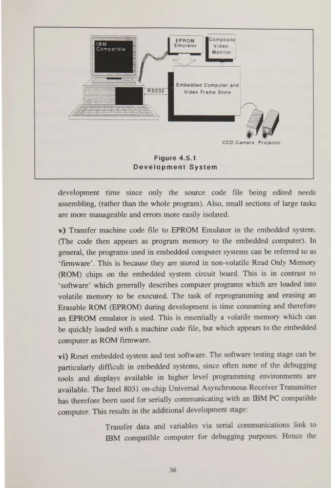
Figure 4.5.1 shows the schematic diagram of the embedded computer development
system. The program development cycle consists of the following stages:
i) Task evaluation and specification, (ie. what is required of the program and
how will it be achieved).
ii) Write program source code in 8051 assembler language mnemonics. The
source code consists of text files that can be generated using any text editor.
iii) Assemble source code files to produce 8051 machine code object files. This
stage converts assembler mnemonics to Intel 8051 machine operation codes.
iv) Link object files to produce a single contiguous machine code file. Most
EPROM
Emulator Video Monitor
Embedded Computer and Video Frame Store
[image:46.702.10.656.48.999.2]CCO Camera Projector
Figure 4.5.1
Development System
development time smce only the source code file being edited needs assembling, (rather than the whole program). Also, small sections of large tasks are more manageable and errors more easily isolated.
v) Transfer machine code file to EPROM Emulator in the embedded system. (The code then appears as program memory to the embedded computer). In
general, the programs used in embedded computer systems can be referred to as 'fmnware'. This is because they are stored in non-volatile Read Only Memory (ROM) chips on the embedded system circuit board. This is in contrast to 'software' which generally describes computer programs which are loaded into volatile memory to be executed. The task of reprogramming and erasing an Erasable ROM (EPROM) during development is time consuming and therefore an EPROM emulator is used. This is essentially a volatile memory which can be quickly loaded with a machine code file, but which appears to the embedded computer as ROM firmware.
vi) Reset embedded system and test software. The software testing stage can be particularly difficult in embedded systems, since often none of the debugging tools and displays available in higher level programming environments are available. The Intel 8031 on-chip Universal Asynchronous Receiver Transmitter has therefore been used for serially communicating with an liM PC compatible
computer. This results in the additional development stage:
full power of the IBM compatible computer keyboard and display can be used to aid software development.
In some complicated algorithms (for example the obstacle avoidance procedures described later) the task of coding software directly into 8051 assembler is extremely difficult. In these cases models were first developed in Turbo PASCAL and then simplified for conversion to Intel 8051 source code. Again full use was made of the fmal stage in the above development cycle to interface the PASCAL and machine code software as it evolved.
5 DIGITAL SIGNAL
PROCESSING
5.1 Summary
Coded patterns occur in the CCD
video image due to the reflection of
projected light patterns from objects
on the floor ahead of the AGV. This
chapter describes the techniques
used to recover this code
infonnation from digitised video
data.
Figure 5.1.1 shows the block
diagram for the obstacle detection
system. With reference to the
figure, the obstacle detection system
operates on digitised video data and
is divided into three sections:
~ Transversal Recursive
Video - - . . . Fi Iter f - - Fi Iter
>--Peak
L..., Detector
f--Pattern
r
R . I--Code Positions~ . . ec_og.nt.so.-'r
Feature
'- Extractor
L
Code Codef---l
Measurement~. Parameters
Figure 5.1.1
Obstacle Detection System
o
A preprocessing stage which employs two digital filters that are described in section 5.2.o
Peak detection and feature extraction stages which isolatepotential code parameters (detailed in section 5.3).
o
Code measurement and recognition stages which are discussed fully in chapter 6The digital filters described in section 5.2 perform a vital role in maximising the
stage to 'clean up' the video signal and act as a coarse 'sieve' for the data. So called
'direct methods' (see section 5.3) are then applied to extract potential code features
from the preprocessed video data. Finally, valid codes are detected using a 'decision
theoretic', pattern recognition technique described in chapter 6.
5.2 Digital Filter Design
Since the low cost video frame store and associated hardware are relatively limited in
tenns of resolution and grey level accuracy, the system is subject to a certain amount
of quantisation error. This manifests itself as wide band noise superimposed on the
digitised video signal. The digital filters described in this section are designed to
reduce this effect.
Figure 5.2.1 shows a video-still together with a typically noisy graphical representation
of a single horizontal line scanned across the lower image(!).
Figure 5.2.1
Digital filters were chosen in preference to analogue filters in this work since after digitising, video data are in a highly suitable fonn for processing using discrete digital methods.
Dedicated digital signal processors were considered for the task of digital filtering. Although the operating speed of such devices is high, a comparison between dedicated signal processors and microcomputers showed the former to be relatively expensive with a low degree of flexibility. On the other hand, Signal processing using micro-computers is cost effective, flexible and requires a simple hardware designf631. Hence, with the special design considerations described next, the required digital filters were implemented in software on the Intel 8031 microcontroller.
The design of tightly specified fmite impulse response filters for microprocessors is a complex task which is exacerbated by the restriction of using assembler language. This is due to the need for numerical accuracy. Insufficient accuracy in both the storage of numbers and calculations can compound the quantisation errors in the system and in some cases render the filters unstable[641.
The following design work shows that acceptable digital filter characteristics can be
achieved using exactly specified integer arithmetic. This fact makes such filters simple
to implement with high execution speeds.
The fITSt stage of processing uses a non-recursive transversal filter to average eight horizontal lines of the image in the "letter box' view described in section 3.4. The operation of this filter is shown in figure 5.2.2. A special case of such a filter and one which does not require floating point arithmetic is when all the weightings aO ... am are equal. This is similar to a moving average filter[641 and is simple to implement in
horizontal lines. The effect of this operation IS to enhance the
influence of persistent vertical patterns in the image array whilst reducing the effect of spurious noise or ~snow'. The choice of the
number of lines to average depends
on both the minimum height of the object being detected and the required algorithm execution speed. Whilst a large number of lines
results ill greater enhancement of
vertical patterns, if the object in the
x(n)
x(n-1)
1
x(rHll)T T T T
I
I
ee
I y(n)
~---~+
Rgure 5.2.2
Digital Transversal Riter
. image is not tall enough to produce persistent vertical patterns, the process will fail. Conversely, if too few lines are averaged, the process has a reduced immunity to noise.
In order to maximise the execution speed of the digital transversal filter, only ~powers
of two' horizontal lines were considered (ie. 2, 4, 8, 16 etc.). These values enable division calculations to be carried out efficiently using machine code arithmetic shift
Ampli tude
Frequenclo:!
Figur e 5.2.3
right operations. Experiments showed that eight horizontal lines of the video image provides reliable obstacle detection combined with high execution speed. In the prototype design, this corresponds to a physical horizontal strip approximately 20mm when projected onto an object one metre in front of the camera.
The resultant array of 256 averaged elements is further processed to remove high frequency co