2016 International Conference on Manufacturing Science and Information Engineering (ICMSIE 2016) ISBN: 978-1-60595-325-0
The Design of the Site Dynamic Balance Test
System Based on ARM
YULIANG CONG, YUYING LIAN and HUAIHAI XU
ABSTRACT
The problem of the dynamic balance has always been a research hot spot. People hope to have faster processing speed, higher precision, more portable test system, to continuously improve the measurement system. This paper discusses the dynamic balancing test system design, including hardware and software two aspects.
Through the hardware part, we can have the amplitude and the phase of the unbalanced component shown on the screen; through the software part, we can change the parameter freely to handle the different problem of the different rotor.
I.INTRODUCTION
With the development of society, the mechanical rotor has been throughout all areas of life and production. The rotor balancing problems have been the focus of the researchers. The precise detection of unbalancing problems not only can eliminate the security risks but also bring huge economic benefits.
Dynamic balancing algorithm can be summarized into two major categories: the modal balancing method and the influence coefficient method. The modal balancing method is only studied in theory, because this method is obtained by the analysis of the imbalance, so the field dynamic balance theory cannot be applied in practice. The general expression of influence coefficient method is proposed based on least square method, afterwards, scholars proposed the weighted least squared method. Many researchers have used this method to solve practical problems and to control error in the range of allowable. In this paper, the algorithm of unbalanced signal processing is also based on the weighted least square method.
To solve the problem of the dynamic balance, this paper applied the weighted least squared method to process the unbalance component and design a set of ARM processor as the core of the system circuit to have the touch screen software operation interface, which can get the good human-computer interaction.
II. ALGORITHM
A. Unbalanced Vibration Signal
By the signal theory we can know that any signal can be represented as the form of a sine wave superposition. The superposition of the components includes the DC component, the fundamental component, the harmonic component and the noise component. Therefore, the unbalanced vibration signal is expressed as the following expression through our analysis:
0
2
sin sin
n
i i
i
e t E E t E i t n t
In which, E0 is the DC component, Esin
t
is the fundamentalcomponent, 2
sin n
i i
i
E i t
is the harmonic component and n t
is the noisecomponent. Esin
t
is as the same frequency as the unbalance components, and the amplitude and phase of the fundamental component is corresponding to the amplitude and phase of the unbalance component. Therefore, we calculate the amplitude E and phase of the fundamental component in order to extract the amplitude and phase of the imbalance component.B. Unbalanced Signal Extraction Technique Least Square Method
The principle of least squares is a standard approach in regression analysis to the approximate solution of over determined systems, according to the principle of the minimum error principle, to make the assumption that the error of the measured value and the real value is the least, which is to make the fitting of the relationship between the value of the mathematical expression and the true value is better. In front we have discussed that any signal can be expressed as a superposition of the form of a sinusoidal signal, so we can put the unbalanced vibration signal of the sensor to be synthesized in type (1) form:
1
1
sin(2 )
n
j i i
i
y b Y n f t
According to the error theory, we hope to have the least square of the fitting signal and the original signal is the least, that is:
1 1 2 2 2
1
3 3 4 4
, , ,
( )
, , ,
n
j j
i i
j j
Y Y
y y
Y Y
(2)
According to the type (2), we know that we can use the differential in mathematics, and the fitting signal Y to calculate the partial derivative of the variables, and to make the results as 0. As we can see, the amount of computation is large, and needs high requirements for the processor. But according to this method, the proposed algorithm is relatively simple in design of peripheral signal processing circuit. The error of the algorithm can be controlled within the allowable range. For portable field dynamic balancing system, it is very practical.
C. Unbalanced Singnal In Practice
Because the existing dynamic balance measuring instrument is limited by the speed of the rotor, in order to improve the accuracy of measurement, it is necessary to measure repeatedly and calculate the amplitude and phase of unbalance based on the relatively error theory. In order to overcome the above problems, an improved algorithm based on the weighted least squared method is proposed. According to the signal correlation theory, any signal can be expressed as the form of the superposition of sinusoidal signal, but because the measurement algorithm is affected by the rotor speed, so the weight of each component is added to the rotor speed:
1 1
sin(2 )
n
j i i
i
y b Y n f t
(3)
In which, Yi, i is the amplitude and phase of the frequency multiplication
signal of the radial vibration of the rotor, j is the weights for the jth time , b is
DC component.
1) Determine the weigh value
The vibration frequency and vibration amplitude increase with the increase of the speed of the rotor, and the variation law is approximately linear. When the
rotor is repeatedly detected, the assumption that the speed range is
1, 2
, thenumber of rational speed is n, then the weight j can be expressed as follows:
j 2 1 j
n
We can see, j is related to the value of the speed and the number of sampling
points, and the value of j is close to 1. So we have:
2 1 1 1 sin(2 ) n j i i i j n
y b Y n f t
(5)
2) Extraction of the amplitude and phase of vibration signal
We know that, the vibration signal caused by the unbalance of the rotor is composed of the fundamental frequency component and the harmonic component of the sinusoidal signal. The harmonic components of the vibration signal caused by the unbalance of the rotor are relatively small and negligible. Therefore, the four order components of the vibration signal are only obtained, we have:
1 1 1 2 1 2
3 1 3 4 1 4
sin(2 ) sin(2 )
sin(2 ) sin(2 ) ( )
j
j j
y b Y f t Y f t
Y f t Y f t G t
(6)
According to the theory of least square error theory, we know, to make the approximation of the signal with the high degree and the original signal fitting, the sum of squares of the difference between the two has to be the least, according to the principle of matrix theory, the parameters of the related position of the type (6), type (7) can be obtained:
1 1 2 2 2
1
3 3 4 4
, , , ( ) , , , n j j i i j j Y Y y y Y Y
(7)In which, n is the sampling point of the vibration signal, we can simplify type (6) as follow:
1 1 2 2 3 3 4 4
5 5 6 6 7 7 8 8
y a x a x a x a x
a x a x a x a x
(8)
So we have:
1 2 3 4 2 1
5 6 7 8
, , , ( ) , , , n i i
a a a a
y y
a a a a
(9)III. SIMULATION
Experimental results:
First, we set the speed range of the rotor (600rad/s, 1200rad/s), the speed of each test was 600rad/s, 700rad/s, 800rad/s, 900rad/s, 1000rad/s, 1100rad/s. The rotor rotation frequency is 40Hz, the noise is white noise, the power is 0.03, according to type (3) we can get the expression of the simulation signal:
0.5 8sin(2 40 / 2) 2sin(4 40 / 3)
sin(6 40 / 4) 0.5sin(8 40 / 2) ( )
i i
i i
y t t
t t G t
(10)
In order to observe the simulation results, here we take the sampling frequency of 5000Hz, to determine the corresponding weights and the corresponding signal simulation, the specific process is as follows:
When the speed of 600rad/s, 700rad/s, 800rad/s, 900rad/s, 1000rad/s, 1100rad/s, the corresponding weights were:
1 1.17
,2 1.14,3 1.12,4 1.11,5 1.10,6 1.09
The corresponding fitting signal frequency domain is as Figure1~6.
According to the above simulation results we can see, although the weights of different speed are different, but the amplitude and phase of the fundamental frequency signal are close to each other.
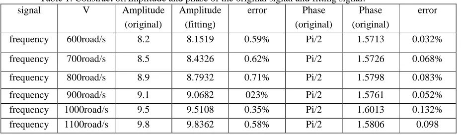
The relationship between weight and speed of type (10) and different speed can be used to calculate the amplitude and phase of the corresponding vibration signal, and the corresponding simulation results are shown in Table 3.1.
[image:5.612.93.557.516.654.2]From Table 1, we can see that the error of the amplitude and phase of the simulated signal and the original signal are small at the six different speed, so this method can be used to detect the rotor at different speeds, and the amplitude and phase of the measured unbalance are basically the same at different speeds.
Table 1. Constract ofAmplitude and phase of the original signal and fitting signal.
signal V Amplitude
(original)
Amplitude (fitting)
error Phase
(original)
Phase (original)
error
frequency 600road/s 8.2 8.1519 0.59% Pi/2 1.5713 0.032%
frequency 700road/s 8.5 8.4326 0.62% Pi/2 1.5726 0.068%
frequency 800road/s 8.9 8.7932 0.71% Pi/2 1.5798 0.083%
frequency 900road/s 9.1 9.0682 023% Pi/2 1.5761 0.052%
frequency 1000road/s 9.5 9.5108 0.35% Pi/2 1.6013 0.132%
IV. SYSTEMDESIGN
General structure of the system:
The dynamic balance test system is a test of the vibration signal caused by the unbalance of the rotor. The vibration signal is changed into electrical signals (such as voltage and current), which can be measured by the sensor, and then through a series of hardware circuits. Finally, extract useful information of the signal, i.e. phase and amplitude.
The general dynamic balance test system is a double side correction of the rotor, that is, detect at the two support points on the installation of sensors, and a photoelectric sensor to test the rotor speed, the system's hardware components, such as figure 7.
Signal conditioning circuit
displacement sensor
rotor
Photoelectric sensor
integral circuit
Amplification / attenuation circuit
Pre-process circuit A/D
micro proce ssor
Display
Vabration Simulation signal
A/D
USB InterfaceDisplay ARM9TDMS3C2440
JTAG Serial port Keyboard
mouse
Touch screen
HOST
Figure 1. Hardware component diagram of Figure 2. Overall system architecture diagram. dynamic balance test system
A. Hardware System Design
Vibration analog signal enters from the processor ADC interface for A/D conversion, extracting amplitude and phase of the corresponding digital signal. Touch screen create a good human-computer interaction interface, ARM processor external touch screen allows the operator to set the signal acquisition parameters, and through the touch screen we can observe the corresponding test results, which is the amplitude and phase of the unbalanced signal, through the serial port, USB interface, JTAG interface, we can achieve data transmission, online debugging and information printing.
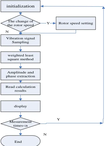
B. Software System Design
[image:6.612.108.495.264.391.2]above procedures to produce a system software design flow chart shown in Figure 9.
initialization
Vibration signal Sampling
weighted least square method
Amplitude and phase extraction
Read calculation results
display
Rotor speed setting The change of
the rotor speed
Mesurement times<n
Y
N
Y
End
[image:7.612.198.378.127.378.2]N
Figure 3. Software flow chart.
V. CONCLUSION
In this paper, a general dynamic balancing system is designed for the improvement of the locale dynamic balancing instrument. The system mainly consists of two parts, hardware and software. The hardware and software of the system are accomplished by the analysis of each part of the frame. And through analysis and discussion above the locale dynamic balancing technology and dynamic balance theory, the improved algorithm of weighted least square method is proposed. The algorithm is simulated and the simulation results are analyzed.
REFERENCES
1. Parkinson A G. Balancing of Rotating Machinery[J]. Proceedings of the Institution of Mechanical Engineers.Part C:Mechanical Engineering Science,1991,205(1):53-56. 2. Bishop R E D, Gladwell G M L. The Vibration and Balancing of an Unbalanced Flexible
Rotor[J]. Journal of Mechanical Engineering Science,1959,1(1):66-77.
3. Zhou S, Shi J. Active Balancing and Vibration Control of Rotating Machinery A Survey[J]. Shock and Vibration Digest,2001,33(5):361-371.
4. Young J.S. Development of an automatic balancing system for a small statellite attitude control simulator[J]. Master thesis, Utah StateUniversity, 1998.