WIRELESS CONTROL QUADCOPTER WITH STEREO CAMERA AND SELF-BALANCING SYSTEM
MONGKHUN QETKEAW A/L VECHIAN
A project report submitted in partial
Fulfillment of the requirement for the award of the Degree of Master of Electrical Engineering
Faculty of Electrical and Electronics Engineering Universiti Tun Hussein Onn Malaysia
ABSTRACT
This research focused on develops a remotely operated Quadcopter system. The
ABSTRAK
Penyelidikan ini memberi tumpuan membangunkan sistem Quadcopter yang dikendali secara jarak jauh. Graphical user interface (GUI) digunakan untuk mengawal Quadcopter. Komunikasi antara GUI dan Quadcopter menggunakan alat komunikasi tanpa wayar yang dikenali sebagai Xbee. Pengimbangan Quadcopter dikawal oleh FY90 dan IMU 5DOF. Quadcopter dilengkapi dengan sensor ultrasonic bagi tujuan pendaratan. Semua isyarat daripada sensor diproses oleh
mikropengawal Arduino Uno. Output dari mikropengawal Arduino Uno digunakan untuk mengawal pergerakan Quadcopter. GUI direka dengan menggunakan perisian
CONTENTS
TITLE i
DECLARATION ii
ABSTACT iii
CONTENTS v
LIST OF TABLES viii
LIST OF FIGURES ix
CHAPTER 1 PROJECT INTRODUCTION 1
1.1 Introduction 1
1.2 Problem statements 2
1.3 Project objectives 2
1.4 Project scopes / constrains 2
1.5 Report outline 3
CHAPTER 2 LITERATURE REVIEW 4
2.1 Introduction 4
2.2 Technology development 4
CHAPTER 3 METHODOLOGY 9
3.1 Introduction 9
3.2 Flow chart 9
3.3.1 Take-off and landing motion 12
3.3.2 Forward and backward motion 14
3.3.3 Left and right motion 15
3.3.4 Hovering or static position 16
3.4 Quadcopter mathematical modeling 16
3.5 Component requirement 19
3.6 Schematic diagram and PCB layout 20
3.7 Quadcopter body design 26
3.7.1 Frame work 26
3.7.2 Mass properties of design Quadcopter frame 28
3.8 Quadcopter graphical user interface (GUI) 29
3.8.1 GUI comport setting 30
3.8.2 Throttle control GUI 31
3.8.3 Elevator control GUI 31
3.8.4 Aileron control GUI 32
3.8.5 Rudder control GUI 33
3.9 XBee wireless radio communication 34
3.9.1 XBee module interface with Arduino Uno 35
3.9.2 Setting source and destination address 36
of XBee
3.10 FY90Q Quadcopter controller 39
3.11 Closed loop control FY90Q throttle input for 40
Quadcopter altitude
CHAPTER 4 RESULT AND ANALYSIS 42
4.1 Introduction 42
4.2 Weight analysis of Quadcopter 42
4.3 Arduino Uno pulse position modulation (PPM) 45
signal generate
4.4 Electronics speed control (ESC) PPM minimum 48
and maximum point calibration
4.5 Quadcopter hover ability 49
4.6 Quadcopter power consumption 52
4.6.1 Test of Quadcopter operated time for 53
different throttle range
4.7 Quadcopter pitch and roll axis disturbance test 54
4.7.1 Quadcopter roll axis disturbance test result and 56
analysis
4.7.2 Quadcopter pitch axis disturbance test result and 60
Analysis
4.7.3 Summarize of roll and pitch load disturbance test 64
4.8 Quadcopter wireless camera analysis 64
CHAPTER 5 CONCLUSION 66
5.1 Conclusion 66
5.2 Recommendation for further development 66
LIST OF TABLES
2.1 Summarize and comparison of Quadcopter previous work 8
3.1 Component and Arduino Uno pin assign 23
3.2 XBee address setting parameter 37
4.1 Quadcopter major parts weight 44
4.2 Battery specification 52
4.3 Testing result of throttle range versus operate time 53
4.4 Disturbance test parameter 56
LIST OF FIGURES
2.1 Result of 3-DOF attitude control 4
2.2 Altitude control of Quadcopter 5
2.3 System structure 6
2.4 Control diagram using Fuzzy controller 6
2.5 Simulink model of PID controller 7
2.6 Test result of the Flying Experiment 7
3.1 Flow chart of Quadcopter design 10
3.2 Pitch direction of Quadcopter 11
3.3 Roll direction of Quadcopter 11
3.4 Yaw direction of Quadcopter 12
3.5 Take-off motion 13
3.6 Landing motion 13
3.7 Forward motion 14
3.8 Backward motion 14
3.9 Right motion 15
3.10 Left motion 15
3.11 Schematic of Quadcopter 16
3.12 Angle movement of Quadcopter 18
3.14 Flow chart of circuit board design 21
3.15 Schematic of Arduino Uno pin attach by ISIS 22
3.16 Schematic of brushless motor pin and led pin attach by ISIS 22
3.17 Schematic of IMU 5DOF and ping sensor pin attach by ISIS 23
3.18 Schematic of XBee pin attach by ISIS 23
3.19 PCB layout of circuit board using Proteus ARES (Top side) 24
3.20 PCB layout of circuit board using Proteus ARES (Bottom side) 25
3.21 Fabricated PCB with component 25
3.22 Sketch of Quadcopter top plate with dimension in millimeter 26
3.23 Sketch of Quadcopter bottom plate with dimension in millimeter 27
3.24 Sketch of Quadcopter top and bottom plate connected 27
3.25 Sketch of Quadcopter side view 28
3.26 Sketch of Quadcopter frame with top cover 28
3.27 Mass properties report of design frame by Solid Works 29
3.28 Quadcopter graphical user interface (GUI) 30
3.29 Com port setting 30
3.30 Throttle control GUI for attitude movement 31
3.31 Elevator control GUI for forward and backward movement 32
3.32 Aileron control GUI for forward and backward movement 33
3.33 Rudder control GUI for forward and backward movement 34
3.34 XBee series 1 module 35
3.35 XBee Starter Kit 35
3.37 X-CTU software 36
3.38 X-CTU basic command for XBee address setting 37
3.39 XBee module 1 (Control Station) address setting 38
3.40 XBee module 2 (Quadcopter) address setting 38
3.41 FY90Q module 39
3.42 Block Diagram of Complementary Filter 39
3.43 Block diagram of Quadcopter altitude Closed loop control 40
3.44 Wireless camera 40
3.45 Wireless camera receiver 41
4.1 Motor performance at voltage source 11.1V 43
4.2 Weight of Quadcopter by mass properties simulation 44
4.3 Measurement of actual weight of the Quadcopter 45
4.4(a) Minimum generated PPM signal (500 microseconds) 46
4.4(b) Minimum generated PPM signal (500 microseconds) 46
4.5(a) Maximum generated PPM signal (2400 microseconds) 47
4.5(b) Maximum generated PPM signal (2400 microseconds) 47
4.6 Minimum ESC detected PPM signal (900 microseconds) 48
4.7 Maximum ESC detected PPM signal (2000 microseconds) 49
4.8 Arduino code for hover ability test 50
4.9 Quadcopter hover ability test platform 51
4.10 Quadcopter lifted completely from ground 51
4.11 Brushless motor specification 52
4.13 Matlab code for read real time data from Arduino 55
4.14 Quadcopter roll axis disturbance test platform 55
4.15 Quadcopter pitch axis disturbance test platform 56
4.16 Roll disturbance test response (no disturbance) 57
4.17 Roll disturbance test response (100g disturbance) 58
4.18 Roll disturbance test response (150g disturbance) 58
4.19 Roll disturbance test response (200g disturbance) 59
4.20 Roll disturbance test response (250g disturbance) 59
4.21 Roll disturbance test response (300g disturbance) 60
4.22 Pitch disturbance test response (no disturbance) 61
4.23 Pitch disturbance test response (100g disturbance) 61
4.24 Pitch disturbance test response (150g disturbance) 62
4.25 Pitch disturbance test response (200g disturbance) 62
4.26 Pitch disturbance test response (250g disturbance) 63
4.27 Pitch disturbance test response (300g disturbance) 63
4.28 Video display by obstacle (without obstacle) 65
CHAPTER 1
INTRODUCTION
1.1 Introduction
Research and development of unmanned aerial vehicle (UAV) and micro aerial vehicle (MAV) are getting high encouragement nowadays, since the application of UAV and MAV can apply to variety of area such as rescue mission, military, film making, agriculture and others. In U.S. Coast Guard maritime search and rescue mission, UAV that attached with infrared cameras assist the mission to search the target [1].
Quadcopter or quad rotor aircraft is one of the UAV that are major focuses of active researches in recent years. Compare to terrestrial mobile robot that often possible to limit the model to kinematics, Quadcopter required dynamics in order to account for gravity effect and aerodynamic forces [2]. Quadcopter operated by thrust that produce by four motors that attached to it body. It has four input force and six output states (x, y, z, θ, ψ, ω) and it is an under-actuated system, since this enable Quadcopter to carry more load [3].
1.2 Problem statement
The main problem in Quadcopter is the balancing and stability system. Most of Quadcopter will be unbalance and lost stability in case there are disturbance direct on it such as wind. In this research, to solve above problem the full system of Quadcopter is design and construct. Graphical user interface (GUI) is design in this research to make control task of Quadcopter easier.
1.3 Project objectives
The objectives of this project are:
(a) To design Quadcopter that can control wireless base on computer. (b) To design graphical user interface to communicate and control
Quadcopter.
(c) To equip Quadcopter with stereo camera to display video. (d) To test the performance of designed Quadcopter.
1.4 Project scopes / constrains
The scopes include the weather condition, distance and space:
(a) Quadcopter only can operate in sunny day or dry condition.
(b) Quadcopter operate distance not more than 100m in eye sight from the wireless receiver.
(c) Quadcopter is control by Arduino base microcontroller.
1.5 Report outline
CHAPTER 2
LITERATURE REVIEW
2.1 Introduction
In order to run “Wireless Control Quadcopter with Stereo Camera and Self Balancing
System” research, several theoretical and techniques are need review through previous
related research report. The review includes the technology development and control
method that used in Quadcopter.
2.2 Technology development
Park et.al. (2001) studied on the 3-DOF attitude control free-flying vehicle. The
characteristic to be heavily coupled with inputs and outputs, and the serious
non-linearity appear in the flying vehicle and due to this non-linear control, multi variable
control or optimal control for the attitude control of flying Quadcopter. This research
[image:15.595.188.453.560.705.2]result is illustrated in Figure 2.1.
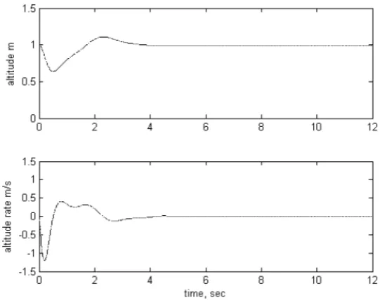
Ashfaq Ahmad Mian et.al.(2007) developed of nonlinear model and nonlinear
control strategy for a 6-DOF Quadcopter aerial robot. The nonlinear model of
Quadcopter aerial robot is based on Newton-Euler formalism. Model derivation
comprises determining equations of motion of the Quadcopter in three dimensions and
seeking to approximate actuation forces through modelling of the aerodynamic
coefficients and electric motor dynamics. The respective of the applied control is
[image:16.595.181.452.247.461.2]described in Figure 2.2.
Figure 2.2: Altitude control of Quadcopter
Achtelik et.al. (2009) done research on control of Quadcopter by visual tracking
using stereo camera. The motion of a Quadcopter is control based on visual feedback
and measurement of inertial sensor. In this research, active markers were finely
designed to improve visibility under various perspectives. The structure of Quadcopter
Figure 2.3: System structure
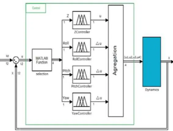
Santos et.al. (2010) works on intelligent fuzzy controller of Quadcopter.A fuzzy
control is designed and implemented to control a simulation model of the Quadcopter.
The inputs are the desired values of the height, roll, pitch and yaw. The outputs are the
power of each of the four rotors that is necessary to reach the specifications. Simulation
results prove the efficiency of this intelligent control strategy is acceptable. Figure 2.4
represented the fuzzy controller in this research.
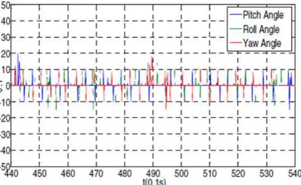
[image:17.595.172.456.485.700.2]Jun Li et.al. (2011) is done research to analyze the dynamic characteristics and
PID controller performance of a Quadcopter. This paper is describe the architecture of
Quadcopter and analyzes the dynamic model on it. Besides that, this paper also designs
a controller which aim to regulate the posture (position and orientation) of the 6-DOF
Quadcopter. Simulink model of PID controller and flying result done in this research
are described in Figure 2.5 and 2.6. Summarizing and comparison of all previous work
[image:18.595.160.476.261.419.2]of Quadcopter are listed in Table 2.1.
Figure 2.5: Simulink model of PID controller
[image:18.595.164.471.473.662.2]Table 2.1: Summarize and comparison of Quadcopter previous work.
No. Research Title Advantages Disadvantages
1. 3-DOF attitude
control free-flying vehicle
Simple and basic of controller design.
Limited degree of freedom (Only 3-DOF applies).
2. Nonlinear model and
nonlinear control strategy for a 6-DOF Quadcopter aerial robot
Compensate the initial error, stabilize roll, pitch and yaw angles and maintain them at zero.
Only design for balancing during hover position of Quadcopter
3. Control of
Quadcopter by visual tracking using stereo camera
The tracking system is highly transportable, easy to set up.
Sensitive to light and not suitable to use at high illumination area
4. Intelligent fuzzy
controller of Quadcopter
Fuzzy controller has fast dynamic response and small overshoot
Controller design is too complex
5. Analyze the dynamic
characteristics and PID controller performance of a Quadcopter
CHAPTER 3
METHODOLOGY
3.1 Introduction
This chapter will divide into two phases. The first phase is understanding the
Quadcopter structure and it basic mathematical modeling. The last phase is deals with
design and construction of the Quadcopter. It will be built by splitting the design into
different component whereby each component will be tested to ensure its working
properly. This step is to minimize the risk of accidents which will lead to increasing
number of component cost.
3.2 Flow chart
Designs of Quadcopter are divided into two stages that is part design in first stage and
full interface at second stage. Flow chart of Quadcopter design is described in Figure
Figure 3.1: Flow chart of Quadcopter design Yes END Quadcopter can maintain it balancing? No Quadcopter can perform design motion?
FY-90Q and IMU 5-DOF
programming
No
Yes
Apply some disturbance during Quadcopter hovering ESC and Brushless
motor programming in first stage
Test GUI communication with controller board
START
Assembly all parts on Quadcopter body
Test runs brushless motor by GUI
3.3 Quadcopter movement mechanism
Quadcopter can described as a small vehicle with four propellers attached to rotor
located at the cross frame. This aim for fixed pitch rotors are use to control the vehicle
motion. The speeds of these four rotors are independent. By independent, pitch, roll and
yaw attitude of the vehicle can be control easily. Pitch, roll and yaw attitude off
[image:22.595.151.490.255.429.2]Quadcopter are shown in Figure 3.2, 3.3 and 3.4.
Figure 3.2: Pitch direction of Quadcopter
[image:22.595.152.486.498.685.2]Figure 3.4: Yaw direction of Quadcopter
Quadcopter have four inputs force and basically the thrust that produced by the
propeller that connect to the rotor. The motion of Quadcopter can control through fix
the thrust that produced. These thrust can control by the speed of each rotor.
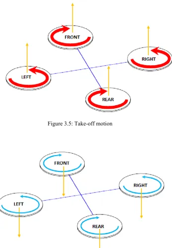
3.3.1 Take-off and landing motion mechanism
Take-off is movement of Quadcopter that lift up from ground to hover position and
landing position is versa of take-off position. Take-off (landing) motion is control by
increasing (decreasing) speed of four rotors simultaneously which means changing the
vertical motion. Figure 3.5 and 3.6 illustrated the take-off and landing motion of
Figure 3.5: Take-off motion
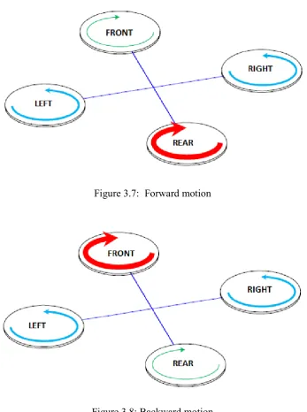
3.3.2 Forward and backward motion
Forward (backward) motion is control by increasing (decreasing) speed of rear (front)
rotor. Decreasing (increasing) rear (front) rotor speed simultaneously will affect the
pitch angle of the Quadcopter. The forward and backward motions of Quadcopter are
represented in Figure 3.7 and 3.8 respectively.
[image:25.595.146.494.241.708.2]Figure 3.7: Forward motion
3.3.3 Left and right motion
For left and right motion, it can control by changing the yaw angle of Quadcopter. Yaw
angle can control by increasing (decreasing) counter-clockwise rotors speed while
decreasing (increasing) clockwise rotor speed. Figure 3.9 and 3.10 show the right and
left motion of Quadcopter.
[image:26.595.154.506.245.716.2]Figure 3.9: Right motion
3.3.4 Hovering or static position
The hovering or static position of Quadcopter is done by two pairs of rotors are rotating
in clockwise and counter-clockwise respectively with same speed. By two rotors
rotating in clockwise and counter-clockwise position, the total sum of reaction torque is
zero and this allowed Quadcopter in hovering position.
3.4 Quadcopter mathematical modeling
The schematic movement of Quadcopter is represented in Figure 3.11 and based on this
[image:27.595.153.482.343.635.2]schematic, the Quadcopter mathematical modeling is derived as below[10]:
Figure 3.11: Schematic of Quadcopter
Where,
Th1= thrust generated by front motor
Th2= thrust generated by rear motor
Th3= thrust generated by right motor
Th4= thrust generated by left motor
m = mass of Quadcopter
g = the acceleration of gravity
l = the half length of the Quadcopter
x, y, z = three position
θ, ɸ, ψ = three Euler angles representing pitch, roll, and yaw
The dynamics formulation of Quadcopter moving from landing position to a fixed point
in the space is given as:
= ɸɸ ɸɸ+ − ɸɸ ɸɸɸ− + ɸɸ
−
(3.1)
Where,
R = matrix transformation
= Sin (θ), ɸ= Sin (ɸ), = Sin (ψ) = Cos (θ), ɸ= Cos (ɸ), = Cos (ψ)
By applying the force and moment balance laws, the Quadcopter motion equation are
given in Equation (3.2) till (3.4) and Pythagoras theorem is computed as Figure 3.12.
= u1 (CosɸSinθCosψ + SinɸSin) – K1ẋ/m (3.2)
= u1 (SinɸSinθCosψ + CosɸSin) – K2ẏ/m (3.3)
= u1 (CosɸCosψ) -g – K3/m (3.4)
Where,
Figure 3.12: Angle movement of Quadcopter
The angle ɸd and ψd in Figure 3.12 are determined using Equation (3.5) and (3.6)
respectively.
ɸd = tan (3.5)
ψd = tan !" !# (3.6)
Quadcopter have four controller input forces U1, U2, U3, and U4 that will affects
certain side of Quadcopter. U1 affect the attitude of the Quadcopter, U2 affects the
rotation in roll angle, U3 affects the pitch angle and U4 control the yaw angle. To control
the Quadcopter movement is done by controlling each input variable. The equations of
U1 = (Th1 + Th2 + Th3 + Th4) / m
U2 = l (-Th1-Th2+Th3+Th4) / I1
U3 = l (-Th1+Th2+Th3-Th4) / I2
U4 = l (Th1+Th2+Th3+Th4) / I3 (3.7)
Where,
Thi = thrust generated by four motor
C = the force to moment scaling factor
Ii = the moment of inertia with respect to the axes
Then the second derivatives of each angle are:
= U2 – lK4/I1 (3.8)
= U3– lK5/I2 (3.9)
ɸ = U1– lK6ɸ/I3 (3.10)
3.5 Component requirement
Component that required is divided into two parts that are hardware and
software. Figure 3.13 shows the major component of Quadcopter that are used. FY-90Q
is applied as auto balance controller of Quadcopter based on input signal from IMU
5-DOF sensor. The signal produced by Arduino Uno to control four brushless motor of
Quadcopter through FY-90Q. The Quadcopter body must be rigid and light weight in
order to minimize the Quadcopter weigh. For software part, Microsoft visual basic 2008
Figure 3.13: Major components of Quadcopter
3.6 Schematic diagram and PCB layout
The schematic diagram of the circuit in this project is design using PROTUES software.
Certain procedure has to be done to ensure the circuit is satisfying the needs of this
project. The circuit board includes controller circuit, PPM signal pin, IMU 5-DOF
sensor, PING sensor pin and XBee wireless port. This circuit board is designed to attach
Figure 3.14: Flow chart of circuit board design
Figure 3.15 till 3.17 described the connection of Arduino Uno board and its pin
assignments as listed in Table 3.1. The schematic electronics circuit is design using
Proteus Ares software. For simple form the circuitry are drawn in double layer PCB.
Figure 3.19 and 3.20 illustrated the PCB layout and Figure 3.21 shows the completed
Figure 3.15: Schematic of Arduino Uno pin attach by ISIS
[image:33.595.194.442.384.614.2]Figure 3.17: Schematic of IMU 5DOF and ping sensor pin attach by ISIS
Figure 3.18: Schematic of XBee pin attach by ISIS
Table 3.1: Component and Arduino Uno pin assign.
PIN ARDUINO UNO PIN XBEE 1 3.3V
2 0
3 1
10 GND
PING Sensor 1 GND
2 5V
3 7
IMU 5DOF 1 3.3V
2 GND
3 A3
4 A4
5 -
6 -
7 A2
8 A1
[image:34.595.150.490.503.705.2]Table 3.1: (continued).
[image:35.595.152.492.128.224.2]PPM 1 - 3 PPM 2 - 5 PPM 3 - 6 PPM 4 - 9 LED 1 - 13 LED 2 - 12 LED 3 - 12 LED 4 - 12
[image:35.595.174.466.266.548.2]REFERENCES
[1] Allison Ryan and J. Karl Hedrick (2005). “A mode-switching path planner for UAV- assisted search and rescue.” 44th IEEE Conference on Decision and
Control, and the European Control Conference 2005.
[2] Atheer L. Salih, M. Moghavvemil, Haider A. F. Mohamed and Khalaf Sallom
Gaeid (2010). “Flight PID controller design for a UAV Quadcopter.” Scientific
Research and Essays Vol. 5(23), pp. 3660-3667, 2010.
[3] A. Zul Azfar and D. Hazry (2011). “Simple GUI Design for Monitoring of a
Remotely Operated Quadcopter Unmanned Aerial Vehicle.” 2011 IEEE 7th
International Colloquium on Signal Processing and its Applications.
[4] Kong Wai Weng (2011). “Quadcopter” Robot Head To Toe Magazine
September 2011 Volume 3, pp. 1-3.
[5] Duckgee Park, Moon-Soo Park, Suk-Kyo Hong (2001). “A Study on the 3-DOF
Attitude Control of Free-Flying Vehicle.” ISIE 2001,Pusan,KOREA
[6] Ashfaq Ahmad Mian, Wang Daobo (2007). “Nonlinear Flight Control Strategy
for an Underactuated Quadrotor Aerial Robot” 2007 IEEE Journal
[7] Markus Achtelik, Tianguang Zhang, Kolja Kuhnlenz and Martin Buss (2009).
“Visual Tracking and Control of a Quadcopter Using a Stereo Camera System
and Inertial Sensors.” Proceedings of the 2009 IEEE Conference on
Mechatronics and Automation.
[8] Matilde Santos, Victoria López, Franciso Morata (2010). “Intelligent Fuzzy
Controller of a Quadrotor” 2010 IEEE Journal.
[9] Jun Li, YunTang Li (2011). “Dynamic Analysis and PID Control for a
[10] Frank Hoffman, Niklas Goddemeier, Torsten Bertam (2010). “Attitue estimation
and control of Quadcopter” 2010 IEEE/RSJ International Conference on