Computational Fluid Dynamic Analysis in
De-staging of Centrifugal Pumps
Vishnu R Nair1, Shinas K V2, Souganth Sugathan Manjhiparambil3
Student, Department of Mechanical Engineering, IES College of Engineering, Thrissur, Kerala, India1
Student, Department of Mechanical Engineering, IES College of Engineering, Thrissur, Kerala, India2
Student, Department of Mechanical Engineering, IES College of Engineering, Thrissur, Kerala, India3
ABSTRACT: Energy requirement increases day by day. Thermal power plants are the measure sources of energy for electricity generation. They are also the measure polluter of the environment. In order to reduce environmental pollution either energy consumption should be reduced or energy should be generated with higher conversion efficiency. In thermal power plants part of energy generated by the plants is being consumed by different auxiliaries. The power consumption by these auxiliaries is very high due to poor operation or bad design of the equipment’s. There are two different ways to improve the efficiency either by efficient operation or by facility conversion. The pumps and compressors are the main auxiliaries which consumes sizable power produced by thermal power plants. Here an attempt is made to improve the efficiency of above mention auxiliaries. To improve the performance of the pumps the method of De-staging has been adopted and in-depth study has been done through simulation. Before modifications actual data are collected for pumps. Power and efficiency are calculated and same are compared with ideal values reported in supplier manuals. On the basis of discrepancies in above data, methods for performance improvements are suggested.
KEYWORDS: Centrifugal Pump, CFD, Impeller Design, Ansys Fluent, Solidworks. I. INTRODUCTION
Computational fluid dynamics (CFD) analysis is being increasingly applied in the design of centrifugal pumps. With the aid of the CFD approach, the complex internal flows in water pump impellers, which are not fully understood yet, can be well predicted, to speed up the pump design procedure. Thus, CFD is an important tool for pump designers. Such a CFD tool that is most commonly used, ANSYS Fluent, is being used here. Many tasks can numerically be solved much faster and cheaper than by means of experiments. CFD analysis is very useful for predicting pump performance at various mass-flow rates.
Recent advances in computing power, together with powerful graphics and interactive 3D manipulation of models have made the process of creating a CFD model and analysing results much less labour intensive, reducing time and, hence, cost. Advanced solvers contain algorithms which enable robust solutions of the flow field in a reasonable time. As a result of these factors, Computational Fluid Dynamics is now an established industrial design tool, helping to reduce design time scales and improve processes throughout the engineering world.
Pump de-staging refers to the removal of one or more impeller from the multistage pump to reduce the energy added to the system fluid. Pump de-staging offers a useful correction to pumps that, through overly conservative design practices or changes in system loads are oversized for their application. Pump de-staging allows the performance curves to be moved upward, achieving roughly the same effects as modification of the diameter. Pump de-staging reduces no of stages, which in turn directly lowers the amount of energy imparted to the system fluid and lowers both the flow and pressure generated by the pump in stages.
impeller rotating inside a pump casing. Water enters at the centre, or eye, of the impeller and is flung out to the periphery (the outer edge of the casing) by centrifugal force as the impeller rotates. The water is collected inside the pump casing and discharged from the pump outlet.
The purpose of the present study is to show a numerical study of a multistage centrifugal pump taking into account the whole 3-D geometry and the unsteadiness of the flow. It has been done with the commercial software package ANSYS Fluent which uses the finite volume method and solves the k-ε equation with ability to handle unstructured grids,
include relative reference frames and make unsteady calculations with moving meshes.
The study here is carried out on a 146KW 5 stage centrifugal pump that is used in a combined cycle power plant having a power generation capacity of 168MW.
II. CASE STUDY
The pump used in the 168MW combined cycle power plant is providing a discharge of 15.3 kg/cm2 with a power rating of 146KW while the required discharge pressure of the pump is 7kg/cm2 .The aim of this paper is to validate the method of De-staging in bringing down the pressure to the pressure required by the plant for efficient working.
The reduction in pressure will in turn reduce the motor working and the power consumed by it. There by increasing the efficiency of the combined cycle power plant.
The aim is to create a 3D model of the 5 stage multistage pump using three-dimensional modelling software, i.e., Solidworks and study the incompressible flow through the 5 stage centrifugal pump by solving it with a moving frame of reference with constant rotational speed. A set of 3-D incompressible Navier-Strokes equations with the rotational force terms are solved to analyse the flow in centrifugal pump. Turbulence is modelled with k-ε turbulence model.
III.MODEL CREATION
The three-dimensional model of the multistage centrifugal pump was constructed using Dassault Systémes Solidworks. Solidworks is a solid modeller, and utilizes a parametric feature-based approach to create models and assemblies.
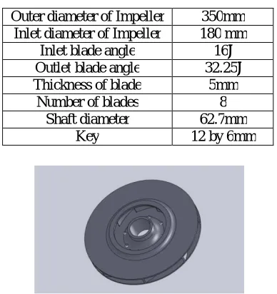
Impeller: The impeller is measured using digital vernier gauge and comparing with CAD drawings the shroud as shown is drawn in the 3D window and revolved and a series of 8 vanes are extruded from the surface.
Table 1: Design Specification of Impeller
Outer diameter of Impeller 350mm Inlet diameter of Impeller 180 mm
Inlet blade angle 16˚
Outlet blade angle 32.25˚
Thickness of blade 5mm
Number of blades 8
Shaft diameter 62.7mm
Key 12 by 6mm
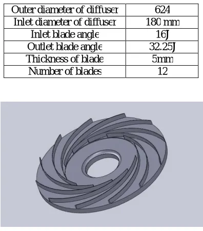
Diffuser: The diffuser is generated by extruding a series of12 vanes are Boss-Extruded from the surface. The diameter of the diffuser is 624mm, blade height is 23.6mm and the central bore is 200mm in diameter.
Table 2: Design Specification of Diffuser
Outer diameter of diffuser 624 Inlet diameter of diffuser 180 mm
Inlet blade angle 16˚
Outlet blade angle 32.25˚
Thickness of blade 5mm
Number of blades 12
Volute/Casing: The volute was designed by revolving the sketch around an axis. The casing of the pump, as per the design charts has a diameter of 635mm and a length of 788mm. The inlet section has a diameter of 450mm and the outlet section has a diameter of 200mm. The outlet pipe extends from the pump for about 3m.
Fig. 3 Solidworks Model of Volute/Casing
Shaft: The shaft of the multistage centrifugal pump was extruded from a circle having diameter of 62.7mm. IV.ANALYSIS
The analysis of the 5 stage centrifugal pump was done using Fluent module in ANSYS workbench. ANSYS is a comprehensive suite that spans the entire range of physics, providing access to virtually any field of engineering simulation that a design process requires.
The incompressible flow through the pump was analysed considering it a pressure based problem as pressure is the phenomena that varies noticeably with the implementation of De-staging. Each stage of the pump impeller was individually analysed for saving time and better accuracy.
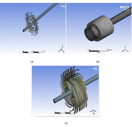
The model generated in the Solidworks work phase is imported in to the fluent window the import was then meshed using a body sizing of 0.01 element size.
Fig. 4 Meshing (a) single impeller stage (b) volute casing with volumetric meshing (c) meshing of all the five stages
The turbulence model was set to k-ε model and the inlet pressure was defined in the inlet face and the outlet was
measured. This outlet pressure obtained was then given to the next stage and the process continued till the final stage until the rated pressure was reached for cross-reference.
Boundary conditions: Centrifugal pump impeller, diffuser and the shaft domain is considered as rotating frame of reference with different rotational speed of 1485 RPM. The working fluid through the pump is water. k-ε turbulence model is used for calculation. Inlet static pressure of-0.05055 kg/cm2for the first stage , 1.23kg/cm2 for the second stage ,2.12 kg/ cm2for the third stage ,6.75 kg/ cm2for the fourth stage,11 kg/ cm2 for the fifth stage and the
(c)
corresponding outlet pressure was calculated with respect to each inlet pressure. Three dimensional incompressible N-S equations are solved with ANN-SYN-S-CFX N-Solver.
V. OBSERVATIONS
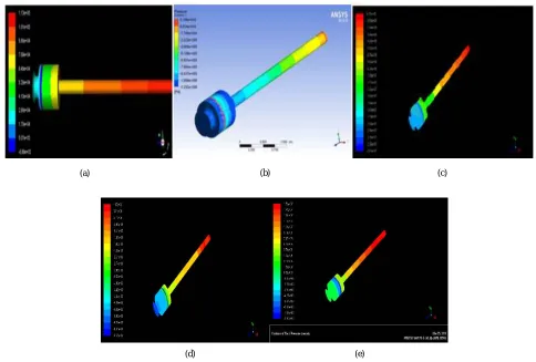
The results obtained from the Ansys Fluent analysis is shown in Fig 5. The various contours obtained show the pressure variation along the length of the pump.
Fig. 5 Observations of pressure contours of different stages (a) First stage single impeller (b) Second stage single impeller (c) Third Stage single impeller (d) Fourth Stage single impeller (e) Fifth Stage single impeller.
Fig 5(a) shows the pressure contour of the first stage impeller. As can be observed from the figure, pressure at outlet is more than pressure at the inlet.
Fig 5(b) gives the pressure contour through the second stage. The inlet condition for this stage is the output of the first stage. Outlet pressure is more than the inlet pressure.
Fig 5(c) is the pressure contour through the third stage. Inlet condition for this stage is taken from that of the output of the first two stages combined. Here also, outlet pressure observed is more than the inlet pressure.
Fig 5(d) shows the pressure contour through the fourth stage impeller. The combined results of the first three stages are given as inlet. We obtain an outlet pressure which is greater than inlet.
Fig 5(e) shows the pressure contour through the fifth stage. The outlet pressure is at maximum in this case.
(a) (b) (c)
The plots obtained from the ANSYS Fluent are depicted in Fig 6.
Fig.6 Result and Plots (a) Static Pressure v/s Position (b) Magnitude of velocity v/s Position (c) Pressure v/s Discharge
Fig 6 shows a simplified plot from the data obtained from the results of the numerical model in Ansys fluent. Fig 6(a) shows the distribution of pressure at inlet and outlet. The pressure at outlet is considerably higher than that of the inlet. Fig 6(b) shows the velocity distribution at inlet and outlet. Fig 6(c) shows the pressure v/s discharge curve. This curve follows the general characteristic behaviour of centrifugal pumps in that the pressure decreases as discharge from the pump increases.
Fig. 7 Velocity Contour of the fluid passing through the pump
(a) (b)
The velocity contour of the 5 stage centrifugal pump shows a high increase in velocity near the impeller stages and a decrease in velocity as it moves toward the discharge which indicates an increase in pressure, as shown in Fig 7.
VI.SUGGESTIONS AND IMPROVEMENTS
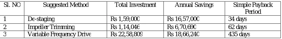
The Simple Payback Period (SPP) of de-staging is compared with impeller trimming and variable frequency drive in the following table. Impeller trimming involves reducing the impeller diameter by machining its outer edges whereas, variable frequency drives employs a variable speed motor to control the speed of the pump shaft.
Table 3: Simple Payback Period
Sl. NO Suggested Method Total Investment Annual Savings Simple Payback
Period
1 De-staging Rs 1,59,000 Rs 16,57,000 34 days
2 Impeller Trimming Rs 1,14,046 Rs 6,70,690 62 days
3 Variable Frequency Drive Rs 22,58,809 Rs 18,66,240 435 days
From the data in Table 3, it is clear that de-staging has the least simple payback period and will be the most economical for the industry.
VII. CONCLUSION
A Computational investigation of pressure variation within the given Condensate Extraction Pump was conducted successfully. The pressure and velocity contours were obtained which define the distribution of pressure and velocity at different regions within the flow area of the pump. The major conclusions drawn are:
1) The simple payback period for De-staging, Impeller trimming and VFD were calculated and found to be 34, 62 and 435 days respectively. Although the VFD is very efficient and smooth to operate, it would be in excess to the needs of the industry. Impeller trimming is irreversible. De-staging, on the other hand, is simple to implement and satisfactorily fulfills the requirements.
2) Solidworks models of impeller, diffuser, shaft and volute casing were constructed on the basis of known specifications and calculations.
3) The CFD model of the pump was created which consists of impeller, diffuser and the volute casing. 4) The pressure levels predicted for different stages have been found to be consistent with data obtained
from de-staging conducted on identical pump.
5) While doing the CFD analysis of de-staging of the CEP, it was found that the pressure drops to about 6.75 kg/cm2, when two impellers are removed. The total head with five impellers were 15.3 kg/cm2. This will considerably reduce the power consumed by the CEP. Hence this condition with de-staging of two impeller stages is the most preferable method of optimizing the flow through the CEP.
REFERENCES
[1] R. Ragoth Singh, M. Natraj, “Design and analysis of pump impeller using SWFS”, World Journal of Modelling and Simulation, Vol. 10, pp. 152-160, 2014. [2] Tejas N. Raval, Dr. R. N. Patel, “Optimization of Auxiliary Power Consumption of Combined Cycle Power Plant”, Sciverse Sciencedirect, Vol. 51, pp. 751-757,
2013.
[3] Harisha S, Dr. Y. J. Suresh, “Rotor Dynamics Analysis of a Multistage Centrifugal Pump”, International Journal of Innovative Research in Advanced Engineering, Vol.3, Issue 9, pp. 16055-16063, 2014.
[4] Timothy J. Cookson, Nicholas G. Lang, Edward J. Thornton, “Adjustable Speed Drives Applied To Large AC Induction Motor And Pump Systems”, Proceedings Of The Twenty Fourth International Pump Users Symposium, pp. 75-80, 2008.
[5] Mr. Jekim J. Damodar, Prof. Dilip S. Patel, “Experimental and CFD Analysis of Centrifugal Pump Impeller – A Case Study”, International Journal Of Engineering Research And Technology, Vol. 2, Issue 6, 2013.
[6] Gurvinder Singh, John W Mitchell, “Energy Savings From Pump Impeller Trimming”, ASRAE, Vol. 40, pp. 60-65, 1998.