Critical Considerations for an Urban Deer
Collaring Program
Erin C. McCance1,2,*, Richard K. Baydack2
1EcoLogic Environmental Inc., Canada
2Department of Environment and Geography, University of Manitoba, Canada
Copyright©2017 by authors, all rights reserved. Authors agree that this article remains permanently open access under the terms of the Creative Commons Attribution License 4.0 International License
Abstract
Capture, handling, and collaring of wildlife in urban environments pose unique challenges compared to similar programs conducted in more remote locations. With urban white-tailed deer (WTD) (Odocoileus virginianus) populations generally increasing across North America, the need to gain a better understanding of urban deer behavior and ecology is essential for effective management. Global Positioning System (GPS) telemetry collars can efficiently track animal movements, and therefore urban deer capture is likely to be increasingly used. This research note offers critical considerations for wildlife managers embarking on an urban deer-collaring program, specifically in northern latitudes, including suggestions for selection of tracking collar, cage trap specifications, and other aspects for capturing and physically immobilizing deer within metropolitan landscapes.Keywords Box Trap, Capture, Collaring, Global
Positioning System, Management, Urban Deer1. Introduction
Increasing human population growth and the tendency toward urban lifestyles have resulted in the extension of city boundaries and the outward development of residential and commercial spaces throughout North America. These human-induced land use changes have modified the continental (and global) landscape, resulting, in some cases, in changes to wildlife species behavior and ecology [1]. In North America, white-tailed deer (Odocoileus virginianus) (WTD) populations have grown over the last several decades, and they have adapted well to life in urban environments [2-4]. WTD exploit the variety of atypical resources available within developed urban spaces. In response to these growing urban deer populations, numerous metropolitan centers in North America are now faced with urban WTD management [1]. Deer populations within urban landscapes
draw controversy given their association with human-wildlife conflict [4, 5]. Overabundant deer populations present human health and safety concerns as well as economic and ecological issues [6, 3, 7], and yet there is a tendency for some urbanites to feel a protectionist orientation toward these wildlife [8]. As a result of the inter-related impacts associated with growing urban WTD populations, research investigating urban deer ecology and behavior is becoming more prevalent. Researchers suspect that urban deer management will become common practice [9]. Understanding deer habitat use and movement patterns within urban spaces is necessary to maximize the success of management [4].
Use of Global Positioning System (GPS) telemetry collars in wildlife research has revolutionized the acquisition of animal-borne locational data, providing valuable information on animal behavior and ecology [10]. GPS technology offers researchers the ability to monitor fine-scale movement with a high degree of accuracy [11]. Urban deer collaring programs, however, pose unique challenges compared to collaring programs designed for more remote locations. This research note offers critical considerations for wildlife managers and researchers embarking on an urban WTD collaring program, specifically in northern latitudes, with respect to tracking collar considerations, cage trap specifications, and other factors. These findings represent some lessons learned during a three-year urban deer- collaring program conducted in the Greater Winnipeg Area (GWA), Manitoba, Canada.
2. Tracking Collar Considerations
2.1. Vhf Technology
Very high frequency (VHF) collars offer an inexpensive, light-weight option for tracking wildlife. Current approximate value of a VHF collar equipped with a drop off mechanism is $400 CDN, in comparison to an average GPS collar (depending on collar capabilities) with drop off has a current approximate value of $2500 CDN [22]. However, various constraints associated with VHF technology limit accuracy and number of locations that can be collected within a given time frame [12]. VHF radio-tracking technology remains a labor-intensive and time-consuming technique [13, 10]. Constraints associated with VHF collars are compounded within an urban environment. Despite their feasibility and attractive weight and size, relying solely on VHF collar technology is challenging in urban environments that are riddled with “noise” due to static and interference associated with utility lines, airline traffic, and hindrance from buildings and homes, along with numerous additional competing radio-frequencies and other variables.
Above-and-beyond these interference issues, radio-tracking of free-ranging ungulates residing within the fabric of residential neighborhoods presents challenges. Researchers attempting to locate collared deer may be confronted with issues of trespassing on private residential properties and/or traversing barrier fencing, making effective acquisition of a target animal’s location difficult. In an effort to obtain a consistent and robust dataset and to ensure that collared animals are not “lost” during a dispersal or migration event, deer must be located often when relying exclusively on VHF technology. Researchers need to ensure that their frequent presence while tracking collared deer does not influence deer movement, specifically within urban spaces comprised of primary and secondary roadways. Researchers need also to ensure that their presence does not “push” target and non-target deer onto and across busy roadways. While VHF technology is an essential complementary component of any tracking collar, relying solely on VHF technology within urban environments is not recommended.
2.2. GPS Collar Specification Considerations
Use of GPS collars on free-ranging ungulates overcomes many of the limitations experienced with conventional VHF collars [14, 12]. GPS collars offer numerous benefits, including more precise locational data, frequent animal relocations, and reductions in temporal biases (daylight, weather) [15]. While GPS collars are equipped with greater technological capacities, they are generally heavier than their VHF counterparts. When selecting a GPS collar, researchers often consider the balance between battery power (collar life longevity based on fix schedule programming) and collar weight. In general, weight reduction indirectly affects the longevity of the GPS collar [16]. Within an urban environment, GPS collar weight and overall collar volume are important. Urban residents have a wide range of
perspectives with respect to deer residing within their neighborhoods [17], and may or may not agree residents may view urban deer as they would their domestic pets and as such, feel protective of their well-being [18, 8].
Based on best practices of animal ethics [19], when deer are exposed to the stress of capture and handling, researchers aim to ensure that the maximum amount of data possible is acquired from the undertaking. As a general “rule of thumb”, a tracking collar can weigh up to 3-5% of an animal’s body weight [20, 21]. Researchers may be tempted to select a heavier collar in order to acquire data on the same research animal over multiple years. As an example, a 950 gram GPS tracking collar falls well within this weight category for WTD, and on average, if programmed to acquire a latitude and longitude locational fix every two hours, would last approximately two years [22]. Based on the experiences of our urban deer collaring program, however, we would be cautious in using a GPS collar weighing 950 grams for future urban deer research. A ‘heavy’ GPS collar, regardless of fit upon collaring, can be associated with hair loss, chaffing, and rubbing of the skin around the animal’s neck, not to mention the collar’s potential appearance to some urban residents as cumbersome and overly invasive [17]. Despite a desire to learn as much as possible from a collaring program and a subsequent tendency to choose a collar with a larger battery and therefore, increased collar longevity, researchers in an urban environment should be cautious with respect to the weight of the collar they select.
A further consideration as to the overall collar weight is deer behavior, which in and of itself exacerbates collar hair wear. Deer foraging behavior results in the repeated motion of deer dropping their heads down to the ground to feed and then lifting their heads back up again. This continual up-and-down motion results in slight collar movement along the neck. Collaring mature does and avoiding the collaring of yearlings will assist researchers in acquiring a better collar fit at the time deer are collared. However, in our experiences, even a doe with a collar sized effectively and snug at the time of capture is likely to experience some degree of collar movement along the neckline throughout the year, as her body condition fluctuates and her coat changes seasonally - with spring, in northern latitude of the GWA (approximately 49°53'58'N, 97°08'21'W), showing the most pronounced collar movement and associated effects (Figure 1). The repeated motion of the GPS collar, even slightly along the neckline, may result in damage to winter pelage, more substantial hair-wear, and in some cases, chaffing of the skin, a situation exacerbated by a heavy collar. Urbanites observing collared deer displaying these conditions may become alarmed, resulting in increased public concerns and increased pressure on both the research objectives and the researcher.
shape of the animal’s neck, with minimal collar volume, can reduce unnecessary attention being drawn to urban collared animals.
[image:3.595.58.297.124.314.2]Photo taken by: E.C.McCance
Figure 1. Large GPS collar volume and doe hair wear in spring
Photo taken by: E.C.McCance
Figure 2. Rat Trap Trigger
Photo taken by: E.C.McCance
Figure 3. Cage Trap
2.3. GPS Collar Drop-Offs
Within metropolitan spaces, re-trapping a collared target animal can be a difficult undertaking. Inside city spaces, aerial capture is often restricted; the use of cannon or rocket launched nets may draw undesirable attention; chemical immobilization of free-ranging ungulates in a matrix of busy roadways presents safety hazards; and the selective recapture of an already captured deer by drop-net and box trap can be difficult and time-consuming. Using an automatic drop-off mechanism associated with the tracking collar eliminates the need for the researcher to re-capture target animals, thereby reducing stress on the animals (NPWRC: http://www.npwrc.usgs.gov/). While timed-drop-off units do not require the researcher to recapture the collared animal, they do not offer the flexibility of remotely releasing the collar upon command. Given the unique dynamics inherent within an urban deer-collaring program, researchers should consider the use of a collar and drop-off mechanism that offers two-way communication and support the collar release upon command.
3. Cage Trap Selection Specifications
Considerable time, energy, and expense are involved in capturing urban WTD [23, 24]. The most critical aspects of handling WTD are ensuring safety, efficiency, and humane capture [23]. Cage traps have long been used as a safe and humane method of capture. Clover box traps have been reported as an effective deer capture method associated with lower levels of induced stress in WTD in comparison with other available capture methods [25]. VerCauteren [23], using Clover box traps, captured over 1,000 WTD with less than 4% of captured deer suffering injury. Clover box traps offer a lighter weight and portable option (multiple traps can fit into the back of a truck bed) than some of the traditional box traps, such as the Stevenson box trap [23]. Deer are likely to enter into the Clover box trap with less hesitance given deer can see through the mesh sides. Mesh sides also provide the advantage of pliable material that yields to deer and handler movement within the trap, resulting in less injury. The disadvantage to the Clover box trap is that restrained deer are vulnerable to potential predation and to surrounding disturbances [23].The single-gate netted cage trap, which bears the Clover trap name, was first reported by Melvin Clover in 1954, with a revision to trap specifications published in 1956 [26, 27]. In 1975, modifications for trap collapse and suggested improved efficiencies to the overall trap design were reported [28]. More recent modifications to trap specifications were published by VerCauteren [23].
[image:3.595.58.296.337.661.2]weigh well over 90 kg/200 lb), in combination with physical vs. chemical immobilization of deer, require a heavier trap. Wildlife managers and researchers may find the heavier trap model to be useful given that urban white-tails will likely continue to improve their body condition in response to the annual supply of atypical food sources available in metropolitan spaces. Therefore, use of a heavier gauge cage trap for ground capture of WTD (both in northern and mid-continental latitudes) may prove beneficial. Detailed instructions for the modified box trap assembly are available as on-line Supplementary Materials.
4. Trap Placement, Timing, Baiting and
Handling
4.1. Urban Cage Trap Placement
Within an urban environment, finding a suitable and safe trapping location can be a challenging. Capture and handling within city spaces with high human population density and a maze of road networks presents safety concerns for both people and deer. Trap locations should be selected as far away as possible from roadways and walking trails that they can be effectively concealed and that disturbance around the trap can be minimized. Trap placement must consider safe deer escape routes, thus reducing the risk of a post-captured, stressed deer running out onto roadways and being involved in a deer-vehicle collision (DVC). To maximize success, traps should be placed in high deer activity areas, including trails between bedding and feeding areas [23].
Property ownership within urban spaces can present complications to selection of trapping sites. Finding public property that represents high levels of deer activity and that meets suitable and safe trapping site requirements can be difficult. Private residential properties offer possible suitable trapping locations; however, finding properties that are large enough to conceal trapping activities, and to provide suitable escape routes for deer without barrier fencing and other obstructions is challenging. In addition, while one property owner may be on board and supportive of research and allow capture activities on his or her property, neighbors may not be, possibly resulting in conflict.
4.2. Urban Cage Trap Set-Up
Cage traps used for physical immobilization of deer must be anchored to remain upright during capture and handling. Ideally, cage traps should be placed in a small open area (approx. 6 feet x 6 feet) with four solid trees or other objects located near each corner of the trap. This site where the trap is placed should be cleared, paying particular attention to any braches poking up that could result in injury to the deer and/or handlers. Traps should be placed in such a way that the trap door faces the direction that the handlers will approach [23], driving the deer to the back of the trap, and allowing enough room for handlers to enter the front of the trap to physically immobilize the deer. The four top corners
of the trap should be firmly anchored (ratchet straps are effective), to the base of four solid trees (if available), or anchored to stakes driven into the ground near trap corners. For the safety of both handlers and captured deer, ensuring that trap corners are firmly anchored and the trap is solid against the ground with little or no side-to-side movement, is important when physically immobilizing deer. Handlers should be aware of the direction of the trap door to ensure that post-captured deer are released in a clear and safe direction, void of heavy human-activity areas, fencing, buildings, or busy roadways. A clearing of at least 15 m should be present in front of the trap [23] to reduce likelihood of deer injury upon release.
Traps can be repeatedly set in the same location until the success of capture begins to decline. In our experiences, after 2-3 active trapping nights, trap sites became stale. Similar to the findings of VerCauteren [23], however, by moving the trap slightly, trapping success can be increased.
4.3. Urban Capture Timing
Trapping activities are most successful in northern latitudes during winter months, between December and March, after the rut, yet before does enter their third trimester of pregnancy [29]. During this time in our northern latitude, deer are food- stressed and most easily captured. Capturing during the cold (on average, during this research, trapping night temperatures fell between -15 to -20 degrees Celsius, but no colder than -25 degrees Celsius with the wind chill, the temperature at which capture activities were halted) and dark months, is beneficial in an urban environment given it reduces the amount of outdoor human activity in and around trapping locations.
Integral to city spaces are relatively high levels of human activity, lights, loud noises, traffic, and dogs. While it is likely that urban deer are habituated to these conditions, trapped deer exposed to these disturbances are likely subjected to increased stress. In an effort to reduce unnecessary stress to captured deer, we opted to limit capture times during daylight and restrict our capture efforts to times between dusk and dawn. Further, despite research suggesting that traps within a forested landscape need to be checked only twice within 24 hours [23], we tightened the frequency within which traps were checked, in order to reduce the time frame captured animals were confined and exposed to higher risks of disturbance present within urban spaces. In combination with concerns over reducing stress experienced by captured deer, were considerations for perceptions of urbanites potentially exposed by happenstance to captured animals. Therefore, each evening trap was set at dusk and checked between 8:30-9:00 pm, again at 11:30-12:00 pm, and finally between 5:30-6:30 am, after which, the traps were secured open and left unset for the remainder of the day.
4.4. Urban Cage Trap Bait
component of any trapping program; however, researchers conducting deer movement studies should be mindful that their pre-baiting is not conducted over a lengthy time frame, possibly influencing deer movement, and resulting in potential home range shifts. An unfortunate downfall of using capture methods that require bait is that attracted animals must be lured to bait, thereby depending on the objectives of the research, biasing the study animals to an artificial food source. Our experiences suggest that pre-baiting in areas with high-deer activity levels is not required more than 24-48 hours prior to capture. During our capture program, sweet feed (Landmark Feeds), an intended horse feed primarily made up of barley, oats, and corn covered with molasses) was the most effective bait used (higher activity rates observed with sweet feed in comparison to when oats and barley used). We did not have any success with the use of salt/salt blocks to attract deer to traps, even in early spring, possibly due to the increased availability of artificial supplies of salt already found in generous quantities within northern urban environments where salt is used to melt ice to improve driving conditions on roadways.
During the 24-48 hours prior to capture, traps should be placed on site and tied open, allowing deer to become acclimatized to their presence. Traps should be baited and deer should be allowed to move freely in and out of the trap to access bait. Small bait piles should be placed outside of a trap, with a small trail of bait leading into it. Researchers should be careful not to supply large amounts of bait outside of the trap reducing the need for deer to access bait within. A larger bait pile should be placed at the back of the trap, behind the trip string location, but far enough away from trap sides that deer cannot access the food from outside. Once deer are actively on the bait and freely moving in and out of the unset trap, capture activities should commence. If deer are not using bait frequently after several days, researchers may want to consider moving the trap slightly or selecting a new trap location.
4.5. Deer Handling: Physical Immobilization
In situations where chemical immobilization may not be feasible or warranted, manually restraining deer can be a very quick and effective method for affixing ear-tags and research collars [23]. Manual restraint should involve 2-3 handlers. As handlers approach an active trap, the activity level of the confined deer increased. Handlers should move as quickly as possible toward the trap and enter through the trap front door. Handlers should avoid hesitation and enter the trap with confidence in order to reduce the opportunity for un-controlled activity within the trap. Upon entering the trap, the first handler should pin the deer to the back of the trap, bear-hugging the animal, using the handler’s body weight over top of the animal’s back, tucking the deer’s front legs up underneath its chest, and lowering the deer toward the ground. During this time, the second handler should enter
the trap and assist in lowering the deer safely to the ground while carefully controlling the position of the deer’s head and neck. Handlers should be cautious of the deer’s hind legs and position themselves behind the deer’s body opposite of the hind legs, being prepared that the deer may use power in their legs to push upwards. The time between the deer’s awareness of the handlers presence in the vicinity of the trap, to the time when the deer is safely immobilized within the trap, represents the most precarious time frame of the capture, with the highest risk potential for injury. Handlers should work efficiently to reduce this time frame as much as possible and quickly establish a control hold over the deer for the safety of the deer and crew.
Once safely restrained, the deer is blindfolded and hobbled. The front and back leg on each side of the deer are hobbled to restrict deer movement and their ability to kick handlers. A winter neck warmer or a portion of a sweatshirt sleeve makes for efficient blindfolds. During the course of our research, the capture team handled both non-antlered and antlered bucks in the Modified Clover Box Traps. In our experiences, antlered males were easier to handle than non-antlered males. The antlers provided handlers with an improved efficiency to establish control of the buck’s movement and stabilize its head and neck. In a majority of the cases where antlered bucks were restrained within the Modified Clover Box Trap, there were no issues with the antlers becoming tangled in the trap mesh; however, in the case where the antlers did become entangled (n = 1), capture crews removed (time <5 minutes) the antlers from the netting using antler cutters.
Occasionally, released animals immediately drop to the ground upon release, attempting to remove the GPS collar with their back hooves. In these cases, where possible, handlers would assist the collared deer back onto their feet and safely re-direct them.
5. Management Implications
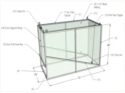
3D Image by: W.Carson McCance
Figure 4. 3D Image of Modified Clover Box Trap
[image:6.595.63.547.438.721.2]Table 1 represents a list of materials required for Modified Clover Box Trap construction and set-up.
Table 1. List of Materials for Modified Clover Box Trap Construction Item
Number Item Length (inches) Length (mm) of pieces Number 1 Length pieces (1 inch square tubing) 72 1829 4 2 Width pieces (1 inch square tubing) 34 864 4 3 Upright pieces (1 inch square tubing) 48 1219 4 4 Drop-door guide upright (1 inch square tubing) 48 1219 2
5 Door pull-down bar (3/4 inch rod) 27 686 1
6 Door pull-down end rings 2.5 64 2
7 3/8 bolts and locking nuts 3 76 24
8 1.5-2" (38-51mm) mesh netting 48 x 34 (ends) 48 x 34 (ends) 2 9 1.5-2" (38-51mm)mesh netting 134 x 74 (sides & top) 134 x 74 (sides & top) 1 11 threaded I-bolts (tie-down leads) 1.5" eye with 3/8 x 1.5" bolt 38mm eye with 10 x 38mm bolt 4 12 threaded I-bolts (trip string leads) 0.75 eye with 1/4 x 1.5" bolt 19mm eye with 6 x 38mm bolt 6
13 Rat trap (trigger) 3 1/4 x 7 83 x 178 1
14 String 96 2438 2
15 Cotter pin 3 76 1
16 Paper clip large large 1
17 Corner angle supports (1 inch (25mm)square tubing, lighter tubing can be used) 24 24 2
18 Trigger string supports (1 inch (25mm) square tubing, lighter tubing can be used) 50 1270 2 19 Square Wire Locking Pin 3 x 3/8's 3 x 10mm 4
20 Outdoor Cable ties 8 8 4+
Acknowledgements
We thank the Parks Canada biologists and wildlife technicians T. Sallows, D. Bergeson, R. Robinson, and R. Grzela at Riding Mountain National Park for the contribution of the trap design, animal handling, and overall research objectives.
Supplementary Materials
Additional supporting information may be found in the online version of this article at the publisher’s web-site. “Step-by-step” instructions for trap assembly, presented in a “how-to” manual style of the assembly for the modified version of the Clover Box Trap are presented.
Step-by-Step Assembly Instructions
Materials for trap assembly are number and represented in Table 1 and Figure 4.Step 1: Ensure all of the frame pieces (item numbers 1-5) are cut to length.
Step 2: Using a 3/8” (10 mm) bit (and a drill press, if available), drill holes 3/4” (19 mm) from both ends of the 48” (122 cm) pieces (item number 3).
Step 3: Drill additional holes 1 1/2” (38 mm) from both ends of the 48” (122 cm) tubing, perpendicular to the first holes (item number 3).
Step 4: Drill one hole 20” (508 mm) 2 of the uprights (item number 3), in same direction as the end holes drill in Step 2 – these drill holes will be placed down from the top of the trap when assembled (see Figure 4). These holes will be used for the support bars to be placed in the opposite corners of trap.
Step 5: On the two drop-door uprights, drill holes 1 ½” (38 mm) from both ends of the 48” (122 cm) frame pieces (item number 4).
Step 6: Weld the 2 ½” (64 mm) rings to the ends of the pull-down bar (item number 5).
Step 7: On the tubing frame pieces that form the length of the frame (item number 1), drill holes 5” (127 mm) from both ends of the top 66” (168 cm) pieces, to be used for the tie down strap 1 1/2” (13 mm) I-bolts. The ratchet straps run through these I-bolts and are used to anchor the trap firmly to the ground.
Step 8: Along the top left 66” (168 cm) length tubing (item number 1) if you were looking at the front of the trap, drill two holes at 45” (114 cm) and 49” (125 cm) from the front, which will be used for the rat trap attachment.
Step 9: Using a 1/4” (6 mm) bit, drill two holes at 12” (305 mm) and 33” (838 mm) from the front of the top left 66” (168 cm) piece (item number 1) for the trigger assembly.
Step 10: Using the 3/8” (10 mm) bit, drill holes 3/4” (19 mm) from both ends of all top length pieces (item number 1) and 24” (610 mm) from the back end of both bottom 66” (168 cm) pieces (item number 1) perpendicular to all the
other holes (note: 4 additional holes will need to be drilled later in the construction process, into the top length pieces, toward the back of the trap.) These holes are drilled later in the construction process to facilitate proper placement of the holes in order to adequately match the drill hole to the exact position on the support bars.
Step 11: On the width bars of the trap frame, drill holes 3/4” (19 mm) from the ends of 34” (864 mm) pieces (item number 2) and drill holes 2 ½” (64 mm) from ends of the 34” (864 mm) front pieces.
Step 12: drill two ¼” (6 mm) holes 2” (51 mm) apart in the middle of the top front 34” (864 mm) bar (item number 2), as these holes are used later for the trigger assembly.
Step 13: On the frame tubing that will become the angled side support bars, drill holes 3/4” (19 mm) from the ends of the 24” (610 mm) (item number 17) and 50” (127 cm) pieces (item number 18).
Step 14: On the 50” (127 cm) side support bar pieces (item number 18), drill four, ¼” (6 mm) holes, at 3” (76 mm) spacing starting at 16” (406 mm) from bottom, perpendicular to the end holes. These drilled holes are used for adjusting the height of the trip string as required once the trap is set in the field.
Step 15: Assembly of the trap requires a minimum of two people. Initially, lay out the tubing frame lengths, widths, and uprights into a configuration that allows for easy attachment. Place the two uprights, with support bar holes, in opposite corners.
Step 16: Place the 2 length pieces of the frame with the I-bolt holes in the top position and the 2 length pieces of the frame with the support bar holes in the bottom position, ensuring the rat trap support holes are positioned to the back of the trap.
Step 17: Run the 3/8” (10 mm) bolts from the inside of the trap out and hands tighten the bolts to form the basic frame of the trap.
Step 18: Attach the length pieces of the frame to the outside of the uprights into the end holes.
Step 19: Attach all width pieces of the frame to the outside of the uprights, except the back bottom width bar, which goes inside.
Step 20: Prop the trap up, in this loose assemblage, to weave the meshing onto the bars, starting with the side and top pieces.
Step 21: Weave the mesh onto the bottom bar first and work the mesh upwards, up and over the top portion of the frame and down toward the other bottom bar. Weaving the mesh onto the top bars is important to ensure animals do not get caught up between mesh and bars. The back end and side meshing will need to be weaved to the uprights and width bars simultaneously.
(1975) modified Clover design, the trap corners are constructed to pivot, allowing handlers to collapse the trap for transport and, if desired, for handling.
Step 23: Attach the four support bars to the already drilled holes on the uprights (corner supports 24” [610 mm]) and bottom length frame bars (50” [127 cm] supports). Square off the trap and raise the support bars to the top length and mark the spot for drilling the holes for attachment.
Step 24: The placement of the support bar drill holes should be approximately 14” (356 mm) and 20” (508 mm) from the back of trap on one side and approximately 15” (381 mm) from the back and 14” (356 mm) from the front on the rat trap side.
Step 25: Use the 3” (76 mm) square locking pins to hold the supports to the top bar with the detachment to the outside so the bar can by knocked off easily by the animal movement in the trap without injury. Use cable ties to attach the locking pins to the trap so they do not get lost during transport and capture.
Step 26: With respect to the door assembly, weave the door mesh to the front top width. From the top down, weave the door uprights loosely through the door mesh into every second square and weave the drop-door weight bar through the bottom of the door mesh. Depending on the cut of the mesh, a square or two may need to be cut away to fit the mesh over the steel rings.
Step 27: Attach the uprights to the upper and lower widths and test the mesh door to make sure it moves and drops down easily. Ensuring the door will easily fall and drop with the appropriate weight is important so captured deer cannot escape through a front trap door that does not fall properly. Tighten all bolts on the door assembly snuggly.
The present research used both an s-hook (VerCauteren et al. 1999) as well as a rat trap trigger system. Both trigger systems were used with success.
Step 28: The rat trap trigger assembly requires the attachment of the rat trap to the appropriate top left length frame bar using the predrilled holes, and securing the trap to the frame using with shorter 2 ¼” (57 mm) bolts (Figure 2).
Step 29: Drill 2 holes into the rat trap about 1 1/2” (38 mm) from the side, in order to align the trap with the holes on the bar.
Step 30: Drill a ¼” (6 mm) hole directly under the trap dog-down lever in order to run the trip string through it.
Step 31: Attach the trip string I-bolts to the support bars and also attach the trigger string guide I-bolts to the top of the frame length bar and front width bar above the door.
Step 32: Attach the four I-bolts to the four top corners of the trap, which will be used for the tie down straps. Cut the trip string and trigger string to appropriate length for the trap as required.
Step 33: The trip string (item number 14) should have 1” (25 mm) loops at both ends and be approximately 70” (178 cm) in total length. Run one end of the string with a loop up through rat trap hole under the dog-down lever and attach the string loop to the dog-down lever. Run the string down to the
support bar I-bolt (on the left side of the trap) and then through trap, creating the portion of the trip string the animal will knock when in the trap. Proceed to run the string across the inside of the trap to the other support I-bolt on the other side of the trap opposite to the rat trap trigger and use a paperclip to attach the trip string to the support bar I-bolt. The present research used the paper clip successfully, given that the paper clip is flexible enough to be pulled down by the animal after the trigger is sprung.
Step 34: The trigger string should have 1” (25 mm) loops at both ends and be approximately 60” (152 cm) in total length. Attach the trigger string loop to the rat trap striker and run the trigger string through the two I-bolts up to the front corner of the trap and along the front of the trap to the top middle of the front door width I-bolts.
Step 35: Attach a 3” (76 mm) cotter pin (item number 15) to the end loop. It is important to allow for slack in this string between the striker spring bar and the cotter pin to allow the rat trap to gain enough momentum to pull the cotter pin free from the weight of the drop-door. Test the trigger string and trip string repeatedly.
Step 36: The door release string should have 1” (25 mm) loops at both end and be approximately 20” (508 mm) in total length. Attach to the top width door frame and run from inside of the door under the mesh and Drop-door weight bar. The other loop of the door release string will be used between the two I-blots on the door width. Use the cotter pin through the door release string loop to hold the door up when the rat trap is set for action.
REFERENCES
[1] Adams, C. E., K. J. Lindsey. Urban Wildlife Management, 2nd
Edition. CRC Press, Boca Raton, London, and New York; 2010.
[2] Kilpatrick, H. J., S. M. Spohr. Spatial and Temporal Use of a Suburban Landscape by Female White-Tailed Deer. Wildlife Society Bulletin 2000; 28: 1023-1029.
[3] Etter, D. R., K. M. Hollis, T. R. Van Deelen, D. R. Ludwig, J. E. Chelsvig, C. L. Anchor, R. E. Warner. Survival and Movements of White-Tailed Deer in Suburban Chicago, Illinois. Journal of Wildlife Management 2002; 66: 500-510. [4] Bender, L. C., D. P. Anderson, J. C. Lewis. Annual and
Seasonal Habitat use of Columbian Black-Tailed Deer in Urban Vancouver, Washington. Urban Ecosystems 2004; 7: 41-53.
[5] Decker, D. J., T. L. Brown, W. F. Siemer. Human Dimensions of Wildlife Management in North America. Bethesda, Maryland: The Wildlife Society; 2001.
[6] Decker, D. J., T. A. Gavin. Public Attitudes toward a Suburban Deer Herd. Wildlife Society Bulletin 1987; 15: 173-180.
Woodson. Determinants of Public Perceptions of Suburban Deer Density. Human Dimensions of Wildlife 2013; 18: 82-96.
[8] Manfredo, M. Who Cares About Wildlife? Social Science Concepts for Exploring Human-Wildlife Relationships and Conservation Issues. Springer, New York; 2008.
[9] Grund, M. D., J. B. Mcaninch, E. P. Wiggers. Seasonal Movements and Habitat Use of Female White-tailed Deer Associated with an Urban Park. Journal of Wildlife Management 2002; 66: 123-130.
[10] Blackie, H. M. Comparative Performance of Three Brands of Lightweight Global Positioning System Collars. Journal of Wildlife Management 2010; 74: 1911-1916.
[11] Van Moorter, B., D. R. Visscher, Christopher L. Jerde, Jacqueline L. Frair, Evelyn H. Merrill. Identifying Movement States from Location Data Using Cluster Analysis. Journal of Wildlife Management 2010; 74: 588-594.
[12] Kochanny, C. O., G. D. Delgiudice, J. Fieberg. Comparing Global Positioning System and Very High Frequency Telemetry Home Ranges of White-Tailed Deer. Journal of Wildlife Management 2009; 73: 779-787.
[13] Samuel, M.D., and M. R. Fuller. Wildlife Radio-Telemetry. In Research and Management Techniques for Wildlife and Habitats. Fifth Edition. The Wildlife Society, Bethesda, Maryland, USA 1996: 370-418.
[14] Rodger, A. R., S. Remple, and K. F. Abraham. A GPS-Based Telemetry System. Wildlife Society Bulletin 1996; 24: 559-566.
[15] Johnson, C. J., D. C. Heard, and K. L. Parker. Expectations and Realities of GPS Animal Location Collars: Results of Three Years in the Field. Wildlife Biology 2002; 8: 153-159. [16] Tomkiewicz, S. GPS Applications for Wildlife: A Review.
Telonics Quarterly 1996; 9: 1–12.
[17] McCance, E. Urban Resident Opinions Concerning Urban Deer Management in the Greater Winnipeg Area, Manitoba, Canada. M. Env. Thesis, University of Manitoba, 2009. [18] Manfredo, M. J., T. L. Teel, A. D. Bright. Why Are Public
Values Toward Wildlife Changing? Human Dimensions of Wildlife 2003; 8: 287-306.
[19] Canadian Council for Animal Care. 2013. Webpage: http://www.ccac.ca/en_/standards/guidelines. Accessed on April 25, 2013.
[20] Cochran, W. M. Wildlife Telemetry. S.D. Schemnitz editor. Wildlife Management Techniques Manual. Fourth edition. The Wildlife Society, Washington, DC, USA; 1980. pp. 507-520.
[1] Sirtrack: Wildlife Tracking Solutions webpages. 2013. Sirtrack homepage. <http://www.sirtrack.com/index.php/terr estrialmain/vhf/collar> Accessed on April 25, 2013.
[21] Lotek Wireless webpages. 2012. Lotek homepage. <http://www.lotek.com>. Accessed November 11, 2012. [22] VerCauteren, Kurt, C., Jeff Beringer, S. E. Hygnstrom. Use of
Netted Cage Traps for Capturing White-Tailed Deer. University of Nebraska, Wildlife Damage Management, Internet Center for USDA National Wildlife Research Center, University of Nebraska; 1999.
[23] DelGuidice, G., B. A. Sampson, D. W. Kuehn, M. Carstensen Powell, J. Fieberg. Understanding Margins of Safe Capture, Chemical Immobilization, and Handling of Free-Ranging White-Tailed Deer. Wildlife Society Bulletin 2005; 33: 677-687.
[24] DeNicola, A. J., R. K. Swihart. Capture-Induced Stress in White-Tailed Deer. Wildlife Society Bulletin 1997; 25: 500-503.
[25] Clover, M.R. A Portable Deer Trap and Catch-Net. California Fish and Game 1954; 40: 367-373.
[26] Clover, M. R. Single-Gate Deer Trap. California Fish and Game 1956; 42: 199-201.
[27] McCullough, D. R. Modification of the Clover Deer Trap. California Fish and Game 1975; 61: 242-244.
[28] VerCauteren, K., S. Hygnstrom, J. Beringer. Use of Netted Cage Traps in Population Management and Research of Urban White-Tailed Deer. University of Nebraska, Wildlife Damage Management, Internet Center for USDA National Wildlife Research Center; 1997.