Design and Implementation of Fuzzy Logic Controller for an Intelligent Gantry
Crane System: Robustness Evaluatio
n
Wahyudi
1and Jamaludin Jalani
21
Department of Mechatronics Engineering, International Islamic University Malaysia,
Jalan Gombak, 53100, Kuala Lumpur, MALAYSIA
E-mail: [email protected]
2
Department of Mechatronics and Robotics, Kolej Universiti Teknologi Tun Hussein Onn,
Batu Pahat, Johor, MALAYSIA
[email protected]
Abstract
The use of gantry crane systems for transporting payload is very common in industrial application. However, moving the payload using the crane is not an easy task especially when strict specifications on the swing angle and on the transfer time need to be satisfied. To overcome this problem, an intelligent gantry crane system had been introduced. Fuzzy logic controllers were adopted, designed and implemented for controlling payload position as well as the swing angle of the gantry crane. In this paper, robustness of the proposed intelligent gantry crane system is evaluated and compared with an automatic gantry crane controlled by the classical PID controllers. The result shows that the intelligent gantry crane system is more robust to parameter variation than the automatic gantry crane system.
1. Introduction
Gantry cranes are widely used in industry for transporting heavy loads and hazardous materials in shipyards, factories, nuclear installations, and high building construction. The crane should move the load as fast as possible without causing any excessive movement at the final position. However, most of the common gantry crane results in a swing motion when payload is suddenly stopped after a fast motion [1]. The swing motion can be reduced but will be time consuming (i.e. reduce the facility availability as well as productivity). Moreover, the gantry crane needs a skilful operator to control manually based on his or her experiences to stop the swing immediately at the right position. Furthermore to unload, the operator has to wait the load stop from swinging. The failure of controlling crane also might cause accident and may harm people and surrounding.
Various attempts in controlling gantry cranes system based on open loop system were proposed. For example, open loop time optimal strategies were applied to the crane by many researchers [2,3]. They came out with poor results because open loop strategy is sensitive to the system parameters (e.g. rope length) and could not compensate for wind disturbances. Another importance of open loop strategy is the input shaping introduced by Karnopp [4], Teo [5] and Singhose [6]. However the input shaping method is still an open-loop approach.
On the contrary, feedback control which is well known to be less sensitive to disturbances and parameter
variations [7] is also adopted for controlling the gantry crane system. Recent work on gantry crane control system was presented by Omar [1]. The author had proposed PD controllers for both position and anti-swing controls. However, it is well known that controlling the position by using PD controller will cause higher steady state error and low sensitivity to disturbance. The PID controller was also proposed for controlling the gantry crane system [8]. However the performance of the controller degrades when the actuator saturates [8]. In addition, the classical PID controller has to be designed based on the model and parameters of the plant. It is well known that modeling and parameters identification are time-consuming processes.
To overcome the above-mentioned problem, a fuzzy-based intelligent gantry crane system has been proposed [9]. The proposed fuzzy logic controllers consist of position as well as anti-swing controllers. The f uzzy logic control l e r s w e r e designed based on information of the skillful operators and without the need of crane model and its parameters. The performance of the proposed intelligent gantry crane system had been evaluated experimentally on a lab-scale gantry crane. It was shown that the proposed system has a good positioning performance as well as a good capability to suppress the swing angle in comparison with the cran e controlled by the PID controllers [9]. However, the robustness of the proposed system has not been clarified yet. Robustness is also an important performance in the practical applications of the crane system since most of the crane systems are characterized by parameter variations. In this paper, robustness of the proposed intelligent gantry crane system is evaluated. The evaluation result showed that the intelligent gantry crane system not only has produced good performances compared with the automatic crane system controlled by classical PID controllers but also the proposed system is more robust to parameter variation than the automatic crane system controlled by classical PID controllers.
2. System description
2.1 Lab-scale gantry crane
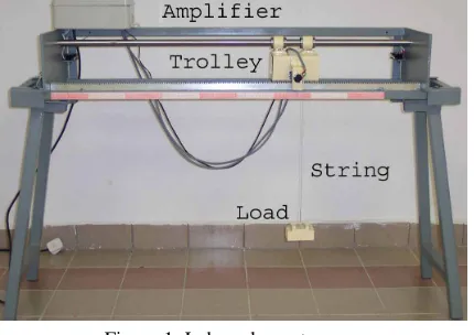
software/hardware. A DC motor and its driver are used to move trolley in which the payload is connected. The rack and pinion mechanism is adopted to allow the trolley guided by a shaft moving along working space. Two potentiometers are used to measure trolley position and payload swing angle. Then potentiometer outputs are used as feedback to the controllers. The lab-scale gantry crane used only considers the planar movement of trolley with fixed load and length of the string. The hoisting mechanism used for lifting/unloading is also not considered.
Figure 1: Lab-scale gantry crane
2.2 Dynamic model of gantry crane
The mathematical model of the lab-scale gantry crane was developed and its parameters are identified [10]. The developed gantry crane model is only used to design classical PID controller, which is used as a comparator, and to make simulation. The developed model of the crane is [10]
) 1 9804 . 0 0788 . 0 (
10 . 5 )
( ) (
2+ +
=
s s
s s U
s
X (1)
981 40 ) (
) (
2 2
+ − = Θ
s s s
X
s (2)
where U(s), X(s) and Θ(s) are input voltage, trolley displacement and load swing angle respectively.
3. Controller design
3.1 Proposed control structure
The structure of the proposed controller for the gantry crane system is shown in Figure 2. The proposed controller consists of fuzzy logic controllers for both position and anti-swing control respectively. The objective of the proposed fuzzy logic controllers is to control the payload position X(s) so that it moves to the desired position Xref(s) as fast as possible without excessive swing angle of the payload Θ(s). Here, the design of fuzzy logic control is based on a heuristic approach. For example the expert knowledge of skillful operator during the manipulation of gantry crane system is adopted in fuzzy logic controller design. It shows that fuzzy logic controller is a controller that may realize the skill of human operators and the design rules describe the subjective fuzziness of operators’ experiences instead of the use of mathematical model of the plant as modern control theory approaches.
Fuzzy logic controller is one of the recent developing methods in control that earned its popularities. The idea behind the fuzzy logic controller is to write the rules that operating the controller in heuristic manner, mainly in If A Then B format. In general, as shown in Figure 3, fuzzy logic controller is constructed by the following elements [11]:
a. A rule base (a set of If-Then rules), which contains a fuzzy logic quantification of the expert’s linguistic description of how to achieve good control.
b. An inference mechanism (also called an “inference engine” or “fuzzy inference” module), which emulates the expert’s decision making in interpreting and applying knowledge about how best to control the plant.
c. A fuzzification interface, which converts controller input into information that the inference mechanism can easily being used to activate and apply rules. d. A defuzzification interface, which converts the
conclusions of the inference mechanism into actual inputs for the process.
Gantry Crane Fuzzy Logic
Controller
Fuzzy Logic Controller Xref(s)+
- +
- Θ(s)
X(s) Position Control
Anti-swing Control
Figure 2 Proposed fuzzy-based intelligent gantry crane system
Plant Reference
r(t)
D
ef
uz
ifi
ca
tio
n
Fu
zi
fic
at
io
n
Inference mechanism
Rule base
Input
u(t) Outputy(t)
Figure 3: Fuzzy controller structure
Another important part of fuzzy logic controller is linguistic variable. Linguistic variable plays the key role in many of its applications, especially in the realization of fuzzy expert systems and fuzzy logic control. Basically, a linguistic variable is a variable representing words or sentences in natural language. For example, in the fuzzy controller design for gantry crane the words Negative Big (NB) for error may correspond to the Positive Big (PB), Negative Small (NS) or Positive Small (PS) of the voltage whereby the actual Negative Big of error represents specific range value. In brief, the linguistic variable is one of the important parts for tuning process of fuzzy logic controller to achieve the desired control process.
3.2 Design of Fuzzy Logic Controller
defuzzification method. In the position control, error and error rate of position are taken into consideration as inputs. On the other hand, swing angle and swing angle rate are used as inputs for anti-swing control. Meanwhile, the voltage is taken as an output. Since there is no specific form to be used when designing fuzzy logic control [10], thus, the basic triangle and trapezoidal forms are chosen for input and output membership functions. In most cases, the performance of fuzzy control is minimally influenced by the shapes of memberships, but mainly by the characteristics of control rules [11].
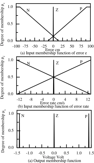
[image:3.612.340.527.111.425.2]The membership functions for error, error rate and voltage of the position control consist of Negative (N), Zero (Z) and Positive (P) as shown in Figure 4. The universe of discourse is from -100 to 100 cm for error, -12.85 to 12.85 cm/s for error rate and -1.4 to1.4 for voltage. Meanwhile, membership functions for swing angle, swing angle rate and voltage of anti-swing control consist of NB, NS, Zero (Z), PS and PB as shown in Figure 5. The universes of discourses of error, error rate and input voltage are from -1 to 1 rad, -2.5 to 2.5 cm/s and -1.4 to1.4 V respectively.
-100 -75 -50 -25 0 25 50 75 100 0.0
0.5 1.0
-12 -8 -4 0 4 8 12
0.0 0.5 1.0
-1.5 -1.0 -0.5 0.0 0.5 1.0 1.5 0.0
0.5 1.0
P Z
(a) Input membership function of error e
D eg re e of m em be rs hi p µe Error cm N . . P Z
(b) Input membership function of error rate
D eg re e of m em be rs hi p µe
Error rate cm/s N
P Z
(a) Output membership function
D eg re e of m em be rs hi p µu Voltage Volt N
Figure 4: Membership function of position control
The rules of fuzzy position and fuzzy anti-swing controls are adopted from operator’s knowledge and experiences. Basically, the operator considers the target position, actual position and the crane speed during
operation. Therefore, error and error rate are used in order to generate the rules. Tables 1 and 2 list the generated linguistic rules for position and anti-swing control respectively.
-1.0 -0.5 0.0 0.5 1.0
0.0 0.5 1.0
-2.50 -1.25 0.00 1.25 2.50 0.0
0.5 1.0
-1.5 -1.0 -0.5 0.0 0.5 1.0 1.5 0.0
0.5 1.0
PS
NS Z PB
(a) Swing angle membership function
D eg re e of m em be rs hi p µθ
Swing Angle rad NB PS NB . . PB Z
(b) Swing angle rate membership function
D eg re e of m em be rs hi p µθ
Swing Angle Rate rad/s NS
PS
NS Z PB
(a) Output membership function
D eg re e of m em be rs hi p µu Voltage Volt NB
[image:3.612.105.290.321.640.2]Figure 5: Membership function of anti-swing control
Table 1. Fuzzy rule base of position control Error rate e(t)
Error Rate
Error P Z N
P P P P
Z N Z P
Error e(t)
N N N N
Table 2. Fuzzy rule base of anti-swing control Swing angle rate θ(t)
Swing angle rate
Swing angle PB PS Z NS NB
PB PB PB PB PB PB
PS PB PS PS PS PS
Z PB PS Z NS NB
NS NS NS NS NS NB
Swing angle θ
NB NB NB NB NB NB
The fuzzy inference for position control has adopted the Mamdani’s Min-Max method which the fuzzy control output µv for the input µe and µeis computed as
[
e e]
u µ µ
µ =∨ ∧ (3)
[image:3.612.310.535.446.624.2]anti-swing control, the same technique is used (for fuzzy inference). The Mamdani’s Min-Max method (which the fuzzy control output µu for the input µθ and µθ) is computed as
[
µθ∧µθ]
∨ =
µu (4)
where µθ and µθ denote degree of memberships of the swing angle and swing angle rate respectively.
Furthermore, in order to convert the fuzzy value to the crisp value of fuzzy position and anti-swing control, the following centre of area of defuzzification method is used:
µ µ =
u u u u
du ) u (
udu ) u (
u (5)
where u is control input voltage obtained using Centre of Area (COA) defuzzification method.
4. Experimental setup
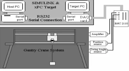
In order to evaluate the effectiveness of the proposed fuzzy logic controllers, the proposed controllers are implemented experimentally for controlling the lab-scale gantry crane system as shown schematically in Figure 6. The experimental system consists of the lab-scale gantry crane, sensors, computers and interfacing circuit. The controllers are implemented digitally in the Target PC and operated with a 1-ms sampling time. Another computer called as Host PC is needed for generating the controller algorithms. In order to interface between controllers located in the Target PC
and the lab-scale gantry crane, an
[image:4.612.84.301.433.553.2]analog-to-digital/digital-to-analog PCI-6024-E from National Instrument is used.
Figure 6 Experimental setup of the intelligent gantry crane system
Furthermore, the MathWork's
MATLAB/Simulink/RTW tool in the host PC is used for generating controller codes for real time implementation. The controller codes are then downloaded to the target PC by using xPC Target of Mathwork. By combining RTW and xPC Target, there is no need to write a low level programming language for realizing a controller and/or accessing other components such as DAQ boards. The controllers are developed in Simulink using its blocks, and then it is built so that C code is generated, compiled and finally a real-time executable code is generated and downloaded to the Target PC. In particular, the xPC Target software supports and provides built-in
drivers for many industry standard DAQ card including the PCI-6024E DAQ card by National Instrument which is used in the prototype of the intelligent gantry crane system.
The Target PC is another personal computer which is booted using xPC boot floppy disk that loads the xPC Target real-time kernel. Subsequently, the generated real-time executable code is downloaded to the Target PC via selected communication protocol without writing any low-level code. The connection between the Host PC and Target PC is accomplished either through serial (RS-232) or network (TCP/IP) communications. The communication interface have to be defined during xPC setup process in the MATLAB since the communication protocol definition is required in creating the xPC boot floppy disk for the Target PC. In the proposed system, serial communications is used since it is inexpensive, easy to install and requires only a cable for connecting serial ports of the Host PC and Target PC.
5. Performance evaluation
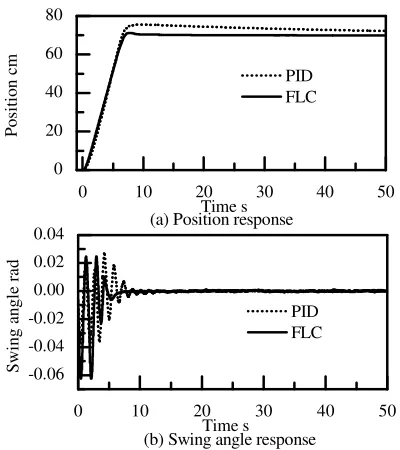
Finally the developed intelligent gantry crane system is tested and compared with the automatic gantry crane controlled by classical PID controllers. The PID controllers were designed and optimized by using the NCD blockset of MATLAB and the PID controller parameters are listed in Table 3 [8]. Figure 7 shows the responses of gantry crane controlled by the proposed controllers as well as the classical PID controllers when the 70 cm step input reference was used. The detailed performance comparisons are shown in Table 4 for position control and Table 5 for anti-swing control. Here, the performances of position control system were evaluated based on overshoot, settling time and steady state error. On the other hand, anti-swing control was based on maximum swing amplitude and settling time.
Table 3 PID controller parameters Parameters Controller
Kp Ki Kd
Position Control 2.54 7.80x10⁻⁴ 0.88
Anti-swing control 63 4.2
[image:4.612.314.533.452.506.2]0 10 20 30 40 50 0
20 40 60 80
0 10 20 30 40 50 -0.06
-0.04 -0.02 0.00 0.02 0.04
PID FLC
(a) Position response
Po
si
tio
n
cm
Time s
PID FLC
(b) Swing angle response
Sw
in
g
an
gl
e
ra
d
[image:5.612.91.291.70.295.2]Time s
[image:5.612.316.536.172.453.2]Figure 7: Experimental responses to a 70 rad step input
Table 4 Positioning performances Performances Controller
Overshoot Settling
Time Error
PID/PD 7.92 % > 50 sec -2.19 cm
Fuzzy/Fuzzy 1.71 % 6.73 sec 0.158 cm
Table 5 Positioning performances Performances Controller
Max Amplitude Settling Time
PID/PD 0.04 rad 12.7 sec
Fuzzy/Fuzzy 0.06 rad 6.73 sec
6. Robustness evaluation
Physical system in general and crane system particularly are often characterized by uncertainties of parameters. Parameter estimation error and/or parameters variations contributed to these uncertainties. In the gantry crane system, one of the major contributing factors to the uncertainty was the length variation of the string. Hence robustness of the controller is an important requirement to retain performance of the gantry crane system. The controller was robust when it has small changes in performance due to the model changes or inaccuracies. Hence, the robustness of the proposed controller has to be analyzed in order to examine its performance due to the length variation. Here, the robustness of proposed and PD controllers were examined by testing the effect of string length ( ) on the performance of the gantry crane system. Three different lengths, i.e. =20, 40, and 80 cm, were tested through simulation and the results are shown in Figure 8. Table 6 and 7 showed the performances changes due to the length variation. Figure 8(a) showed that the PD controller had small effect on the settling time and amplitude if the longer length of the string was used. However, the response became worse as soon as the shorter length of the string was used. The settling time
due to the shorter length became longer even though there was small effect on the amplitude. On contrary, Figure 8(b) showed that the fuzzy logic controller had small effect on the settling time and amplitude if the length of the string was varied compared with the PID controller. Therefore, it showed that the fuzzy logic controller was more robust to the length variations than the PID controller.
0 5 10 15
-0.03 -0.02 -0.01 0.00 0.01 0.02 0.03
length (l )=20cm length (l )=40cm length (l )=80cm
A
ng
le
ra
d
Time s
(a) PID controller robustness
0 5 10 15
-0.03 -0.02 -0.01 0.00 0.01 0.02 0.03
length (l )=20cm length (l )=40cm length (l )=80cm
A
ng
le
ra
d
Time s
(b) Fuzzy controller robustness Figure 8: Robustness Evaluation
Table 6. PID control robustness evaluation Performance changes
Length Length
variations Settling time Max
amplitude
40 cm 1 times 1 times 1 times
20 cm 0.5 times 3.9 times 1 times
80 cm 2 times 0.8 times 0.67 times
Table 7. Fuzzy control robustness evaluation Performance changes
Length Length
variations Settling time Max
amplitude
40 cm 1 times 1 times 1 times
20 cm 0.5 times 0.98 times 1 times
80 cm 2 times 1.15 times 1 times
7. Conclusions
[image:5.612.73.294.323.463.2]evaluated and was compared with the automatic gantry crane controlled with the classical PID controller. The result shows that the intelligent gantry crane system has a better performance and more robust to parameter variation compared with the automatic crane system.
Acknowledgments
This research is financially supported by Research Center, International Islamic University Malaysia.
References
[1] Omar, H.M, Control of Gantry and Tower Cranes. Ph.D. Thesis, M.S. Virginia Tech, 2003.
[2] Manson, G.A., “Time-optimal control of and
overhead crane model”, Optimal Control Applications & Methods, Vol. 3, No. 2, pp. 115-120.
[3] Auernig, J. and Troger, H., “Time optimal control of overhead cranes with Hoisting of the Load”, Automatica, Vol. 23, No. 4, (1987), pp. 437-447. [4] Karnopp, B.H., Fisher, F.E., and Yoon, B.O., “A
strategy for moving mass from one point to another”, Journal of the Franklin Institute, Vol. 329, (1992), pp. 881-892.
[5] Teo, C. L., Ong, C.J. and Xu, M., “Pulse input sequences for residual vibration reduction”, Journal of Sound and Vibration, Vol. 211, No. 2, (1998.), pp. 157-177.
[6] Singhose, W.E., Porter L.J., and Seering, W., “Input shaped of a planar gantry crane with hoisting”, Proceedings of the American Control Conference, (1997), pp. 97-100.
[7] Belanger, NM., Control Engineering: A Modern Approach, Saunders College Publishing, 1995.
[8] Wahyudi and Jalani, J., “Design and
implementation of classical PID controller for an automatic gantry crane system”, Proceedings of the International Conference on Recent Advances in Mechanical & Materials Engineering, (2005), paper no 130.
[9] Wahyudi and Jalani, J., “Design and
Implementation of Fuzzy Logic Controller for an Intelligent Gantry Crane System,” Proceedings of The 2nd International Conference on Mechatronics, (2005), pp. 345-351.
[10] Wahyudi and Jalani, J., “Modeling and parameters identification of gantry crane system”, Proceedings of the International Conference on Recent Advances in Mechanical & Materials Engineering, (2005), paper no 129.