Shear Demand of Exterior Beam Column Joint using STAAD-Pro
Rupali R. Bhoir
[1], Prof . V. G. Sayagavi
[2],Prof. N.G.Gore
[3]Prof. P. J. Salunkhe
[4]1
PG Student, Department of civil engineering, MGM’s College of Engineering & Technology, Maharashtra, India
234
Professor, Department of civil engineering, MGM’s College of Engineering & Technology, Maharashtra
---***---Abstract: Exterior Beam-Column joints are very important members in ductile detailing and are more prone to damage during earthquake. Due to complex behaviour of joint core, calculation of joint shear demand becomes critical. So confinement is provided at such joints. But this confinement leads to congestion at joints. Here in this paper an attempt is made to understand the joint core behaviour and to determine the joint shear demand by using STAAD-Pro Software V8i. For this purpose 2D framed mid and low rise buildings of earthquake zone V are considered with varying dimensional parameters. These models are modelled and designed in STAAD-Pro Software V8i with Limit State Design Method as per IS 456:2000 and detailed according to IS 13920:1993. The joint shear demand is calculated as per ACI 352-02. From those models joint shear demand is calculated and effects of various parameters on joint shear demand is briefly discussed in conclusions which can be used for the further studies.
Keywords – Exterior Beam-Column joints, ductile
detailing, and joint shear demand, STAAD-Pro
Software V8i.
Introduction
The portion of the column where beam is use to join it is called beam-column joint. Beam column joints are classified into three types based on the number of beams ending into the column
i) Interior Beam-Column joints ii) Exterior Beam-Column joints iii) Corner Beam-Column joints
Fig: 1 Types of Beam-Column Joints
(ref: ACI 352-02)
Beam-column joint is subjected to very high shear forces due to pulling of top rebar and pushing of bottom rebar’s or vice versa in the concrete structure especially during the earthquake loading. These very high shear force leads to the brittle damage, which can’t be accepted in the earthquake resistant building which has to be ductile in nature to deal with unseen forces.
Fig. 2 Congestion at the Beam-Column Joints (ref.: www.concreteconstruction.net)
To overcome this congestion problem and to get probable solution on this the joint core behaviour should be understood. Also effect of various parameters on joint shear demand should be checked.
1. Details of models
The buildings considered for this purpose are mid to low rise buildings as number of such buildings are more than high rise buildings in India. Many parameters which may influence joint shear demand are considered and buildings are modelled accordingly in STAAD-Pro software V8i. The Limit State Method is followed for the designing as per IS 456:2000. Joint shear demand is calculated as per ACI 352-02. Joints having maximum shear demand values are identified and are considered for the final conclusions.
Following are the range of parameters which has been taken for the parametric studies.
1. Story heights: It varied from 3m 3.5m and 4m in the reference buildings.
2. Number of story or height of the building: It is varied from 2nd story to 10th story with each as 3m of height.
3. Width of the bays: Bays width has chosen as 3m 4m and 5m
4. Number of the bays: number of bays has also be chosen as 3 4 and 5
5. Grade of the concrete: Grade of the concrete is taken as 30MPa, 35MPa, 40MPa, 45MPa, 50MPa, 55MPa and 60MPa.
6. Size of the beams: Size of the beam are varied from 350, 400, 450 and 500mm
7. Size of the columns: The sizes of the columns have been change from 400mm, 450mm, 500mm, 550mm and 600mm.
8. Material: M25 and Fe415 9. Earthquake Zone: V 10. Soil type: II
11. Response Reduction Factor: 5 12. Importance Factor: 1
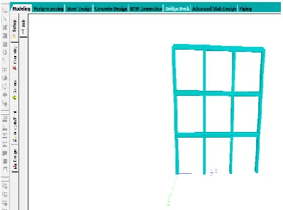
[image:2.595.347.547.368.516.2]One designed model with all these parameters is shown in figure below:
Fig. 3 3D rendered view of model in STAAD-Pro
[image:2.595.333.539.558.748.2]2.
Analysis of models
The joint shear demand is calculated as per ACI 352-02 by formula of Column shear in the joint as,
Vc=1.4 X
Where,
Mh = Hogging moment of the beam connecting to the joint.
Ms = Sagging moment of the beam connecting to the joint.
h = Height of the story.
From the equilibrium of the force in the joint, joint shear demand,
Vj = T1 + Cs + Cc - Vc Cs + Cc = T2
Vj= T1 +T2 - Vc Where,
T1 = tensile force in the bar = 1.25 x fy xAst1 T2 = tensile force in the bar = 1.25 x fy xAst2Cs = compressive force in steel
Cc = compressive force in the concrete
3. Results
The study of joint core behaviour and joint shear demand is done considering various parameters. Followings are some of the parameters which have been checked to understand their influence on the joint shear demand. Following considered parameters are discussed along with graphs to show their effects on the joint shear demand:
[image:3.595.322.554.106.352.2]1. Support conditions 2. Story height 3. Number of the bay 4. Size of the column
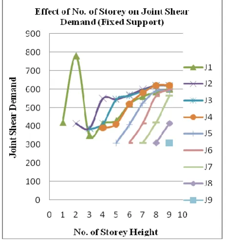
Fig. 5 Effect of No. of Storey on Joint Shear Demand (Fixed Support)
[image:3.595.332.542.528.725.2]From this graph joint named as J1 shear demand is more for only up to two-story building (fixed support) and thereafter J2 shear demand is leading. From this figure it is clear that joint shear demand of the 2nd story level is critical but the gap of difference goes on decreasing as the number of story goes on increasing.
This graph is showing the variation of shear demand due to increase in the story height of the building with the fixed support. Form this graph it seems that increasing the height of story increases the shear demand of the building.
Fig. 7 Effect of No. of Bays on Joint Shear Demand (Fixed Support)
This graph is showing the effect of number of bay on the shear demand of the joints. It is clearly seen that there is no such effect on joint shear demand with the increase in number of bays.
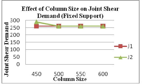
Fig. 8 Effect of Column Size on Joint Shear Demand (Fixed Support)
This graph is showing the effect of the column size on the shear demand of the joint. There is no significant effect of column size on the shear demand.
4.Conclusion
The following are point-wise conclusions which are being drawn from the proposed ExteriorBeam-Column Joints with:
1. Maximum joint shear demand is located at lower portion of building, starting from second story joint for exterior joints for the fixed support.
2. Shear forces demand increases with the increase of the Height ofStory.
3. Number of Bays and Size of Columns has no effect on the demand of the shear forces in the exterior beam-column joints.