Philip Wette
Optimizing Software-Defined Networks
using Application-Layer Knowledge
Dissertation
submitted to the
Faculty of Electrical Engineering,
Computer Science, and Mathematics
in partial fulfillment of the requirements for the degree of
Doctor rerum naturalium (Dr. rer. nat.)
Prof. Dr. Stefano Salsano, Università degli Studi di Roma Tor Vergata, Italy Additional committee members:
Prof. Dr. Friedhelm Meyer auf der Heide, Universität Paderborn, Germany Jun.-Prof. Dr. Christian Plessl, Universität Paderborn, Germany
Prof. Dr. Heike Wehrheim, Universität Paderborn, Germany Submission: June 2015
Abstract
Software-Defined Networking (SDN) is a game-changing new paradigm in telecom-munications. Using its centralized control, SDN is able to reconfigure networks on time-scales of milliseconds instead of seconds or minutes, opening up possibilities for traffic engineering undreamed-of before.
This thesis studies the question “To which extent does application-layer knowledge help traffic engineering to increase network performance?”. To this end, it considers the two network typescircuit-switched networks and packet-switched networks. Both types have different properties and feature different possibilities for reconfiguration. This is why this thesis approaches both of them individually, in very different ways. Prior to communication in a circuit-switched network, a dedicated circuit between both communication partners has to be established. This circuit is used exclusively, ensuring certain properties such as usable data rate or latency. In contrast, in the packet-switched domain, a shared medium is used for communication. Data is trans-ferred using (small) data packets which are routed independently of each other over the shared network.
As a showcase for circuit-switched networks, this thesis considers optical wide area networks (WAN) and for packet-switched networks data-center (DC) networks are examined. WANs are covering large areas such as entire countries. They usually employ optical wavelength division multiplexing (WDM) technology providing high data rates to interconnect various smaller, diverse networks. DC networks, on the other hand, are deployed on a much smaller spatial area interconnecting servers owned by one operator.
To include application-layer knowledge into the optimization of WDM networks, first a new type of Routing and Wavelength Assignment (RWA) algorithm is proposed. The algorithm provides an interface between the management layer of a WDM net-work and the applications running on top of it. In a subsequent step, this interface is used to create an algorithm approaching the virtual topology design problem for software-defined IP-over-WDM networks. The algorithm leverages knowledge from the application layer to significantly increase the performance of optical WDM WANs. To approach DC networks, first the necessary tools for experimental evaluation of traffic engineering in such networks had to be developed. MaxiNet is presented, which is a highly scalable emulation environment for SDNs. To mimic highly realistic DC traffic, DCT2Gen was created which is the first publicly available generator for
SDN enabled data-center networks having higher performance than state-of-the-art TE techniques. At the showcase of HybridTE, this thesis shows how different qualities of information impact the quality of the traffic engineering scheme. This makes this thesis the first to show the relation between the amount of explicit information and the performance gained by this information in a realistic data-center environment.
Zusammenfassung
Software-Defined Networking (SDN) ist ein neues, wegweisendes Paradigma um Netze zu kontrollieren. Durch seine zentralisierte Kontrolle können Netze auf Zeitskalen von Millisekunden anstelle von Sekunden oder Minuten rekonfiguriert werden. Dies eröffnet vollkommen neue Möglichkeiten um Traffic Engineering zu betreiben.
Diese Dissertation widmet sich der Frage: „Welchen Nutzen besitzt Anwendungswis-sen für Traffic Engineering um die Leistungsfähigkeit von Netzen zu erhöhen?”. Um diese Frage zu beantworten, beschäftigt sich diese Arbeit mit leitungsvermitteln-den, sowie mit paketvermittelnden Netzen. Beide Netztypen haben unterschiedliche Eigenschaften und bieten unterschiedlichste Möglichkeiten der Rekonfiguration. Aus diesem Grund werden beide Typen individuell, jeweils mit verschiedenen Metho-den, untersucht. Bevor Kommunikation in einem leitungsvermittelnden Netz möglich ist, muss zunächst zwischen jedem Kommunikationspaar ein dedizierter Übertra-gungskanal vermittelt werden. Jeder ÜbertraÜbertra-gungskanal wird exklusiv genutzt. Dies stellt gewisse Eigenschaften der Kommunikation sicher, wie eine feste Latenz oder eine gewisse Datenrate. Im Gegensatz dazu wird in paketvermittelnden Netzen ein gemeinsam genutztes Medium verwendet in dem keine Garantien bezüglich der Kom-munikationseigenschaften existieren. Daten werden in (kleinen) Paketen übertragen die unabhängig voneinander durch das Netz geleitet werden.
Als Beispiel für ein leitungsvermittelndes Netz dient in dieser Arbeit ein Weit-verkehrsnetz (WAN). Als Beispiel für ein paketvermittelndes Netz wird ein Rechen-zentrumsnetz genutzt. WANs decken sehr große Areale ab, wie beispielsweise ganze Länder. Es handelt sich dabei in der Regel um Glasfasernetze, die die Wavelength Division Multiplexing (WDM) Technologie verwenden. WANs werden in der Regel genutzt, um verschiedenste, kleinere Netze miteinander zu verbinden. Rechenzen-trumsnetze decken eine wesentlich kleinere Fläche ab und verbinden eine Menge von Servern miteinander.
Um Anwendungswissen in der Optimierung von WDM Netzen zu nutzen, wird im Rahmen dieser Arbeit zunächst ein neuer Routing and Wavelength Assignment Al-gorithmus entwickelt. Dieser AlAl-gorithmus dient als Schnittstelle zwischen der Netz-kontrollschicht und den Anwendungen, die das Netz zum Datenaustausch nutzen. Anschließend wird diese Schnittstelle von einem weiteren Algorithmus genutzt, der das Virtual Topology Design Problem von IP-over-WDM Netzen löst. Dieser Al-gorithmus nutzt Anwendungswissen und ist in der Lage, die Leistungsfähigkeit von
mussten zunächst die entsprechenden Werkzeuge entwickelt werden. Eines dieser Werkzeuge istMaxiNet, eine hochgradig skalierbare Emulationsumgebung für SDNs. Für die Evaluation von neuen Traffic Engineering Techniken in Rechenzentrumsnetzen werden realistische Verkehrsmuster benötigt. Aus diesem Grund wurde DCT2Gen
entwickelt, der ersteöffentlich verfügbare Generator für realitätsnahe Verkehrsmuster aus Rechenzentrumsnetzen.
MaxiNet und DCT2Gen wurden anschließend verwendet, um HybridTE zu
evalu-ieren. HybridTE ist ein neuer Routingalgorithmus, der Anwendungswissen ausnutzt, um leistungsfähige Rechenzentren mit Hilfe von preiswerten Netzkomponenten zu re-alisieren. Am Beispiel von HybridTE zeigt diese Arbeit, welchen Einfluss verschiedene Qualitäten von Anwendungswissen auf die resultierende Güte des Traffic Engineer-ings haben. So ist diese Arbeit die erste, die den Zusammenhang zwischen der Menge von verfügbaren, expliziten Informationen und der daraus entstehenden Güte in einer realistischen Rechenzentrumsumgebung zeigt.
Acknowledgment
I would like to thank Prof. Dr. Holger Karl for all the support and advice during the last years and Prof. Dr. Stefano Salsano for serving as a referee. Working at the Computer Networks Group was always fun; thanks to all my colleagues for making this a great time. I will never forget all the interesting and fruitful discussions, especially with my officemate Arne Schwabe. Thank you, Arne. In addition, I would like to thank Felix Wallaschek who contributed a lot of brilliant program code to the MaxiNet project.
This all would not have been possible without the constant mental support of my family. Thank you for always believing in me. I would like to especially thank my fiancée, Susanne, and my parents, Beatrice and Siegfried, for their support and patience throughout the whole course of my studies.
Contents
1. Introduction 1
1.1. Structure of this Thesis . . . 3
1.2. Contributions . . . 5 2. Background 9 2.1. Optical Networks . . . 9 2.2. Software-Defined Networking . . . 14 2.3. Network Characteristics . . . 17
I.
Circuit Switching
21
3. A Preemptive Routing and Wavelength Allocation Algorithm 23 3.1. Introduction . . . 243.2. Related Work . . . 25
3.3. Generic Graph model . . . 27
3.4. Routing and wavelength assignment . . . 28
3.5. Simulation . . . 35
3.6. Conclusion . . . 40
4. Selfish Virtual Topology Reconfiguration in IP-over-WDM 43 4.1. Introduction . . . 44
4.2. Related Work . . . 45
4.3. Software Defined IP-over-WDM Networks . . . 46
4.4. Selfish Virtual Topology Reconfiguration . . . 48
4.5. Simulation . . . 49
4.6. Conclusion . . . 56
II. Packet Switching
57
5. A Low-Cost, Software-Defined Data-Center Network 59 5.1. Introduction . . . 595.2. Related Work . . . 61 5.3. HybridTE . . . 62 5.4. Evaluation . . . 66 5.5. Conclusion . . . 76 6. Elephant Detection 77 6.1. Introduction . . . 77
6.2. OpenFlow Packet Sampling Extension . . . 78
6.3. Using Packet Sampling for Elephant Detection . . . 80
6.4. Evaluation . . . 81
6.5. Conclusion . . . 82
III.Emulation Tools
85
7. MaxiNet: A Scalable Network Emulator 87 7.1. Introduction . . . 877.2. Related Work . . . 89
7.3. MaxiNet . . . 90
7.4. Performance Evaluation of MaxiNet . . . 92
7.5. NetSLS: A MaxiNet Application . . . 101
7.6. Conclusion . . . 105
8. DCT2Gen: A Traffic Generator for Data Centers 107 8.1. Introduction . . . 107
8.2. Related Work . . . 110
8.3. Traffic Properties . . . 112
8.4. Architecture of DCT2Gen . . . . 115
8.5. Deconvolving Traffic Matrix Entries . . . 118
8.6. Generating Traffic Matrices . . . 122
8.7. Generating TCP Flows . . . 128
8.8. Empirical Evaluation . . . 133
8.9. Conclusion . . . 140
9. Conclusion and Future Work 141 9.1. Conclusion . . . 141
9.2. Future Work . . . 142
List of Figures
2.1. Model of an optical WDM network with three established lightpaths. 10
2.2. Simplified working principle of a ROADM. . . 11
2.3. The offline routing and wavelength allocation problem. . . 12
2.4. The online routing and wavelength allocation problem. . . 13
2.5. The physical and logical topology of an optical WDM network. . . 13
2.6. Topology of the janos-us network. . . 17
2.7. Schematic view of a fat tree topology. . . 18
2.8. Schematic view of a clos-like topology. . . 19
3.1. Workflow of our proposed RWA algorithm. . . 25
3.2. Layered graph with W wavelengths. . . 28
3.3. Flowchart of the proposed RWA algorithm. . . 30
3.4. Construction of the conflict graph GC from a lightpath configuration. 31 3.5. Rerouting lightpaths. . . 33
3.6. Unsuccessful cleanup. . . 33
3.7. Influence of con the blocking probability. . . 37
3.8. Influence of cleanup on the blocking probability. . . 37
3.9. Influence of the holding time on the blocking probability. . . 38
3.10. Average hop count of established lightpaths. . . 38
3.11. Success rate of the rerouting operation. . . 39
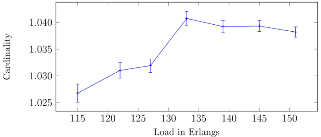
3.12. Cardinality of each set of rerouting candidates. . . 39
3.13. Blocking probability of different configurations. . . 40
4.1. SDN-over-WDM Network. . . 46
4.2. Germany50 network with 50 nodes and 88 links. . . 49
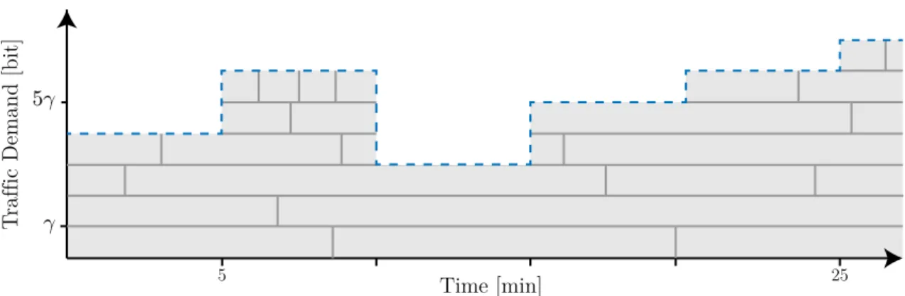
4.3. Total traffic demand over a 24-hour period. . . 50
4.4. Exemplary flow schedule for a pair of nodes. . . 51
4.5. Throughput over different load levels. . . 53
4.6. Maximum used physical interfaces at a single switch. . . 53
4.7. Average flow entries per SDN switch. . . 54
4.8. Maximum flow entries used at a single SDN switch. . . 54
4.9. Throughput over different flow size limits. . . 54
4.11. Achieved throughput over iterations. . . 55
5.1. Clos-like data-center topology with an exemplary forwarding tree. . . 63
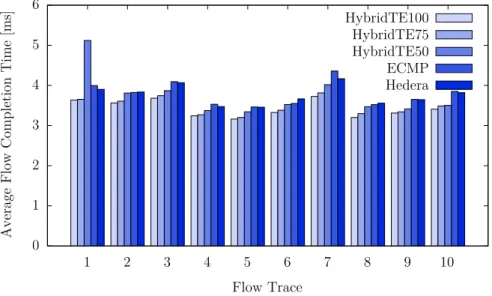
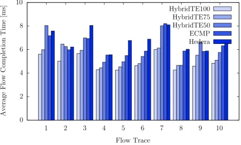
5.2. Average flow-completion time over all ten flow traces on load level 1. . 68
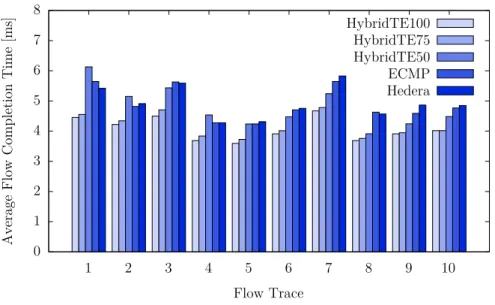
5.3. Average flow-completion time over all ten flow traces on load level 1.5. 69 5.4. Average flow-completion time over all ten flow traces on load level 1.75. 70 5.5. Average flow-completion time over all ten flow traces on load level 2. . 70
5.6. Average flow completion time created by HybridTE100. . . 71
5.7. Reduction of the average flow completion time created by HybridTE. 72 5.8. Maximum number of elephants on load level 1. . . 74
5.9. Maximum number of elephants on load level 1.5. . . 74
5.10. Maximum number of elephants on load level 1.75. . . 75
5.11. Maximum number of elephants on load level 2. . . 75
6.1. ofp_flow_sampling_request message. . . 79
6.2. ofp_sample_flow message. . . 79
6.3. The token bucket algorithm for packet sampling. . . 80
6.4. Throughput over different sampling rates . . . 80
6.5. Rates of false negatives for different parameter sets. . . 83
6.6. Reporting delay for different parameter sets. . . 83
6.7. Rates of false positives for different parameter sets . . . 83
7.1. Schematic view of MaxiNet. . . 91
7.2. Minimal example experiment using the MaxiNet Python API. . . 92
7.3. One switch pair consisting of 2 switches and 2 hosts connected in a line. 93 7.4. Required dilation factor when emulating on a single physical machine. 93 7.5. Speedup gained from an increasing number of workers. . . 94
7.6. Distribution of forwarding delays. . . 95
7.7. Sketch of the emulated Clos-like topology. . . 96
7.8. Distribution of flow completion times. . . 96
7.9. QQ-plot of flow completion times. . . 97
7.10. Aggregate traffic demand used in the large-scale experiment. . . 98
7.11. CPU utilization and network usage of the OpenFlow controller. . . . 99
7.12. Average CPU usage of the workers during the experiment. . . 100
7.13. Average network usage of the workers during the experiment. . . 100
7.14. Schematic view of SLS. . . 102
7.15. Schematic view on NetSLS. . . 104
8.1. High-level overview of DCT2Gens work flow. . . . 108
8.2. Relationship between Layer 2 flows, ACKs, and payload flows. . . 114
8.3. Architectural overview of DCT2Gen. . . 118
8.4. Payload bytes per ACK packet over different flow sizes. . . 120
List of Figures
8.6. Run time of ILP 1. . . 126
8.7. Distribution of node degrees. . . 128
8.8. Algorithm for selecting s-d pairs for flows. . . 131
8.9. Topsøe distance of flow assignment methods. . . 132
8.10. Sketch of the Clos-like topology that was used in our experiments. . . 134
8.11. Comparison between Sgen and Sobs. . . 136
8.12. Comparison between Ngeninter and Nobsinter. . . 136
8.13. QQ-plot of Ngeninter and Nobs inter. . . 137
8.14. Comparison between Nobs intra and N gen intra. . . 137 8.15. QQ-plot of Nobs intra and N gen intra. . . 137
8.16. Comparison between Bobs intra and B gen intra. . . 138
8.17. QQ-plot of Bobsintra and Bgenintra. . . 138
8.18. Comparison between Bobsinter and Bgeninter. . . 139
8.19. QQ-plot of Bobs inter and B gen inter. . . 139
1
Introduction
Cisco’s Visual Networking Index proclaimed the Zettabyte Era for 2016 because the annually transferred amount of global IP traffic will—for the first time in history— exceed a zettabyte (1021 bytes); even growing to 1.6 zettabytes in 2018. In turn, the
Internet’s infrastructure has to grow at a rapid pace; not only in quantity but also in quality. This thesis shows how to increase the efficiency of networking infrastructure by adding an intelligent interplay between the applications that generate traffic and the network infrastructure that transports this traffic.
This interplay leads to a new form of traffic engineering (TE) that tightly couples applications and network management, creating networks that adapt to application needs in virtually no time. In contrast to prior work, where applications adapt to the network infrastructure, this work develops networks that adapt to applications needs. The enabling technology here is Software-Defined Networking (SDN). With SDN, it is possible to define the behavior of a whole network using a central software component. This software component has full access to all internals of the physical network infrastructure enabling the redefinition of the behavior of any device on very short time scales. The possibilities for reconfiguration are so wide that each single flow in the network can be routed individually with routing paths computed using global knowledge.
The Internet consists of a large number of interconnected, autonomously managed networks. These networks fulfill different tasks and are built from different technolo-gies using different methodolotechnolo-gies. To scale up the Internet, all of these networks have to be scaled. The two main classes of networking methodologies are circuit-switched and packet-switched networks. Circuit-switched networks allocate resources exclusively for each pair of communicating endpoints. Exclusive allocation guarantees
certain properties such as latency and throughput. In packet switched networks, all links are shared between all communicating pairs which means that the data transfers influence each other, hence no strict guarantees can be given for any transfer.
Due to the different technologies, methodologies, and properties of the networks, the possibilities for reconfiguration are diverse. This is why this thesis approaches both methods, circuit-switching and packet-switching, on their own. As a showcase for circuit-switched networks, wide area networks (WAN) are used. WANs span across large spacial areas such a entire countries or continents and interconnect other networks. For packet-switched networks, data-center (DC) networks are inspected, covering only a very small spacial area, directly interconnecting thousands of servers with each other.
Modern WANs employ optical Wavelength Division Multiplexing (WDM) technol-ogy that is mainly used to carry IP traffic directly without any other layers such as SONET or SDH in between. This is then called an IP-over-WDM network where mul-tiple IP routers are interconnected using circuits established over the WDM network. Depending on the choice of the circuits, the neighborhood of the IP routers changes; communication between two routers that are not directly connected either requires a new circuit or a routing path over other routers. Obviously, for small amounts of traffic between a pair of routers a direct circuit is not necessary, however, for large amounts of data it might be beneficial to establish a new circuit, reducing traffic on other links. Obviously, the largest potential for reconfiguration of such a network is the choice of the circuits. To increase the efficiency of IP-over-WDM networks, this thesis proposes a scalable algorithm that at any time identifies which circuits to establish between which nodes in the network and which resources to allocate to es-tablish these circuits. To find out which set of new circuits to eses-tablish and which set of old circuits to remove, a feedback loop between the IP routing layer (which in this case is the application using the network) and the WDM network control is created. Evaluation through a simulation study shows that by establishing the feedback loop to leverage knowledge from the application layer, the congestion in the network can be reduced by up to 50 % in the inspected scenarios.
While in circuit-switched networks the neighborhood can be changed by adding and removing new circuits, the topology of a packet-switched network is fixed and cannot be changed (apart from physical changes, i.e., laying new cables). The largest degree of freedom in such networks is routing. In traditional data-center networks, routing is calculated in a distributed fashion. The state of the art for data-center routing today is Equal-Cost-Multipath-Routing (ECMP). Here, each flow is assigned a random shortest path through the network. In symmetric networks, like data centers, ECMP spreads the flows equally over all links. If all flows had the same size, this would lead to equal load distribution on all links. If, however, multiple large flows are assigned to the same link, congestion occurs while there might be alternative paths with free residual data rate. In this situation, a load-aware routing algorithm
1.1. Structure of this Thesis
with global knowledge of the current network state can help resolve congestion. This thesis shows how to design and evaluate a load-aware routing algorithm for data centers consisting of low-cost SDN network equipment. Such equipment has strong limitations on both its flow-table sizes and its processing capabilities. Evaluation shows that using the load-aware routing algorithm, the flow completion times can be reduced by up to 14.9 % compared to ECMP in a data-center environment.
1.1. Structure of this Thesis
This thesis is divided into the three different parts Circuit Switching, Packet
Switching, and Emulation Tools. The first part describes a technique that
al-lows optical WDM networks to automatically adapt to the applications running on top of them. This is different from what happens today where applications adapt their communication structure to the structure and properties of the underlying net-work. The peer-to-peer network Gnutella 0.6 [KM02] was one of the first applications with such an adaption process. Recently, the IETF published the protocol draft ALTO (Application-Layer Traffic Optimization) [APY+14] to provide applications
with topology information of ISP networks. This enables applications to adapt their communication patterns to better fit to the underlying network. Note that this thesis investigates the problem the other way around. Here, networks are built that adapt to the communication structure of the applications. For the adaption process, in-formation about the desired communication structure of the applications need to be available at the management plane of the network.
Chapter 3 presents a novel Routing and Wavelength Assignment (RWA) algo-rithm for optical WDM networks. The algoalgo-rithm exposes an interface through which requests for lightpaths can be submitted. In case enough resources are available for the new lightpath, it is created. Otherwise, the algorithm computes sets of light-paths which—in case they were to be removed from the network—yield enough free resources to fulfill the lightpath request. These sets are then passed back to the re-quester of the lightpath who can now choose which set to be removed, if any. The chapter first introduces a graph model along with the description and a complexity analysis of the novel RWA algorithm. To find out about the efficiency of the RWA algorithm in a WAN scenario, a simulation study is conducted.
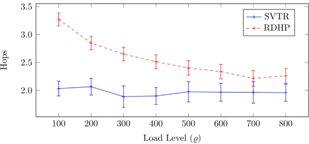
Chapter 4 shows how the RWA algorithm developed in Chapter 3 can be used to build a WAN adapting to the requirements of the application running on top of it. A distributed algorithm for an IP-over-WDM network is presented where each IP router acts independently and selfishly. The approach is called Selfish Virtual Topology Reconfiguration (SVTR) and comprises three simple actions to adapt the virtual topology of the network to the requirements of the application. Evaluation shows that SVTR performs significantly better than a state-of-the-art virtual topology design algorithm which does not use any information from the application layer. The
evaluation was conducted through a simulation study of the Deutsche Forschungsnetz (DFN) WAN topology along with real-world traffic patterns recorded in that network. The second part of this thesis entitled Packet Switchingfocuses on routing in packet-switched networks. The leading question here is how much value application-layer knowledge has for traffic engineering in a data-center context.
Chapter 5presents a routing algorithm called HybridTE which targets data-center networks. HybridTE distinguishes between small and large flows and handles them differently. To this end, HybridTE requires information about large flows which are either reported directly from the applications to HybridTE or estimated using so calledelephant detectors (large flows as calledelephants in the literature). Using this information, HybridTE has very low requirements on the switches while performing better than state-of-the-art traffic engineering techniques which have much higher requirements on the hardware. To study the effect of uncertain information on the quality of HybridTE (which might be induced by the elephant detector), different percentages of false positives, false negatives and different delays between the start of a large flow and its report to HybridTE are used in the evaluation. The results show that HybridTE is resilient against large numbers of false positives and that it still performs well even with 50% false negatives and reporting delays of up to one second.
Chapter 6 evaluates the quality of simple packet sampling as a possible elephant detection technique for data centers. To this end, first an extension for OpenFlow is presented. Using this extension, packet sampling capabilities of the switches can be controlled. Having control over packet sampling, it is possible to build a very simple elephant detector residing inside the OpenFlow controller. This chapter evaluates the quality of the generated information and concludes how valuable this information is for HybridTE.
While simulation is a reasonable and widely used technique for evaluation of circuit-switched networks,emulation is more suited to conduct research on packet-switched, low-latency networks such as data-center networks. Emulation is much more detailed than simulation, hence more realistic. High realism is very important for the evalu-ation of novel routing and traffic engineering algorithms for data centers because of the wide variety of effects caused by technical details such as a real TCP stack im-plementation. Although these effects are presumably negligible for large long-lasting flows, they have an essential influence on very small flows carrying only a few bytes. Traffic in data centers mainly consists of very small flows, which is why emulation is crucial in this scenario. Unfortunately, there was no network emulator available for emulating large networks such as a data center. Hence, to conduct the research presented in the second part of this theses, first the necessary tools had to be devel-oped. These tools are presented in the third part of this thesis entitled Emulation
1.2. Contributions
Chapter 7presents a highly scalable, distributed network emulator calledMaxiNet. MaxiNet extends the famous Mininet emulation environment [LHM10] to span the emulation across several physical machines. This allows to emulate very large SDN networks on only a small number of physical machines each of which is calledworker. In MaxiNet, each of these workers runs a Mininet instance and only emulates a part of the whole network. Switches and hosts are interconnected using GRE tunnels across different workers. MaxiNet provides a centralized API for controlling the emu-lation. The chapter discusses the design and presents an evaluation of the scalability of MaxiNet. The emulation showed that it is possible to emulate a mid-sized data center consisting of 3,600 hosts using only 16 workers in acceptable time.
Chapter 8 explains the design of DCT2Gen, a highly realistic traffic generator for
data-center traffic. To conduct highly realistic evaluations, a network emulator alone is not sufficient. The emulated traffic needs to be realistic, too. Unfortunately, no traffic traces from real data centers are publicly available. The two studies [BAM10, KSG+09] published detailed statistical properties of data-center traffic on Ethernet level. DCT2Gen takes these properties to create a schedule of TCP connections
between a set of hosts. When this schedule is played out at a (emulated) data center, this creates Ethernet traffic with the same properties as given before. The chapter discusses the problems when computing such a schedule and explains the techniques required for solving them. Based on that, the design of DCT2Gen is presented which is subsequently evaluated through MaxiNet emulations.
1.2. Contributions
The contents presented in this thesis were all developed in the time between October 2011 and March 2015. During that time, I authored nine research papers from which, by the time of writing, seven papers are published in peer-reviewed conference pro-ceedings. Although I am the main author of all nine papers, in the remainder of this thesis I will change to first person plural to indicate that the corresponding findings are the result of joint work.
In addition, three open-source projects emerged from the work presented in this the-sis, namely MaxiNet (Chapter 7), DCT2Gen (Chapter 8), and NetSLS (Section 7.5).
These projects can be found online under the URLs listed in Table 1.1. Chapter 3 is based on the papers
• P. Wette and H. Karl. Using Application Layer Knowledge in Routing and Wavelength Assignment Algorithms. InProceedings of the IEEE International Conference on Communications (ICC), 2014
• P. Wette and H. Karl. Incorporating Feedback from Application Layer into Routing and Wavelength Assignment Algorithms. In Proceedings of the IEEE International Conference on Computer Communications (INFOCOM), 2013
Table 1.1.: URLs of the open-source projects emerged from this thesis. MaxiNet https://www.cs.uni-paderborn.de/?id=maxinet
https://github.com/MaxiNet/MaxiNet
DCT2Gen https://www.cs.uni-paderborn.de/?id=dct2gen
NetSLS https://github.com/wette/netSLS
Chapter 4is based on the paper
• P. Wette and H. Karl. On the Quality of Selfish Virtual Topology Reconfigura-tion in IP-over-WDM Networks. InProceedings of the 19th IEEE Int. Workshop on Local and Metropolitan Area Networks, 2013
Chapter 5is based on the paper
• P. Wette and H. Karl. HybridTE: Traffic Engineering for Very Low-Cost Software-Defined Data-Center Networks.arXiv preprint arXiv:1503.04317, 2015. (submitted to the European Workshop on Software Defined Networks)
Chapter 6uses parts of the paper
• P. Wette and H. Karl. Which Flows Are Hiding Behind My Wildcard Rule? Adding Packet Sampling to OpenFlow. In Proceedings of the ACM SIGCOMM 2013 conference on Applications, technologies, architectures, and protocols for computer communication, 2013
Chapter 7is based on the papers
• P. Wette, M. Dräxler, A. Schwabe, F. Wallaschek, M. Hassan Zahraee, and H. Karl. MaxiNet: Distributed Emulation of Software-Defined Networks. In
IFIP Networking Conference, 2014
• P. Wette, A. Schwabe, M. Splietker, and H. Karl. Extending Hadoop’s Yarn Scheduler Load Simulator with a Highly Realistic Network & Traffic Model. In
Proceedings of the 1st IEEE Conference on Network Softwarization, 2015 Chapter 8is based on the paper
• P. Wette and H. Karl. DCT2Gen: A Versatile TCP Traffic Generator for Data
Centers. arXiv preprint arXiv:1409.2246, 2014. (submitted to Elsevier Journal on Computer Communications)
1.2. Contributions
• P. Wette, M. Dräxler, A. Schwabe, F. Wallaschek, M. Hassan Zahraee, and H. Karl. MaxiNet: Distributed Emulation of Software-Defined Networks. In
2
Background
This chapter provides a brief overview of the basic terms and network technologies used throughput this thesis. In Section 2.1 the basics of modern optical networks are explained. Deep technical details which are not necessary to understand the concepts presented in this thesis are omitted and can be found in [RSS09]. Software-defined networking and one of its implementations for packet-switched networks, OpenFlow, is introduced in Section 2.2. Section 2.3 discusses properties of wide-area and data-center networks. This chapter does not intend to discuss related or competing work; this is done in the corresponding chapters of this thesis.
2.1. Optical Networks
Optical networks use light as a communication medium. As opposed to free-space optical communication, the optical networks considered in this thesis are communi-cating through fibers. These fibers are interconnecting optical network equipment. As the usable bandwidth in fibers is very large, very high data rates can be achieved. In addition, the attenuation in optical fibers is very low allowing large distances be-tween network equipment. Both aspects favor optical networks as the key technology used in modern wide-area networks.
Before a pair of nodes is able to communicate via an optical network, the two communication partners need to setup what we call a circuit. A circuit is a pair of
lightpaths between the two partners; one for each direction of the communication. A lightpath is a path through the optical network interconnecting its two endpoints. For technical reasons one single fiber can only be used unidirectional which is why fibers
are commonly deployed in pairs; one fiber for each direction. If not stated otherwise, with the word fiber we always refer to such a pair of fibers. In turn, in this thesis lightpaths are always created in pairs, i.e., constructing a lightpath from node u to nodev always implies the construction of a lightpath from v tou over the same path in the network. This makes model building simpler as with this assumption both fibers and lightpaths can be used for bidirectional communication.
2.1.1. Wavelength Division Multiplexing
In optical Wavelenth Division Multiplexing (WDM) networks, the available band-width on the fibers is divided intoW independent communication channels denoted
asΛ = (λ1, λ2, ..., λW) for some fixed W ∈N. These channels are called wavelengths.
Using different wavelengths allows concurrent data transmissions over the same fiber without causing any interference. Nevertheless, no two lightpaths must share the same wavelength on any shared fiber. In WDM, very high data rates can still be achieved; 10 Gbps and beyond per wavelength are not uncommon.
A
B
C
Figure 2.1.: Model of an optical WDM network with three established lightpaths.
Recalling the prior example, Figure 2.1 shows a small WDM network between three nodes. The example shows lightpaths between A and B, B and C, and A and C. As all lightpaths are using different wavelengths, there is no interference while all three nodes can communicate concurrently.
One of the more sophisticated optical network equipment used in modern WDM networks is called reconfigurable optical add-drop multiplexer (ROADM). Figure 2.2 shows the working principle of a ROADM with three connected fibers and one optical-to-electrical converter. Each attached fiber ends in a prism that breaks the light into its different wavelengths. From the prisms, the wavelengths encounter wavelength selective mirrors whose angle can be automatically adjusted to route the wavelength to the according outgoing fiber. Optical-to-electrical converters can be used to termi-nate a lightpath at a ROADM. In that case, the signal is converted and forwarded in the electrical domain to its final destination. Electrical-to-optical converters (missing in the figure) are used to create an optical signal corresponding to a given electrical signal.
ROADMs can also have the ability to convert between wavelengths. Thus, a signal arriving at wavelengthλ1 on one fiber can be converted to wavelengthλ2 and
2.1. Optical Networks
Optical-to-electrical converter
N
W E
S
Wavelength selective mirror
Prism
Fiber
Figure 2.2.: Simplified working principle of a ROADM.
optical domain1 which means no additional latency is induced by such operations. Depending on the particular ROADM design it might not be possible to convert between all wavelengths on all fibers; this is called limited wavelength conversion ca-pabilities as opposed to full wavelength conversion caca-pabilities where any conversion is possible. As with wavelengths, a ROADM might not be able to redirect light from every input port to every output port. This is referred to as limited light-switching (LS) capabilities [RSS09].
2.1.2. The Routing and Wavelength Allocation Problem
Whenever a new lightpath is to be added to a WDM network, this lightpath requires a path between its endpoints along with a wavelength for each fiber on that path. The problem of finding both a path and the corresponding wavelengths is called the
Routing and Wavelength Allocation Problem (RWA Problem) [RSS09]. This problem has an online and an offline variant.
We define the offline Routing and Wavelength Allocation Problem as follows. Given:
• An undirected simple graph G = (V, E) representing the set V of ROADMs and the setE ⊆V ×V of fibers
• A setΛ ={λ1, λ2, ..., λn} representing the usable wavelengths per fiber
• A setL⊆V ×V of lightpath requests
the offline Routing and Wavelength Allocation Problem asks for a route for each
1Although it is possible to conduct wavelength conversion in the optical domain, current commercial
products stick to the optical-electrical-optical paradigm [RSS09]; it can be assumed that in the future all-optical conversion will be used in commercial products, too.
physical topology logical topology
u
v
w
u
v
w
?
x
y
x
y
Figure 2.3.: The offline routing and wavelength allocation problem.
lightpathl ∈Lalong with a wavelength for each fiber on the route such that no two lightpaths use the same wavelength on any shared fiber. The problem is depicted in Figure 2.3 where the right-hand side depicts the demanded lightpaths and the left-hand side the physical topology.
The offline RWA problem can be reduced to finding the chromatic number of a graph [CGK92] and is thus N P-complete. As the problem is highly relevant for running WDM networks efficiently, a lot of heuristics [XSBM08, WLYX07, WWH+11, SBCL01, ZPC+08] have been proposed.
While the offline variant of the problem asks to build a new network of lightpaths from scratch every time a new lightpath is requested, the online version of the problem asks to add a new lightpath to anexisting set of already established lightpaths where the existing lightpaths must neither be rerouted nor allocated to different wavelengths.
The online Routing and Wavelength Allocation Problem is defined as follows. Given:
• An undirected simple graph G = (V, E) representing the set V of ROADMs and the set E ⊆V ×V of fibers
• A set Λ ={λ1, λ2, ..., λn} representing the valid wavelengths per fiber
• A set L⊆ P(E)× P(Λ) of established lightpaths
• A lightpath request between nodes u, v ∈V
find a route and wavelength allocation for a new lightpath betweenuand v such that no two lightpaths use the same wavelength on any shared fiber. It is not allowed to modify any of the lightpaths l ∈L (in terms of the paths or assigned wavelengths). This is depicted in Figure 2.4. The dashed line between v and y on the right-hand side is the requested lightpath. The arrows on the left is the set of already established lightpaths. In the standard online RWA problem, a valid solution must contain all lightpathsl ∈Land the newly requested lightpath. In thepreemptive RWA problem, not all l ∈ L must exist in a valid solution, making is possible to preempt already existing lightpaths to free resources that can subsequently be used to establish the requested lightpath. But one should note that depending on the applications using the network, preempting a lightpath potentially has a negative effect on the performance
2.1. Optical Networks
physical topology logical topology
u
v
x
w
u
v
w
?
y
x
y
Figure 2.4.: The online routing and wavelength allocation problem. of these applications.
A single instance of the online RWA problem is solvable in polynomial time. How-ever, if we consider adding a series of lightpaths subsequently to the network using the polynomial online RWA algorithm, this solves the offline RWA problem. Hence, solving a series of the online RWA problem isN P-hard.
2.1.3. Virtual Topology Design
As stated in Section 2.1.1, prior to communicating over a WDM network a lightpath has be be established between the two communicating partners. Thus, the set of established lightpaths in the network determines who can directly talk to whom. Figure 2.5 visualizes this for a small example. The lower layer depicts the ROADMs and fibers of the network; we call it the physical topology. The colored arrows in the physical topology are the established lightpaths. These lightpaths define the logical topology of the network. Each node of the physical topology has a corresponding node in the logical topology. The set of edges in the logical topology is defined as the set of endpoints of the established lightpaths in the underlying physical topology.
Physical Topology & Lightpaths Logical Topology
The virtual topology design problem (VTD problem) asks for a set of realizable lightpaths defining a logical topology (over a given physical topology) that has certain properties. Commonly, these properties include, but are not limited to:
• The maximum perceived latency for any pair of nodes
• The diameter of the network
• Support for a certain traffic pattern without being congested
• Maximum node degree in the virtual topology
The desired properties of the logical topology are given as an input to the VTD problem. Note that solving the VTD problem requires solving the RWA problem as well which in turn means that VTD is N P-hard [DR00]. There are a couple of heuristics solving the VTD problem. For a survey, see [DR00].
2.2. Software-Defined Networking
The termSoftware-Defined Networking (SDN) is primarily a marketing term that has no common technical definition in the scientific community. Driven by the control protocolOpenFlow, SDN recently became very popular for packet-switching networks. As of today, every large network equipment vendor has SDN products controllable via OpenFlow.
2.2.1. Characterization
For the scope of this thesis, SDN is characterized by the following three points:
• Separation of forwarding plane and control plane
• (Logically) centralized control through a controller-to-device protocol (such as OpenFlow)
• Capability to programmatically influence the behavior of the network Separation of Forwarding Plane and Control Plane
Traditional network elements such as routers and switches consist of a forwarding plane and a control plane. As the name says, the forwarding plane is responsible for forwarding packets. To this end, it maintains a forwarding table. Whenever a packet arrives at the network element, the corresponding actions to be taken for the packet are looked up in the forwarding table. Possible actions include, but are not limited to, a port to output the packet on, rewriting IP or Ethernet header fields, or pushing/popping Multiprotocol Label Switching (MPLS) labels to the packet.
Whenever there is no entry in the forwarding table for a packet, the control plane is asked for the desired actions which are subsequently stored in the forwarding table. Depending on the desired routing behavior of the network, the control plane needs
2.2. Software-Defined Networking
to run different routing algorithms to compute the actions. As traditional network elements do not have centralized control, routing algorithms are distributed.
To get as much logic as possible off the network elements, an SDN network element only consists of the forwarding plane and its forwarding table. This is why they are called SDN forwarding element, or short SDN switch. The forwarding table is exposed by an API to external devices. In SDN, forwarding elements do no execute any algorithms to fill the forwarding table on their own.
Centralized control through a controller-to-device protocol
To fill the forwarding tables of the switches, SDN introduces a logically centralized controller. This controller manages a set of switches and uses a control protocol to write to their forwarding tables. To make routing decisions, the controller requires information (for example about the topology, the connected devices, or the utilization of the links) from all managed switches. Using this information, the controller can make routing decisions with global knowledge about the network. The controller can quickly become a bottleneck which is why it is characterized as logically centralized. Distributed controllers (that may have a hierarchical structure) can be used to scale with increasing network size.
Capability to programmatically influence the behavior of the network The centralized control makes SDN very versatile. In traditional networks, the single devices are closed-source; the only entities able to add new features to these devices are the manufactures. This makes it very hard (and expensive, too) to include new or custom routing protocols into an existing infrastructure. With SDN, this is different. The controller either has the capability to plug in new software components directly or it exposes a north-bound API that can be used by an external software to control the network. Writing both plugins and external control software can no longer be done solely by the vendors. This leads to lower cost and more custom-tailored solutions.
2.2.2. OpenFlow
OpenFlow [MAB+08] is currently the most successful open control protocol for SDN
switches. It is maintained and actively developed by the Open Networking Foundation (ONF)2. At the time of writing this thesis, OpenFlow version 1.3 is the latest stable version. However, almost all OpenFlow-capable devices that can be bought today only support OpenFlow 1.0, which was released on December the 31th, 2009. All research in this thesis has been conducted with OpenFlow 1.0, which is why in the following we will use the term OpenFlow as a synonym for OpenFlow version 1.0.
Table 2.1.: The twelve OpenFlow header fields to identify a flow. Input port (at the switch)
Ethernet source MAC address Ethernet destination MAC address Ethernet type VLAN id VLAN priority Source IP address Destination IP address IP protocol
IP Type of Service bits TCP/UDP source port TCP/UDP destination port
Note that all concepts developed for OpenFlow 1.0 in this thesis are still valid and reasonable for OpenFlow 1.3.
OpenFlow-capable SDN switches are called OpenFlow switches and their forward-ing tables are calledflow tables. Each entry of a flow table consists of the three parts
header fields, counters, and actions. Header fields in OpenFlow are summarized in Table 2.1 and consist oftwelve fields from which eleven are actual packet header fields and the other one is the input port at the corresponding switch.
These header fields group the individual packets into flows. To lower the number of entries in the table, wildcards can be used that group multiple flows together and assign them to the same action. In the following, a flow table entry that does not use any wildcards is called anexact-match entry; otherwise, it is called a wildcard entry. Counters are used to collect statistics about every flow. For details, see the Open-Flow 1.0 specification [ONF09]. OpenOpen-Flow defines four different types of actions:
Forward,Enqueue, Modify, andDrop. The forward action specifies the port at which the packet leaves the switch. Enqueue can be used to enqueue the packet to a quality of service (QoS) queue. The modify action can be used to modify each of the header fields of the packet while the drop action simply drops the packet.
Upon the arrival of a packet at an OpenFlow switch, the header fields of the packet are looked up in the flow table. If a matching entry is found, the associated actions are applied to the packet. In case multiple entries match the same packet, the actions of the entry with the highest priority are executed. It is not possible to assign the same priority to multiple flow table entries. Exact-match entries always have a higher priority than wildcard entries. Priorities do not play any role in this thesis, thus they are omitted here. Details can be found in the specification.
2.3. Network Characteristics
If no matching flow table entry is found for a packet, this packet (both its header and payload) is encapsulated in a PACKET_IN message and forwarded to the Open-Flow controller. The controller then calculates an appropriate route for the packet through the network and uses the OpenFlow protocol to install corresponding flow table entries to the network.
2.3. Network Characteristics
2.3.1. Wide-Area Networks
Wide-area networks are used to interconnect multiple, geographically distributed net-works. Therefore, WANs can spread over whole countries or even continents. Modern WANs are typically optical networks. This allows very high data rates and relatively low costs because the fibers can reach lengths up to several hundred kilometers. This, of course, causes quite high latencies because signals propagate in fibers at approxi-mately 23 c (c beeing the speed of light in a vacuum), which for example results in a signal propagation delay of 25 ms over a path of 5000 km.
Figure 2.6.:Topology of the janos-us network (taken fromhttp://sndlib.zib.de). When designing WAN networks there are usually two leading design principals:
• Every location should be connected to at least two other locations to be resilient against failing links and locations.
• When integrating a new location to the network it should be connected to the geographically closest neighbors to save costs for cabling.
Due to these two principles, WANs are typically meshes at the physical layer as shown in Figure 2.6.
In the case of a WDM WAN, a logical topology is built based on such a meshed physical topology. The majority of modern WDM WANs use a technique called IP-over-WDM to build a packet-switched network layer directly on top of the circuit-switched WDM network [Liu02]. Finding an optimal logical topology along with an
IP routing on top of this logical topology is a multilayer optimization problem which is further addressed in Chapter 4 of this thesis.
2.3.2. Data-Center Networks
Data-center networks are used to interconnect a large number of servers. Depending on the type of the data center, the number of servers can add up to more than 100,000. As data centers typically host data-intense applications (such as Apache Hadoop [Apa]), a high-performance network infrastructure is crucial for efficient operation. In an ideal case, the network should be dimensioned such that at the same time, each server can talk to any other sever at full speed without creating congestion. Building such a network, however, is highly expensive. In addition, for real network workloads such a network would be overdimensioned and thus idle for most of the time, wasting resources.
To lower the number of required switches in a data center while providing high bisection bandwidths, hierarchical topologies are deployed in practice. An example of such a hierarchical topology is thefat tree (Figure 2.7). The fat tree has one root with a capacity to forward data at very high speed. The topology is called fat tree because moving up the tree towards the root a) the maximum data rate of the links is increasing and b) the switches have higher backplane capacities to process the higher data rates.
Figure 2.7.: Schematic view of a fat tree topology.
Obviously, the fat tree topology does not scale to a larger set of servers which is why large data centers usually employ a multi-rooted-tree topology, also called Clos-like
topology named after Charles Clos [Clo53]. Clos-like topologies are typically built from three different layers, as depicted in Figure 2.8. The lowest layer comprises racks of servers with one top of rack (ToR) switch each. Traditionally, servers are connected to the ToRs with 1 Gbps but recently the amount of servers connected with 10 Gbps is raising due to falling prices for 10 Gbps network interface cards. Multiple ToR switches are grouped inpods with each pod having two pod switches. Each ToR is connected to both of the pod switches. Pod switches are then interconnected via the core layer of the network. In the depicted example each pod switch is connected to two core switches; of course, different cabling is possible, too. Typically, the links
2.3. Network Characteristics ... ... ... ... ... ... Racks ToRs Pods Core
Figure 2.8.: Schematic view of a clos-like topology.
between core and pod, as well as between pod and ToRs are 10 Gbps. Due to the relatively short cable lengths, the latency in the network is primarily dominated by queuing delays at the switches and the network stack of the end hosts; it is (for empty queues) on the order of hundreds of microseconds.
In contrast to optical WDM networks, the degree of freedom for dynamical recon-figuration is lower in data-center networks. However, between any pair of nodes in the data center there are a lot of alternative routing paths. This makes routing the most promising degree of freedom for traffic engineering in data centers. More on traffic engineering in data centers can be found in Chapter 5.
Part I.
3
A Preemptive Routing and
Wavelength Allocation Algorithm
Building networks that adapt to the requirements of arbitrary applications requires information about these particular requirements at the network level. For WDM networks, this information can subsequently be used to find a proper virtual topology. In a scenario where requirements change over time, the virtual topology has to adapt to these changes. This dynamic adaption process includes solving the online variant of the RWA problem. As mentioned in Section 2.1.2, an online RWA algorithm may preempt established lightpaths to free up resources that can subsequently be used to establish a new lightpath. Preemption only makes sense if the new lightpath has a higher value for the applications than the ones being preempted. As the RWA algorithm has not enough information to find out about the value of a particular lightpath for the application, an interface is required between the RWA algorithm and the applications using the network. This chapter describes how such an interface can be built.
In particular, this chapter presents a family of preemptive RWA algorithms for WDM networks that request feedback from applications. These algorithms have two distinguishing features: a) they can handle dynamic traffic by on-the-fly reconfigu-ration, and b) applications can give feedback for reconfiguration decisions and thus influence the preemption decision of the RWA algorithm, leading to networks which adapt directly to application needs.
Our algorithms handle various WDM network configurations including networks consisting of heterogeneous WDM hardware. To this end, we use the layered graph approach together with a newly developed graph model that is used to determine conflicting lightpaths.
3.1. Introduction
A Routing and Wavelength Assignment (RWA) algorithm is used to solve the RWA problem, as defined in Section 2.1.2. Static RWA algorithms are used to solve the
offline variant of the RWA problem. Dynamic RWA algorithms, on the other hand, can be dynamically queried for additional lightpaths by specifying a source node and a destination node. Dynamic RWA algorithms thus solve the online RWA problem. Whenever a lightpath cannot be created, it is possible topreempt existing lightpaths to free resources required to set up the requested lightpath. Numerous algorithms for the dynamic case exist which either work non-preemptively [WWH+11, SBCL01, ZPC+08] or preemptively [XSBM08, WLYX07]. Neither method takes advantage of application-layer knowledge and this is why preemption decisions of existing preemp-tive RWA algorithms can be arbitrarily poor.
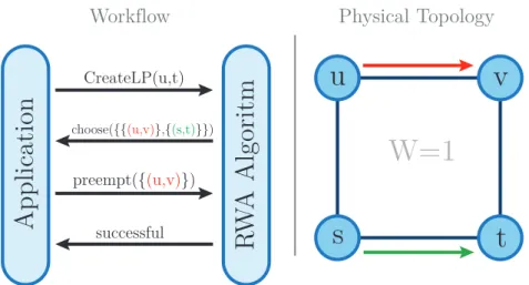
We present a preemptive routing and wavelength assignment algorithm for the online variant of the RWA problem which is able to use feedback from the applica-tion layer for making preempapplica-tion decisions. The work flow of our proposed RWA algorithm is depicted in Figure 3.1. Upon a lightpath request (that is made by an application) that cannot be fulfilled, our algorithm computes multiple candidates for preemption to choose from. These candidates are then passed to the application to choose which of the candidates to preempt, if any. This way the requester can rate the candidates using application-layer knowledge and present the best candidate to the RWA algorithm which then executes the preemption and establishes the newly requested lightpath by using the freed resources. This serves as a powerful building block when constructing networks that automatically adapt to the logical topology of the applications running on top of it.
When our RWA algorithm is used in a scenario where multiple applications run concurrently on top of the WDM network, these applications compete for lightpaths. Depending on the desired behavior of the network, it might be necessary to restrict the preemption such that a specific application can only preempt lightpaths that this very application requested earlier. Otherwise it is possible that applications mutually preempt lightpath set up by other applications. As in the remainder of this thesis we concentrate on networks exclusively used by a single application, it was not necessary to build such an authorization scheme. However, by record keeping which lightpath was requested by which application, such a scheme can by integrated to thereduce()
function used in Algorithm 1.
We identified two exemplary showcases for the use of our findings: the first one is a distributed algorithm to solve the Virtual Topology Design (VTD) problem in an IP-over-WDM network. The algorithm is further explained in Chapter 4. The second showcase are modern wireless cellular networks like Long Term Evolution (LTE). LTE Advanced uses what is called Coordinated Multi-Point (CoMP) transmission/recep-tion. In CoMP one User Equipment (UE) is jointly served by multiple basestations in bad connectivity scenarios. For a set of basestations to use CoMP, a certain data
3.2. Related Work
Application
RW
A Algorit
m
CreateLP(u,t) choose({{(u,v)},{(s,t)}}) preempt({(u,v)}) successfulu
v
s
t
W=1
Workflow Physical Topology
Figure 3.1.: Workflow of our proposed RWA algorithm. The right-hand side depicts the physical topology and established lightpaths.
rate between these nodes is required, where the data rate depends on a) the number of jointly served UEs and b) the quality of the wireless channel [DBKK12] between the basestations and UEs. Depending on these parameters, basestations query for new lightpaths in the backhaul network (a backhaul network is a wired network in-terconnecting basestations). The problem of selecting a proper preemption candidate in this scenario is a fairness problem which canonly be solved with measurements of the wireless channel between basestations and UEs.
The rest of the chapter is structured as follows: Section 3.2 discusses related work in both RWA algorithms and lightpath rerouting algorithms. Section 3.3 presents assumptions and definitions along with the graph model that is used. Section 3.4 describes our preemptive RWA algorithm, which is evaluated by simulation in Sec-tion 3.5. SecSec-tion 3.6 presents a conclusion.
3.2. Related Work
Existing routing and wavelength assignment algorithms can be differentiated by a) their assumption on the existence of wavelength converters in the network, b) their required knowledge about future lightpath requests, and c) their optimization criteria. In addition, they can be classified into algorithms which—given a new lightpath request—build new networks from scratch and algorithms trying to integrate the new lightpaths on-the-fly into the existing lightpath topology.
We are interested in preemptive RWA algorithms taking heterogeneous wavelength converters into account and handling new lightpath requests by on-the-fly network reconfiguration without knowledge about future lightpath requests. In addition to a low blocking probability, we are interested in a generic algorithm which is able to create lightpath topologies that comply with arbitrary custom constraints.
preemp-tion candidates exist in the literature. In the following, we will give an overview over some of these algorithms.
In [GM02] a simple lightpath reconfiguration algorithm for IP over WDM networks is presented. The algorithm adapts the lightpath topology of a WDM network to the observed IP traffic. Each lightpath is assigned two so called watermarks: WL and
WH. Whenever IP traffic on a lightpath is less than WL this lightpath is considered
as underutilized and therefore the lightpath is preempted. Analogously, whenever IP traffic on a lightpath is higher than theWH watermark, a new lightpath is inserted into
the network. Even though this algorithm uses preemption for network reconfiguration it is not possible to create lightpath topologies fulfilling any predefined constraints.
Ref. [XSBM08] studies the problem of service level agreement (SLA) violations in a WDM network under dynamic connection requests. SLAs specify a period in which a lightpath between two points in the network has to be active along with a availability requirement stating the amount of time the lightpath is allowed to be unavailable during that period.
A preemptive multi-class routing scheme with backup lightpaths is proposed in [WLYX07]. Lightpaths are assigned to different priority classes. Each Lightpath gets assigned a backup lightpath, which consists of a path through the network and a wavelength for each of the edges on the path that is not used by any other lightpath. In contrast to primary lightpaths, backup lightpaths are only planned but not active in the network. In case a primary lightpaths fails, for example due to a node or a fiber failure, the corresponding backup lightpath is created and takes over by handling all traffic previously carried by the failed lightpath.
In [XAG12] a routing and wavelength assignment algorithm for advance reservation of lightpaths is presented. The authors distinguish between lightpaths that are sched-uled for future inclusion and lightpaths that are active. The difference between those two types of lightpaths is that scheduled lightpaths only reserve network resources while active lightpaths occupy resources. If, for a new lightpath request, there are not enough free resources left (where a resource is free when it is neither reserved nor occupied) the algorithm tries to rearrange the scheduled lightpaths to free enough resources for the requested lightpath. If this fails, the request is denied.
When building a lightpath topology incrementally, the available network resources undergo fragmentation. One method to deal with fragmentation is rerouting existing lightpaths in case a new lightpath request cannot be handled. Several lightpath rerouting algorithms exist, i.e. [XAG12, LL96, CByL07, CL05, YR04], assuming either the wavelength continuity constraint or exploiting wavelength conversions.
In [LL96] the “parallel move-to-vacant wavelength retuning” (MTV-WR) algorithm is proposed. MTV-WR is an RWA algorithm that does not exploit wavelength conver-sion. Upon arrival of a new lightpath request between two nodes uand v, MTV-WR first tries to find a route for the new lightpath on a free wavelength. If this is not possible the algorithm checks if it is possible to retune existing lightpaths to other
3.3. Generic Graph model
wavelengths such that a route betweenuandv on a continuous wavelength is free. In [CByL07], MTV-WR is extended to MTV-OPA (move-to-vacant one-path-adjusting) for use in networks exploiting wavelength conversion. In addition to altering the wavelength of lightpaths, MTV-OPA is able to reroute existing lightpaths to different paths through the network. Unfortunately, the number of different rerouting candi-dates per request is bounded by one. Thus, many possible rerouting candicandi-dates are ignored, lowering the chances of successful rerouting.
Ref. [YR04] investigates rerouting based on calculatingkshortest paths. Simulation results show that under light load rerouting based on the k shortest paths lowers the blocking probability significantly. But with increasing load the success rate of the presented rerouting algorithm decreases massively.
3.3. Generic Graph model
3.3.1. Assumptions and Definitions
We assume a system in which the user of the network has the possibility to actively tell the network operator to increase the possible data rate between two points in the network by creating a new lightpath. We call this a request. Every request has a (possibly unlimited) lifetime determining how long the corresponding lightpath has to be active. After a lightpath exceeds its lifetime or upon a release request, it is removed and its associated resources are freed for future use.
As introduced in Section 2.1.1, the physical topology of the optical network is given by an undirected graph GP = (VP, EP) where VP are the nodes and EP the fibers
connecting those nodes. We assume each fiber can carry a total of W independent wavelengths, denoted by Λ ={λ1, ...λW}, W ∈N, which are used for data transmis-sion. Each of these wavelengths can be used for transmitting at a fixed data rate S.
A lightpath l = {(e1, ..., em),(λ1, ..., λm)}, ei ∈ EP, λi ∈ Λ, consists of a path
through the network and a wavelength for each edge on this path. We do not require the lightpath to use the same wavelength on each edge; hence, conversion from one wavelength to another is possible.
3.3.2. Graph Construction
This section presents a variation of the layered graph model [SBCL01, ZPC+08]. The basic idea of the layered graph is that each of theW available wavelengths can be seen as an independent layer. This idea is visualized in Figure 3.2 and the construction is discussed in the following.
We construct the layered graphGL= (VL, EL)of a physical topologyGP as follows:
As GL consists of W different layers, for each node v ∈ GP the nodes v1, ..., vW and
˜
u
srcv
dest . . . . . .Figure 3.2.: Layered graph with W wavelengths. Wavelength edges dashed. In this examplev is able to pass-through λi and to convert from λ1 to λ2.
2W edges are added to GL as follows: For each undirected edge (u, v) ∈ EP, add
the directed edges (˜ui, vi) and (˜vi, ui) to EL for 1 ≤ i ≤ W. In addition, for each
node v ∈ VP, add the nodes vdest and vsrc to VL which are used to interconnect the
different layers. These nodes are connected to the layers as follows: For eachv ∈VP,
add (vsrc, vi)and (˜vi, vdest)to EL, 1≤i≤W.
We will now add the wavelength conversion capabilities of each node to VL: If a
nodev is capable of converting an incoming signal on wavelength λi toλj, the edge
(vi,˜vj) is added to EL. We call such an edge a wavelength edge. Note that edges
betweenu˜i andvj (∀i, j ∈ {1,2, .., W}) represent physical fibers, while edges between
ui and v˜i (∀i, j ∈ {1,2, .., W}) represent wavelength conversion capabilities.
This graph construction implies full LS capabilities and hence does not support ROADMs with limited splitting hardware. But as ROADMs with limited light-splitting support are built from multiple smaller interconnected ROADMs (which have full LS capabilities), the limitation can be modeled by replacing the limited ROADMs inGP with its constituting parts.
3.4. Routing and wavelength assignment
Our RWA algorithm consists of four main parts: a) a greedy lightpath selection, b) a method to find conflicts with already established lightpaths in case the greedy strategy could not find a solution, c) a rerouting algorithm trying to reroute conflicting lightpaths to free resources for future usage, and d) a periodic cleanup module used to keep fragmentation low.
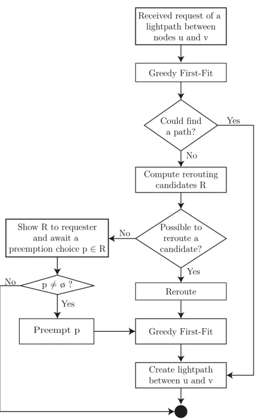
These parts are composed to constitute our algorithm as depicted by the flowchart shown in Figure 3.3. The flowchart is now described briefly; in the following, each building block is described in more detail. Upon a request for a lightpath between nodesuandv, at first the greedy first-fit algorithm is applied. If this algorithm could
3.4. Routing and wavelength assignment
not find a free path, multiple sets of conflicting lightpathsRare computed. Such a set c∈R is defined such that after removing all lightpaths in it, it is possible to create the requested new lightpath. Now it is checked if one of these sets can be rerouted such that a new lightpath betweenutovcan be established. If yes,R is passed to the requester of the new lightpath who can use its application-layer knowledge to choose whichc∈Ris to be preempted, if any. Afterwards, the new lightpath betweenuand v can be constructed over a path and with a wavelength assignment computable by the greedy first-fit algorithm.
3.4.1. First-Fit: Greedy shortest path routing
When considering a scenario with dynamic request patterns where new requests are submitted and old requests expire, it is important that new requests can be handled by the system. As there is no information in advance about newly arriving requests, it seems prudent to grant a request using as few resources as possible, maximizing the free resources of the network.
One possibility to use minimal resources to create a lightpath is to use a shortest path between source and destination [RSS09]. This path can easily be found by applying a breadth-first search on the layered graph. As no two lighpaths must share the same wavelength on any edge, all edges of the layered graph have to be removed which are already in use by a lightpath. As pointed out in [SBCL01], it is even better to use the least loaded path between two points in the network, where the load of an edge is defined in terms of lightpaths traveling through the corresponding physical fiber. To find the least loaded path in the network, a weighted shortest path algorithm such as Dijkstra’s can be used.
Depending on the desired behavior of the RWA algorithm, the greedy shortest path routing component either computes a shortest path on the layered graph using a breadth-first search or a least loaded path by using Dijkstra’s algorithm.
3.4.2. Lightpath preemption
Establishing lightpaths between two points based on the greedy algorithm works as long as there are enough free resources available. But as more and more lightpaths are established the number of free paths in the graph decreases and at some point there is a request that cannot be handled. This section presents a method to find multiple sets of already established lightpaths such that the preemption of all lightpaths in
any one of these sets allows the new request to be handled. In a subsequent step these sets can be analyzed to find the most feasible candidate for preemption. This can even be done in an interactive manner: Upon a new lightpath request that cannot be handled by the network, the RWA algorithm calculates multiple sets of preemption candidates. These sets are passed to the requester (which can be another program or even a human being) who is now able to analyze each candidate set. If all lightpaths
Greedy First-Fit Could find a path? Compute rerouting candidates R Possible to reroute a candidate? Reroute Create lightpath between u and v No Yes Show R to requester and await a preemption choice p ∈ R Preempt p No Yes p ≠ ø ? Yes No Greedy First-Fit Received request of a lightpath between nodes u and v
Figure 3.3.: Flowchart of the lightpath provisioning part of the proposed RWA algorithm.
3.4. Routing and wavelength assignment
u
t
s
l
1v
l
2(a) Simple graph with two established lightpaths l1 and l2 and W = 2 wave-lengths.
u
t
s
{l1} {l2}v
{l1,l2} 0 0(b) The corresponding conflict graph for lightpathsl1andl2.
Figure 3.4.: Construction of the conflict graph GC from a lightpath configuration.
in one of the sets are