Universidad Pública de Navarra
Escuela Técnica Superior de Ingenieros Industriales y de
Telecomunicación
Securing communications in
Surgery Robots
Grado en Ingeniería
en Tecnologías de Telecomunicación
Trabajo Fin de Grado
Beatriz V. Fernández Muro
Paolo Ernesto Prinetto
(Politecnico di Torino)
Giuseppe Airò Farulla
(Politecnico di Torino)
Acknowledgments
Completing a thesis is one of the most importants works in the profes-sional career, and I would not have been able to complete this without the aid and support of countless people over the past recent months.
First and foremost, I would like to thank my advisers from my destiny university Politenico di Torino, Prof. Paolo Prinetto and from my home university, Luis Javier Serrano Arriezu for the oportunity of working in a topic that I am really interested in, for their support and their always gen-erously feedback during all stages of the development of this thesis.
I am very much indebted to my adviser Giuseppe Air`o Farulla of the DAUIN Department at Politecnico di Torino. He consistently allowed this paper to be my own work, but steered me in the right direction whenever he thought I needed it, providing me advices, help and fast feedback whenever I ran into a trouble spot or had a question about my research or writing. Giuseppe also provided me contact with other students and the Cyber-Security group who I am also thankful to because of their help, advices and for calming me down in my first days and steps.
Moreover, I would like to thank my friends, family and relatives from Spain, Bulgaria, Portugal, Italy, Hungary and France, all of whom cannot be listed here, for accompanying me on this unforgettable experience. In particular I would like to mention Veni, Leonor, Rodrigo and Abel for their warm friendship, patient and for cheering me in my worst moments.
I want to express my gratitude to my best friend, Leire, who has helped me, advised me and motivate me even with almost a thousand kilometers of distance between us.
I dedicate this thesis to my beloved parents and my sister, Pedro ´Angel, Ma Pilar and ´Angela, whose love, company, efforts and understanding are
incomparable. They are my role models of honesty, strength, and persis-tence.
Abstract
This thesis describes the analysis and implementation of methods for ap-plying cyber-security to the exchange messages between tele-surgery robots. Several scenarios are developed while different security aspects to the com-munication between the nodes of Robot Operating System (ROS) are added. Those features concern the integration of Virtual Private Networks and de-vices specially tailored to cyber-security applications in a virtual scenario which represents a real one, applying the proper configuration on them in order to stablish encryption and authentication to the message exchange between the different robots.
The final goal of this analysis is to provide a solution to the cyber-security shortage in tele-surgery systems since its lack implies that someone’s life could be affected.
Keywords
Resumen
En el presente Trabajo Fin de Grado se estudia el an´alisis e imple-mentaci´on de m´etodos para aportar ciber-seguridad al intercambio de men-sajes entre robots de tele-cirug´ıa.
A lo largo del trabajo se desarrollan varios escenarios en los que se van a˜nadiendo distintos aspectos de seguridad a la comunicaci´on entre nodos de Sistema Operativo Rob´otico (ROS). Estos aspectos versan sobre la in-tegraci´on de Redes Privadas Virtuales (VPN) y dispositivos especialmente dise˜nados para aplicar ciber-seguridad en un escenario virtual representa-tivo del real, configur´adolos para establecer encriptaci´on y autenticaci´on en el intercambio de mensajes entre los distintos robots.
Con este an´alisis se pretende aportar un avance en el ´ambito de la tele-cirug´ıa ya que la seguridad tiene una alta relevancia, sin ella la vida de una persona puede verse afectada.
Palabras clave
Contents
1 Introduction 1 1.1 Motivation . . . 1 1.2 Objectives . . . 1 1.3 Structure . . . 2 2 State of art 3 2.1 Brief history of Robotics in medicin . . . 32.2 Resources . . . 7
2.2.1 Robot Operating System . . . 7
2.2.1.1 ROS communication . . . 9
2.2.1.2 ROS vulnerabilities and possible attacks on tele-surgery robots . . . 9
2.2.2 SEcubeTM . . . 13
2.2.2.1 SEKeyTM . . . . 16
2.2.2.2 SEFileTM . . . . 16
2.2.2.3 SELinkTM . . . 17
2.2.3 Tunnelling - Virtual Private Network (VPN) . . . 18
2.2.3.1 VPN Protocols . . . 19
3 Architecture and methodology 23 3.1 Material and methods . . . 23
3.2 Scenarios . . . 25
4 Results and discussion 34 4.1 Basic scenario . . . 34
4.2 Adding VPN to Basic scenario . . . 36
4.3 Adding SEcube to Basic scenario within VPN . . . 38
5 Conclusions 45 6 Future work 46 Appendices 47 A Table of surgical procedures per year 47 B Defence scenario 47 B.1 Basic scenario . . . 47
B.1.1 Publisher file in surgeon . . . 47
B.1.2 Publisher and Subscriber file in master . . . 50
B.1.3 Subscriber file in patient . . . 51
B.1.4 Configuration of the network and ROS parameters . . . 53
B.2 Adding the VPN . . . 54
B.3 Adding the SEcubeTM. Open/Close de DevKit device every time a mes-sage is sent/received. . . 55
B.3.2 Publisher and Subscriber file in Master . . . 62
B.3.3 Subscriber file in patient . . . 64
B.4 Adding the SEcubeTM. Open/Close de DevKit device only once. . . 71
B.4.1 Publisher file in surgeon . . . 71
B.4.2 Publisher and Subscriber file in Master . . . 76
List of Figures
1 PUMA 560: robotic surgical arm [1]. . . 3
2 Zeus Robotic Surgical System. . . 4
3 Da Vinci Surgical System. . . 4
4 Parts of the Da Vinci surgery robot [2]. . . 5
5 Number of world-wide procedures performed with da Vinci Surgical Robot System per year. Table with the exact values is available in A [3–5]. . . . 6
6 Effects of lag time on remote tele-surgery [6]. . . 7
7 ROS basic features schema: relation between nodes, topics and services [7]. 8 8 Schema of network when a Man In The Middle attack is being carried out. 10 9 Schema of steps that an attacker has to follow in order to know the relevant information of the ROS network to execute an attack. . . 12
10 SEcubeTM components. . . . . 14
11 The SEcubeTM Dev Kit Board. . . . 15
12 SEcubeTM Dev Kit Board: interfaces and peripherals. . . 15
13 The USEcubeTM Stick. . . . 15
14 USEcube Internal structural details. . . 15
15 SEcubeTM: Software architecture. . . 16
16 SEfile: process of coding the name of the file. . . 17
17 SELink: Client and Server side components [8]. . . 17
18 SELink: Connection establishment process. . . 18
19 SELink: final connections. . . 18
20 VPN definition summary. . . 19
21 Secure Architecture of a ROS Network using SEcubeTM. . . 23
22 Secure Architecture of a Surgery Robot Network using SEcubeTM . . . . 24
23 ROS: schema of publishers, subscribers and topics in a Surgery Robot network. . . 25
24 Basic scenario: schema of virtual machines. . . 25
25 Basic scenario: axes of movement when surgeon moves the robot. . . 26
26 Scenario 1: networks and schema of folders and files in each virtual machine. 27 27 VPN: schema of virtual machines. . . 28
28 VPN: network. . . 28
29 Encryption and decryption process using SEfile library. . . 30
30 Encryption and Decryption algorithm processes. It is represented each mode of encryption/decryption (CTR or ECB) depending on the block. . 31
31 Schema of variables and environment needed in Surgeon node to encrypt the data sent via ROS within VPN. . . 32
32 Schema of variables and environment needed in Patient node to decrypt the data received via ROS within VPN. . . 32
33 Plain data of a message sent via ROS. . . 35
34 Basic scenario: Wireshark capture of a plain message when surgeon prints its data. . . 36
35 Basic scenario: Wireshark capture of a plain message when surgeon send the motion data. . . 36
36 Adding VPN scenario: Wireshark capture of messages in master Virtual
Machine. . . 37
37 Adding VPN scenario: Wireshark capture of messages in external PC. . . 38
38 Encrypted data of file created using SEfile library. . . 39
39 Encrypted data of a message sent via ROS. . . 39
40 Encryption process of 4 messages in terminal . . . 40
41 Decryption process of 4 messages in terminal . . . 41
42 Encryption process of a message in terminal and the encrypted content that is sent. . . 41
43 Time-lag graphs of encryption and decryption processes using and not using SEcube. . . 43
44 Time-lag graphs of encryption and decryption processes using SEcube. Comparison between the process of opening and closing the device only once or every time a message is exchanged. . . 44
List of Tables
1 Comparation between VPN protocols [9]. . . 22 2 Example of encode commands. . . 26 3 Number of Surgical Procedures per year from 2011 to 2018. . . 47
1
Introduction
The topic of this thesis is related to secure tele-surgery, surgical procedures carried out remotely thanks to advances in robotic and computer technology.
This thesis focuses on ROS (Robotic Operating System) [10] architecture, security and applications given it is the most preferred software architecture of robotic applications, including surgical ones such as Raven II [11] or da Vinci Reseach Kit [12] robots.
1.1
Motivation
There is a wide range of medical robotics applications such as Robotic Assistance, Surgi-cal robots, Pharmabotics, Companion Robots, Disinfectant Robots in healthcare, etc, [13] and applications related to them are increasing nowadays. Their use is expected to be very common in the future which signifies robots’ architecture and communications have to be secure by reason of, as main goal, the patient who is being operated could not be harm by any external agent.
The analysis and research on tele-surgery - which implies ROS as well - remain in con-tinuous improvement and, being focused on terms of security, it is well known that ROS developers did not focus on the cyber security of the system, quoting Brian Gerkey at the ROS-I conference in Stuttgart: “If you claim that you’ve found a security hole in ROS, you’re lying: there is no security”. Securing ROS is important in tele-medicin applications such as surgery robots, due to the possibility of suffering an attack which could damage the robot and even harm people as the surgeon or the patient.
1.2
Objectives
The principal purpose of this thesis is to provide security to the whole communication channel and the messages exchanged between robots, particularly in the area of Tele-surgery.
The first objective is to create a simple scenario that represents a tele-surgery network, designing and developing it using a virtualized environment. The second one is to imple-ment strategies of how to secure the environimple-ment after having a deep study and analysis
of them.
1.3
Structure
This thesis is organized as follows:
Section 2 introduces the state of art of Tele-medicin and provides a description of the history of surgery robots with a focus on possible attacks and countermeasures. Section 3 describes the methodology that has been used as well as the scenarios devel-oped, showing the vulnerabilities of each one and implementing security improvements until a final - secure - scenario.
Section 4 and Section 5 give the results achieved and some conclusions derived from them.
Section 6 presents the ideas of future work on this topic and possible improvements. All the code developed for this thesis is presented and explained in the Appendices at the end of the thesis.
2
State of art
2.1
Brief history of Robotics in medicin
Since the XX century, robotics has been applied to different fields, not only to the in-dustry field but also to research. Ideas of its use in medicin did not take long to appear, PUMA - Programmable Universal Machine for Assembly, or Programmable Universal
Manipulation Arm - was created by Victor Scheinman as an industrial robotic arm but PUMA 560, Figure 1, was used for the first time in robotic stereotactic brain biopsy in 1985. Three years later, PROBOT was used to perform transurethral prostate surgery and in 1992, ROBODOC was used to prepare (more precisely and quickly than the human surgeon) a cavity in the femur for hip replacement in human patients.
Figure 1: PUMA 560: robotic surgical arm [1].
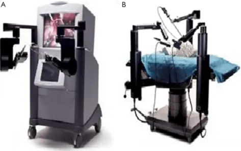
In the decade of 1990 the da Vinci Surgical System and Zeus Robotic Surgical systems (Figure 2) were designed for minimally invasive surgery. Many surgeries were carried out by the Zeus system that time but finally the da Vinci Surgical System (Figure 3) became the most used and most known for its use in general surgery, urology and gynaecology [14].
Figure 2: Zeus Robotic Surgical System. (A) Surgeon console (B) Robotic arms. [1]
Figure 3: Da Vinci Surgical System.
From left to right: surgeon console, patient cart, vision cart. [1]
Da Vinci system is based on a “Master-Slave” paradigm. The surgeon uses a console which controls the arms using joysticks and foot pedals as Figure 4 shows. These joysticks copy the movement of the hands, scaling it and applying a filter of possible tremors. This console also contains a 3-Dimensional screen allowing the surgeon to see the surgery without needing special glasses. [2]
Figure 4: Parts of the Da Vinci surgery robot [2].
Some significant advantages of using the Da Vinci system are its 7 Degree of Freedom (DoF) and that a surgeon controls the surgery from a seated position separated from the patient. This method is known as telesurgery and can theoretically be performed from any distance. 7 DoF, which means 7 independent parameters that define the movement, are typically required to mimic the movement of human forelimb.
Figure 5 represents the number of operations using da Vinci surgical robot system from 2011 to 2018. It can clearly be seen that there has been a significant increase in the amount of them. Approximately 350,000 surgical procedures were performed in 2011, 753,000 and 877,000 procedures were performed in 2016 and 2017 respectively, and they are expected to increase around 11% to 15% in 2018 [3].
Figure 5: Number of world-wide procedures performed with da Vinci Surgical Robot System per year. Table with the exact values is available in A [3–5].
Owing to the rising trend in Figure 5, it could be claimed that the demand for op-erations is growing really fast, which implies that improvement on the methodology has to be developed. Some experts believe that the next step in tele-surgery progress will be the combination of surgical robotics and artificial intelligence.
There is also a problem with da Vinci Surgical System: the machine is very expensive, it is not portable and it uses a proprietary software as well. However, it has been developed an affordable and Linux-based operating system that lets users modify code, which is called Raven II. The mentioned system consists of two robot arms, a camera, and an interface for the surgeon.
In tele-surgery the lag time is really important and many researchers have studied about the possible impact of its smaller or bigger value. In [6] and [15] it is explained that surgeons can adapt to tele-surgical latencies but the maximum latency recommended is about 300ms. Figure 6 shows the effects of the delay depending of which is the value of the time-lag.
Figure 6: Effects of lag time on remote tele-surgery [6].
This values refers to possible problems caused by video lacency which could make the surgeon to be confused and to not make his/her best.
2.2
Resources
Owing to the increasing use of this method in surgeries it has become necessary to secure the systems, which means to secure ROS. To know how to secure the system, what Robot Operating System is, its vulnerabilities and some possible hardware and software to develop security have been investigated.
2.2.1 Robot Operating System
As defined in ROS Wiki [7] “ROS is an open-source, meta-operating system for your robot. It provides the services you would expect from an operating system, including hard-ware abstraction, low-level device control, implementation of commonly-used functional-ity, message-passing between processes, and package management. (...) The primary goal of ROS is to support code reuse in robotics research and development”.
The ROS framework is implemented in different programming languages such as C++, Python and Lisp and research is being carried out in order to implement JAVA and Lua. In terms of operating systems in which ROS could be used, it only runs on Unix-based
platforms; although a port to Microsoft Windows is possible, it has not been tested yet. The network of ROS isComputation Graph, a peer-to-peer network of processes that are processing data together [7]. The basic Computation Graph concepts of ROS are:
· nodes: written with the use of a ROS client library, such as roscpp or rospy. The communication with one another uses streaming topics, Remote Prodecure Call services, and the Parameter Server.
· master: provides name registration and lookup to the rest of the Computation Graph, without it, nodes would not be able to find each other, exchange messages, or invoke services.
· parameter server: allows data to be stored.
· messages: a data structure, comprising typed fields. Messages are routed via a transport system with publish/subscribe semantics: a node sends out a message by publishing it to a given topic.
· topics: an identifier of message’s content.
· services: provide request-reply interactions between nodes.
· bags: files format for restoring ROS message data.
As a summary of what is mentioned above, Figure 7 shows a diagram of how the structure of a pair of nodes which are communication in a topic is.
2.2.1.1 ROS communication
Information about the availability of topics, services and the negotiation of connection transport are implemented using XML Remote Procedure Call (XML-RPC). It is the backend of the ROS system APIS which provides the communication between the nodes [16]. There are three different API listings, Master API, Parameter Server API and Slave API that are available in [17], [18] and [19]. Some of the most relevant functions for our study are:
· getSystemState - Master API: shows a list representation of system state, for example publishers, subscribers, and services.
· lookupNode - Master API: provides the XML-RPC URI of the node with the as-sociated name, or caller identifier, called within the function. This API is used for looking information about publishers and subscribers.
· publisherUpdate - Slave API: after a node is subscribed to a specific topic, this functions will also provide information about new publishers in that topic.
2.2.1.2 ROS vulnerabilities and possible attacks on tele-surgery robots
The system has known vulnerabilities due to the fact that the security in ROS was not taken into account:
1. the messages which are sent between ROS core and a node are non-encrypted 2. no authentication is required
3. there is no confidentiality
The lack of encryption, confidentiality and authentication lets an attacker carry out unau-thorized Publishing (Injections), unauunau-thorized Data Access, and even Denial of Service (DoS) attacks on specific ROS nodes [20] :
• Unauthorized publishing: a node is able to publish data to an arbitrary topic without prior authorization, what makes it possible to inject data or commands into an application in order to disturb its operation and even false sensor data.
• Unauthorized data access: every node in ROS may subscribe to every topic within the application. After that, it will receive any data that is published for this topic. This attack is especially hard to discover since a node itself may have no outgoing ROS communication.
• Denial of Service: there is no control of which node should publish any partic-ular data, which makes it easy to launch an attack that publishes a large number of fake data. The attacker can also prevent the subscriber from receiving the real data.
It is possible for an attacker to deal with unauthorized publishing and unauthorized data access attacks at the same time, for instance, a malicious node may act as a subscriber to a publisher and as a publisher to a subscriber - a Man In The Middle Attack - and transparently record and manipulate the data flow between those two nodes, represented in Figure 8 as a change of the data exchange - 0 is modified to 1. In this situation, the attacker is receiving data from the topic (receives data=0) which means unauthorized data access and, after that, he is publishing the data on a topic that he has no authorization, unauthorized publishing.
Figure 8: Schema of network when a Man In The Middle attack is being carried out. The attacker acts as publisher or subscriber depending on what node is it attacking.
Authors in [21] classify attackers to medical robotic infrastructures into two groups, considering the attacker’s role within the system:
robot. Based on the collected information he/she starts inserting false messages into the network, while still allowing both the benign parties to communicate directly. (II) Network intermediary that assumes a role of an intermediary between a robot and a
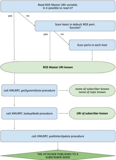
surgeon, such as MITM (Figure 8). The benign parties don’t communicate directly. Figure 9 represents a schema of the process to develop an attack and know the rele-vant information of the ROS network, such as topic names and addresses of the nodes. Typically, the first step is to find the URI of the ROS master - which is the IP and port of the ROS master. There are different possibilities to do so, the first one is to read it from the ROS MASTER URI environment variable - the one that client nodes use to locate the master node - but even if that is not possible, yet an attacker can scan the network using Address Resolution Protocol (ARP) in order to identify the hosts in the network. Once the hosts are known, the master can be found by trying the ROS default port on each host until it is found. If the master is configured to use a different network port - with respect to the default ROS port 11311 -, a full portscan on all nodes must be performed.
Next requirement is to get the URI of the subscriber. To do so, first a call to the proce-dure getSystemState within the XML Remote Proceproce-dure Call, previously introduced in section 2.2.1.1, is carried out. The master will return information about the registered publishers, subscribers and services so the node name and topic name is known.
Now, after extracting the name of the subscriber which should receive the (faked) mes-sages, the URI of the subscriber could be got by sending a lookupNode XMLRPC message to the master with the name of the node as parameter. With this URI, the attacker is able to send the XMLRPC message publisherUpdate to the subscriber, containing the topic and a list of the new publishers to the topic - which contains the (fake) publisher created by the attacker.
While the original publisher is still active and visible in the ROS graph, its data will not reach the subscriber anymore. Note that this attack is reversible, thus, after being done, the attacker can just send another publisherUpdate containing the original pub-lishers [20].
Figure 9: Schema of steps that an attacker has to follow in order to know the relevant information of the ROS network to execute an attack.
According to the impact of the attack on the surgery, it is also possible to distinguish three different categories [21]:
(A) Intention modification: the attacker modify the messages while packets are in-flight, the surgeon has no control over them. The effects of this attack could be for example:
· robot becoming randomly engaged or disengaged
· unusual delays in movements
Considering the attacker’s role as a network intermediary, it could be diferentiated four subgroups of attacks:
(a) Reordering → the attacker does not forward the messages to the robot in the same order as he/she receives it, the attacker sends them in a random order (and with some delay) what produces that the robot skip the messages received out of order, playing out a jerky robot motion.
(b) Packet loss→the attacker drop some packets which makes the motion become delayed and jerky.
(c) Packet delay → the attacker does not forward the messages in the exact mo-ment he/she receives them, but sends them after some amount of time. (d) Content modification → the attacker modifies surgeon’s packets on-the-fly
before forwarding them to the robot.
(B) Intention manipulation: the attacker only modifies feedback messages originat-ing from a robot, such as video feed or haptic feedback. As the feedback is assumed to be valid, the attack could end up becoming harmful to a patient.
(C) Hijacking attacks: the robot ignores the intentions of a surgeon completely, and, instead, performs some potentially harmful actions. These attacks cause a temporary or a permanent takeover of the robot.
2.2.2 SEcubeTM
The exploits explained in the previous section occurs for any robotic system with tele-communication. Taking Brian Gerkey’s quote in the ROS-I conference in Stuttgart“ROS assumes a secure network! If that assumption is not true, arbitrarily bad things can hap-pen” into consideration, it could be assumed that the only way to secure the system is securing the network where the system is developed.
The first strategy is to provide security to the whole communication channel between all the parts of a system, providing a layer of security. By adding encryption and authenti-cation to data streams - although the use of them will increase the use of memory, the amount will be acceptable in most cases [21] -, the attacker will have to carry out more complex attacks because it will become hampered.
Blu5 Group 1 develops added value “bricks” for others to build integrated trusted systems. An example of interest in the topic of our concern is SEcubeTM that, in rough
lines, provides:
- secure key storage,
- encryption and decryption of data stream - authentication of data streams
SEcubeTM- Secure Environment cube - Open Security platform is an open hardware and
software platform for security and application developments, a system on Chip embed-ded environment, a unique security environment where each function can be optimised, executed, and verified on its proper hardware device [8].
Three key security elements in a single package are implemented: a fast floating-point Cortex-M4 CPU, a high-performance FPGA, and an EAL5+ certified SmartCard as rep-resented in Figure 10.
Figure 10: SEcubeTMcomponents.
1
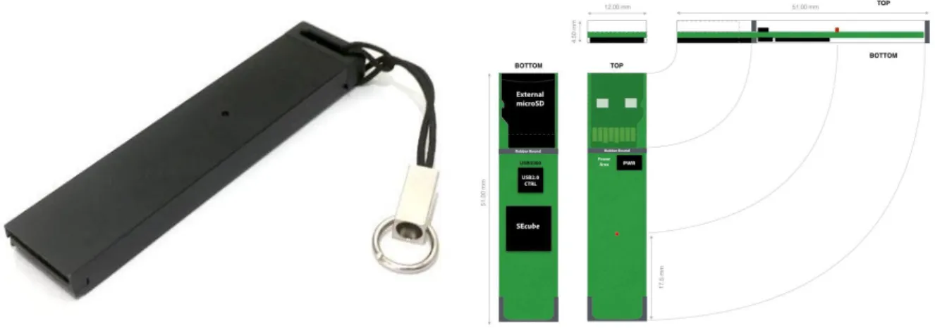
Besides the already described SEcubeTM Chip, there are two other hardware devices
related to SEcube: the Development Board, named SEcubeTM DevKit (represented in
Figures 11 and 12) and the USB Stick, named USEcubeTM Stick (represented in Figures
13 and 14). The SEcubeTMDevKit is an open development board designed to support
de-velopers to integrate theSEcubeTMChip in their hardware and software projects whereas
USEcubeTM Stick is an USB form factor based on the SEcubeTM Chip, which deploys
the SEcubeTM functionalities through a USB 2.0 High-Speed interface [22].
Figure 11: TheSEcubeTMDev Kit Board. Figure 12: SEcubeTMDev Kit Board: interfaces and peripherals.
Figure 13: TheUSEcubeTMStick.
Figure 14: USEcube Internal structural details.
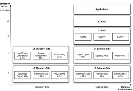
The architecture of the firmware - represented in Figure 15 - is based on Abstraction Layers (L0, L1, L2, L3 and Applications) in which each element (but the lowest one) represents a “service” for the upper level and relies on “services” provided by lower levels [8].
Figure 15: SEcubeTM: Software architecture.
What makes SEcubeTM interesting, in terms of security, is that developers are pro-vided with an easy-to-use, high-security abstraction layer - all the digital and organisa-tional security processes are integrated in a comprehensive, flexible and seamless way, for instance, mathematical and cryptographic elements, like keys and algorithms, are re-placed by simpler concepts: groups and policies -, but security experts can verify, change, or write from scratch the whole system starting from the elementary low-level blocks. The APIs are organised in modular libraries and abstraction layers and developers are open to create their solution starting from the most suitable entry point according to their expertise. The L2 level APIs offer optimized and easy-to-use functionalities to ease the development of applications fully protected (i.e., authenticated and confidential), without being forced to understand in details all the low-level hardware and security mechanisms. The provided APIs include:
· SEKeyTM : a Key Management System. Whenever a group - pool of one or many
users - is created, SEKeyTM manages the creation of the group communication key (which is used to generate session communication keys and a set of security policies), the security mechanisms and the relative transmission to the entitled users.
facilities, based on two master keys (EncDBKey and SigDBKey). Every secure file is encrypted and signed, sector by sector, using dedicated keys derived by the two mSE master keys, and - as represented in Figure 16 - the file name is coded in a way that nobody can recognize it looking directly at the physical file system.
Figure 16: SEfile: process of coding the name of the file.
· SELinkTM: a data-at-motion protection facility. It secure the network traffic
by encrypting network streams originating from any application, regardless the application-level protocol. Encrypts connections silently with no modification to the application. Figure 17 shows the architecture, the Client-side components are SELink driver, SELink service and SELink GUI, and the server-side ones are
SELink gateway and SELink gateway web UI. Figure 18 represents how a driver redirects the connection requests toSELink service and, finally, Figure 19 shows the final connections where the Service and Gateway components take care of bridging non-secure connection to the Secure Link.
Figure 18: SELink: Connection establishment process. Each directed arrow represents a TCP connection request [8].
Figure 19: SELink: final connections. Each directed arrow represents a TCP connection [8].
2.2.3 Tunnelling - Virtual Private Network (VPN)
BesidesSEcubeTM, another technology used to carry out this purpose is Virtual Private
Network (or VPN), which is a technology built using public wires - usually the Internet - to privately connect remote users.
The advantage of using VPN is that connections between remote networks could be established no matter of the distance and that, as added value, it guarantees the security level when the underlying infrastructure cannot provide it on its own. It secures the private network, using encryption and other security mechanisms to ensure that only authorized users can access the network and that the data cannot be intercepted. This type of network is designed to provide a secure, encrypted tunnel in which transmit
the data between one user and another - remotely connected. This means that once a connection through a VPN is established, all the traffic becomes encrypted and - as shown in Figure 20 - the client’s IP address (IP X) gets replaced (in eyes of external agents) with the address (IP Y) of the VPN server - the third party that connects to the final destination on your behalf.
In rough lines, using a VPN provides:
· Encryption of the online data
· Activity hiding from any external agent
· Location hiding
· Anonymity
Figure 20: VPN definition summary.
Hosts on Internet will see the IP address Y as the IP address of the devices and an external agent could not be able to manage the online data.
There are different implementations of VPN such as IPSec, OpenSSH, OpenVPN, Socat, etc, and many differents protocols to use within them.
2.2.3.1 VPN Protocols
A VPN protocol defines how the service handles data transmission over a VPN. The most common protocols are all to be cited:
· Point-To-Point Tunneling Protocol (PPTP) was designed by Microsoft as part of the Windows Operation System. It encapsulate the existing protocol PPP
(Point-to-Point Protocol). Due to its easy configuration it is one of the most used protocols, but its autentication protocols, such as MS-CHAP-v1/v2, make it vulnerable.
· Layer 2 Tunneling Protocol (L2TP) is a combination of PPTP and Cisco’s L2F protocol and it is also associated with the Internet Protocol security (IPsec) pro-tocol in order to apply a strong encryption and authentication. It establishes a secure connection using keys for authenticating and encrypting each IP packet of the communication, nonetheless there may be ways for an attacker to decrypt the VPN session.
· Secure Socket Tunneling Protocol (SSTP) transports the traffic through Secure Sockets Layer (SSL) protocol and use SSL/TLS encryption.
· Internet Key Exchange Version 2 (IKEV2) establishes a security association over IPsec. IKE uses a Diffie-Hellman secret exchange of keys in order to establish the shared secret of the session.
· OpenVPN is a full-featured open source SSL VPN solution provided in the Ubuntu Repositories and licensed under the GNU General Public License (GPL). It imple-ments OSI layer 2 or 3 secure network extension using the SSL/TLS protocol. Table 1 represents a comparison between all this protocols. It is focused on their security and uses in order to know which one meets our requirements and specifications: to get the objective of this thesis the whole session has to be secured as much as possible so OpenVPN is used owing to its principal advantages such as portability, compatibility with NAT and dynamic addresses, ease of configuration and fast speeds, and because it is one of the most secure protocols, the most reliable and the most stable.
It accommodates a wide range of configurations, including remote access, site-to-site VPNs, Wi-Fi security, and enterprise-scale remote access solutions with load balancing, failover, and fine-grained access-controls [23].
OpenVPN is the best option for our purpose because it is open-source, its installation is easy and fast, it supports NATs and has cross-platform portability across most of the
known computing devices and, in addition, it has encryption combined with authentica-tion which could be useful for our security purpose.
Still it is not impenetrable by an expert attacker so we need to add extra security - by implementing SEcube - that does not conflict with the one offered by OpenVPN: by leveraging on both, we ensure compliance to best standards in security.
PPTP L2TP/IPsec SSTP IKEV2 Op enVPN Encryption Strength 128 bits using MPPE proto col 256 bits using AES cipher 256 bits 256 bits using AES cipher 256 bits using AES cipher Securit y Basic e n c ryption Highest encryption: chec k s data in tegrit y and encapsulates the data twic e Highest encryption: data gets v erified b e-fore b eing sen t and receiv ed, S SL en-cryption included F astest and most se-cure VPN proto col Highest encryp-tion: Authen ticates data with digital certificates Sp eed F ast due to lo w er lev el of encryption Relativ ely slo w, requires more C P U pro cessing Slo w sp eed due to sup erior lev el of pri-v acy and securit y F ast sp eeds F ast sp eeds Compatibilit y · Windo ws · MA C · iOS · Windo ws · MA C · iOS · Windo ws · MA C · Windo ws · MA C · iOS · Windo ws · MA C · iOS · Android · Lin ux · Router · Raspb erry Pi · Qnap · Synology Nas T able 1: Comparation b e tw ee n VPN proto cols [9].
3
Architecture and methodology
To create the proposal for this thesis, all the exposed and described specifications in State of Art section has been taken into account. By doing this, the implementations thought for securing a tele-surgery scenario are ensuring to be accurately conveyed.
The methodology adopted is based on creating a basic scenario with no security, and add security improvements - OpenVPN and SEcubeTM - to it until a secure scenario is developed.
3.1
Material and methods
The resulting architecture in Figure 21 shows the secure communication between a node and ROS core. ASEcubeTMis going to be used for each robot of the network and another
for the Master PC (in which ROS core is going to be run) as well.
In the particular case of Surgery Robots, as Figure 22 shows, it will be needed a first
SEcubeTMdevice - previously introduced in section 2.2.2- for the robot where the surgery is taken place, a second one for the robot which the surgeon will use and a third one for the Master PC.
However, in this thesis, it is going to be used only two SEcubeTM Development Kits
-one in Surgeon node and another in Patient node - instead of three as explained in the previous paragraph. This change in the scenario was applied due to a faster development and because it is not compulsory, nor necessary, that the Master node use it: the only purpose of the mentioned node is to resend the data from the Surgeon to the Patient and for that, it does not need to understand the exchanged data.
Robot ROS core ROS Network SEcube SEcube Non-secure communication Secure communication
The network has been thought to enable a tele-surgery, that is to say that is remotely-connected: the surgeon could be in a hospital from, for instance, Germany, and the surgery could take place in, for example, Italy. So, we use VPN to provide connectivity between remote networks no matter how far they are or if the Network Address Transla-tion (NAT) [24] configuraTransla-tion is set - which do not let the connecTransla-tion to be established.
Robot (Surgeon)
Master PC
(ROS core) SEcube
SEcube Robot (Pacient) SEcube Non-secure communication Secure communication
Figure 22: Secure Architecture of a Surgery Robot Network usingSEcubeTM
When the surgeon robot has to communicate with the patient robot, the path which the messages has to go through is:
Robot (surgeon) ←→ Master PC ←→ Robot (Patient)
It will never be possible to directly communicate between the surgeon robot and the patient robot: in terms of programming in ROS - as explained in section 2.2.1 -, there is a listener in the Master PC subscribed to a topic in which a publisher in the surgeon publishes; moreover, there is another listener in the patient robot which is subscribed to a second topic, in which the Master PC’s publisher publishes. A clarifying schema of the structure could be seen in Figure 23, in which the concepts related to a first topic are printed in a green color and the ones related to a second one are in blue.
Figure 23: ROS: schema of publishers, subscribers and topics in a Surgery Robot network.
3.2
Scenarios
To study the final scenario, in which a surgery robot will be implemented developing VPNs and using SEcubeTM, we have worked on different virtualized scenarios.
(I) Basic scenario:
Three nodes in different virtual machines are implemented - as represented in Figure 24 -, representing Master PC, surgeon’s robot and patient’s robot each, in which a communication protocol is used. This protocol is based in 4 types of messages that include different information:
0 = Emergency Stop 1 = Initialization 2 = Pedal UP 3 = Pedal DOWN
Figure 24: Basic scenario: schema of virtual machines.
In the case of Pedal DOWN, besides the code 3 it will be also sent the movement that the patient’s robot has to follow [25]. The movement could have different di-rections so, for simplicity and clarity, three axes are represented: X, Y and Z. Each
of it is shown in Figure 25: X represents right (positive) and left (negative), Y, up (positive) and down (negative) and Z, the depth: when the movement goes to the front it is negative and when it gets closer to the surgeon, positive.
As an example of what has just been explained, in Table 2 it is shown the encode data of some given instructions.
Figure 25: Basic scenario: axes of movement when surgeon moves the robot.
Instruction Encode result
Emergency Stop 0
Init 1
Pedal Up 2
Pedal Down and the movement that the surgeon does is 1 left, 2 up and 0.3 to the front
3 ->-1 2 -0.3
Pedal Down and the movement that the surgeon does is 0.2 right, 0.1 down and 0.1 to him
3 - >0.2 -0.1 0.1
Table 2: Example of encode commands.
A in-deep explanation and the code of this scenario could be found in Appendix B.1.
To create the scenarios it has been used 3 virtual machines where it has been implemented one node each - with its required ROS files - as Figure 26 shows. The
figure mentioned also represents the network of the scenario: Surgeon and Master machines are in one network and Master and Patient ones, in another, what means that surgeon has one interface in Internal Network mode, master has two in the same mode but different networks each and finally, patient, as surgeon machine, has only one.
Figure 26: Scenario 1: networks and schema of folders and files in each virtual machine.
Besides, owing to ROS configuration in multiple machines, a configuration of ROS parameters and default routes to concrete IP addresses have to be set. This config-uration and its steps is available in Appendix B.1.4.
(II) Adding the VPN to basic scenario:
Same structure as the first one but adding tunnels, using OpenVPN - introduced before in Chapter 2.2.3.1 -, in order to provide the connection though Internet between every remote network.
In this scenario, each virtual machine is connected to Internet through a bridged interface as shown in Figure 27. Moreover, the surgeon node and patient node are VPN clients and the master node is the VPN server. This architecture and the
tunnels that are going to be created are represented in Figure 28.
Figure 27: VPN: schema of virtual machines.
Figure 28: VPN: network.
A in-deep explanation of the architecture and configuration of this scenario could be found in Appendix B.2.
The verification of OpenVPN working properly for our objective has been done analyzing the exchanged messages. For this purpose Wireshark tool is utilized cap-turing a message exchange between master and surgeon. This results are available in section 4.2.
(III) Adding SEcubeTM to the basic scenario within VPN (complete scenario):
Same structure as the second mentioned, but SEcubeTM is added in each node to make the communication secure - encrypted and authenticated.
Given the fact that what is needed in the field of tele-surgery within ROS is to secure the exchanging information via ROS topic, there are many possibilities, it is possible to implement theSEFileTM libraries and SELinkTM ones as well to secure
the whole software environment where ROS runs.
Besides, installing the ROS core on top of a protected File System on UserSpace (FUSE) allows building a system that intrinsically prevents external agents (attack-ers) from tampering with any of the functionalities exposed by ROS. In addition, the attacks mentioned in section 2.2.1.2 will be hindered, neither an attacker could modify the core libraries used by ROS - the ROS environment -, nor could change any of the configuration files used by a robot to store its inner status and parameters.
In the current work, SEfile is going to be used: although this process is a data-at-rest protection - it creates a secure, signed and encrypted file with an encrypted name from an unsecured file which contains plain text -, it could be use in ROS systems by creating and reading files in each node:
1.- the content of the ROS message is created as a file in the publisher node. 2.- the data of the file is encrypted and wrote as the file content.
3.- the new encrypted data is read and sent through the communication channel. Consequently, the opposite process takes place in the subscriber node:
4.- the received data is saved as a file. 5.- the resulted file data is decrypted.
6.- That plain text generated data is read and execute by the patient node. The schema of the whole process is represented in Figure 29 with the intention of clarifying the concept.
Figure 29: Encryption and decryption process usingSEfile library.
The Encryption Algorithm used is The Advanced Encryption Standard (AES) [26] which is a symmetric cryptography algorithm that ciphers blocks of data. Nowa-days, some theoretical attacks have been shown, but still it has not been detected a successful attack to this cipher what makes of it a proper option to use. In SEfile, the data-to-encrypt is divided into blocks, and each block is encrypted separately: each sector is encrypted using AES-256-CTR with exception of the header that is encrypted using AES-256-ECB. This concept is represented in Figure 30.
The first mode, CTR - counter - generates the next keystream block by encrypt-ing successive values of a value called “counter” which is a sequence that is not repeated for a long time. That way, each block cipher depends on an ascending counter which start from a randomly selected initialization vector. Today, CTR mode is widely accepted and any problems are considered a weakness of the under-lying block cipher. The Electronic Codebook mode, instead, is used in the header to provide independence from any initialization vector.
(a) Encryption algorithm process of two blocks and the header.
(b) Decryption algorithm process of two blocks and the header.
Figure 30: Encryption and Decryption algorithm processes. It is represented each mode of encryption/decryption (CTR or ECB) depending on the block.
Data confidentiality is guaranteed with the algorithms mentioned above, but au-thentication is also required. To sign each sector, including the header, Secure Hash Algorithm (SHA) - in particular SHA-256 - and keyed-hash message authentication code (HMAC) are used what means that within SEfile the signature depends on both the data contained in the sector itself and on a chosen encryption key. For having a deep explanation of how this algorithms works within SEfile see the pdf file available in [22].
These processes of authentication and encryption are carried out creating a secure environment setting variables that are going to be used within the functions such as a session identifier, key identifier and cipher algorithm and mode.
The code and explanation of this scenario could be found in Appendix B.3.
Finally, Figure 31 and 32 summarize the in-variables needed in Publisher and Pa-tient node functions, respectively.
Figure 31: Schema of variables and environment needed in Surgeon node to encrypt the data sent via ROS within VPN.
Figure 32: Schema of variables and environment needed in Patient node to decrypt the data received via ROS within VPN.
Since the main goal of this thesis is applying the secure pipeline to tele-surgery, an application where even a small time-lag could cause huge problems, it is mandatory to analyse the performances of the proposed solution.
For this goal, we need to know how much time does the encryption and decryption processes take. To do so, the Boost library of C++ is going to be used and four different measures will be analysed: publisher and subscriber time-lags using SEcube and pub-lisher and subscriber time-lags not using SEcube. The values obtained with this process correspond to the difference of the time when the data is ready to be sent and the time when the motion data from the instructions file is read. A schema of the included pro-cesses when calculating the time-lag of encryption or decryption is shown in Equations 1, 2, 3 and 4. With this measure, the time-lag that distance or network use could cause is not interfering in the analysis.
time lag =time 1−time 0 time0 = read instructions
time1 =read instructions+encode data+write encoded f ile+encrypt+read encrypted f ile
Equation 1: Schema of which functions does the calculation of time-lag in publisher include whenSEfile is being used.
time lag =time 1−time 0 time0 = read instructions
time1 = read instructions+encode data
Equation 2: Schema of which functions does the calculation of time-lag in publisher include whenSEfile is not being used.
time lag =time 1−time 0 time0 = read received data
time1 = read received data+decrypt+read decrypted f ile+decode data
Equation 3: Schema of which functions does the calculation of time-lag in subscriber include whenSEfile is being used.
time lag =time 1−time 0 time0 = read received data
time1 =read received data+decode data
Equation 4: Schema of which functions does the calculation of time-lag in subscriber include whenSEfile is not being used.
4
Results and discussion
This section deals with the results of applying the explained methods in Section 3, and discuss them taking into account the following aspects:
(1) If it is possible to encrypt and decrypt the exchange data
(2) If that process entails a communication time-lag between nodes which is appropriate to tele-surgery.
To do so, the scenarios have been developed and the exchanged messages between the parts have been observed, analysed and saved using Wireshark tool2 - a network packet analyzer that captures live packet data from one ore more network interfaces and displays the packets with very detailed protocol information [29] - and ROS command-line tools such as:
rostopic: it is a command-line tool for printing information about ROS Topics.
rostopic info→ prints information about an active topic.
rostopic echo→ prints messages that are being exchanged in that moment to screen.
rosnode: it is a command-line tool for printing information about ROS Nodes.
rosnode list→ lists active nodes.
rosnode info→ prints information about a node.
The following results are explained divided in different sections depending of which sce-nario is it involved.
4.1
Basic scenario
In the case of this scenario, as expected, the messages are sent in plain text and without any kind of security. An example of some data exchanged is shown in Figure 33 where it can be seen that the data is exactly the same as the one after being encode.
Figure 33: Plain data of a message sent via ROS.
To obtain this information the command “rostopic echonameOfTopic” has been executed.
Due to the lack of security in ROS, in this scenario an attacker is able to eavesdrop the communication and get some information about it. As an example of that, Figure 34 and Figure 35 - two different Wireshark captures of packets between Surgeon node and Master node - show that an attacker could be able to know (among others):
1.- IP and MAC addresses of the nodes 2.- ROS topic
3.- nodes names
Figure 34: Basic scenario: Wireshark capture of a plain message when surgeon prints its data.
Capture taken from a Virtual Machine in the same network the nodes VMs are. The message shown is a message that the surgeon sends to the master in which ROS topic is surgeon2master, the surgeon IP is 10.0.0.1 and its name, surgeon, the master IP is 10.0.0.2, and its name, master. The message corresponds to one sent when surgeon execute the function ROS INFO(), which is used to print data in the shell of a node.
Figure 35: Basic scenario: Wireshark capture of a plain message when surgeon send the motion data.
Capture taken from the master node Virtual Machine. The message shown is a message that the surgeon sends to the master in which the surgeon IP is 10.0.0.1 the master IP is 10.0.0.2 and the data that is being sent is 3 -> 0.2 0.5 0.7.
4.2
Adding VPN to Basic scenario
A Wireshark capture of messages sent via VPN is shown in Figure 36. It seems that the messages are still in plain text, but that is only caused because Wireshark is running in
master and the VPN server has already decrypted the data.
Nonetheless, in Figure 37 - which is another messages capture has been taken in the PC that hosts the virtual machines- it is appreciated how data is encrypted and an external agent is not able to know any information contained within a message.
Another difference between both figures, are the IP addresses: whereas in Figure 36 the IPs correspond to the tun interfaces: surgeon’s is 10.8.0.6 and master’s, 10.8.0.1, in Figure 37 those are the public IPs: surgeon’s is 192.168.1.146 and master’s, 192.168.1.208.
Figure 36: Adding VPN scenario: Wireshark capture of messages in master Virtual Machine.
Capture taken from master Virtual Machine. The message shown is sent from surgeon to master including surgeon2master ROS topic.
Figure 37: Adding VPN scenario: Wireshark capture of messages in external PC.
Capture taken from the PC which host the virtual machines. The message shown is sent from surgeon to master through public IP addresses. The data is encrypted so no information could be known or deduced.
4.3
Adding SEcube to Basic scenario within VPN
In the final scenario the data sent via ROS is encrypted and authentication is required. The first fact that let us know that effects is the content of the file created by the encryption function. Figure 38 shows part of the binary data contained in the mentioned file. The second one is that, when executing “rostopic echonameOfTopic” - whose result is available in Figure 39 - the data cannot be clearly understood because it is an amount of bytes, whereas in the basic scenario (Figure 34, Section 4.1) the data could be easily read and interpreted.
Figure 38: Encrypted data of file created usingSEfile library.
Figure 39: Encrypted data of a message sent via ROS.
To obtain this information the command “rostopic echonameOfTopic” has been executed.
Finally, the last fact that make encryption evident is the encryption and decryption process shown in terminal when running each node. Figure 40 and 41 show those processes when sending and receiving four example messages, respectively. Each message sent correspond to the one received, they are delivered in order, for example, the motion data of the first one is Init and its equivalent message in the decryption process is also the first one which after decrypting shows the result: data is Init. That means that encryption and decryption are successfully working.
Besides, Figure 42 shows the content sent via ROS. The amount of characters seen in it corresponds to the data read from the encrypted file and that is going to be sent. In
this example, the mentioned file contains the result of encrypting 0, which is the encoded data of Init, what in other words is that those characters mean Init.
Figure 41: Decryption process of 4 messages in terminal
Figure 42: Encryption process of a message in terminal and the encrypted content that is sent.
Our results demonstrated that the exchanged data can be actually encrypted and decrypted with the SEcube that means it provides also with authentication given that both the ROS nodes involved in the communication need to have a valid device connected and the password to unlock it.
The results confirm thatSEcube is a good choice for securing data but VPNs are also needed because the connection between the nodes is possible through the tunnel and also because otherwise an attacker will still be able to know the rostopic information, IP and MAC addresses of the nodes and nodes names.
Summarizing, VPNs and SEcube has to be implemented together in order to create a layered security structure with greater relevance in the data exchanged above all and to have communication between nodes.
In Figure 43 it is seen that the average of publishing with encryption process is about 342 ms, subscribing with decryption 462 ms , publisher without implementing SEfile is about 131 us and subscribing, 4 us.
In Section 2.1 it has been explained that the maximum recommended latency value is about 300 ms which means thatSEcube implementation is not well enough as it is created at the moment and that the implementation needs to be improved because the sum of the time-lags of encryption and decryption processes far exceed the recommendation. Those high amounts could be caused by:
1. Process of encryption and decryption takes lot of time to be done.
2. Non-efficient code. For example: each creation of an encrypted data open and close the device.
3. Creation and Reading of files depend on the power of the computer that is being used to develop the experiment.
The steps of the first and the third one cannot be changed, because it depends of external agents or it is the available material, so the only improvement that could be applied is the second one, changing the connection to de DevKit device to be done just once instead of every time a message is received or sent. The resulting more efficient code is available in Appendix B.4 and the graphs in Graph 44.
Once the changes are applied, the recollected results have an encryption average of 126 ms and decryption one of 220 ms which means a decrease of more than half time. Even so, the sum of those amounts is still higher than the recommended value mentioned, but it gets closer to it.
(a) Time-lags of publisher using and not using SEcube as well as of subscriber using and not using it.
(b) Time-lags of publisher using and not using SEcube.
(c) Time-lags of subscriber using and not usingSEcube.
(a) Time-lags of publisher and subscriber usingSEcubecube when connection with DevKit is every time or just once.
(b) Time-lags of publisher using SEcubecube when connection with DevKit is every time or just once.
(c) Time-lags of subscriber using SEcube when connection with DevKit is every time or just once.
Figure 44: Time-lag graphs of encryption and decryption processes usingSEcube. Comparison between the process of opening and closing the device only once or every time a message is exchanged.
5
Conclusions
The implementation and analysis of this thesis have a double structure that is composed of developing a representative scenario of a tele-surgery robot within security functional-ities are implemented.
To address the challenges in analysis of tele-surgery communications security, we leveraged on the SEcubeTM, an open hardware and software platform for security
devel-opments which combine different secure techniques such as signing and encryption. We used SEcube together with one of its libraries, SEFile to protect the exchanged messages based in Robot operating System. We presented a C and C++ code that can provide security funtionalities and stopped adverse consequences of malicious attacks (e.g., change motion commands) for what was also necessary the implementation of tun-nelling protocols. Those were used to provide communication between the robot parts and to encrypt ROS data that could not be encrypted using SEFile.
Besides, we further studied the delay that the process of encryption and decryption add to the communication and our analysis showed the need of improving the process. Our 150 time-lags samples on the encryption and decryption code proved that the presented implementation can apply safety but it is still not completely adequate to tele-surgery systems if it is not more improved because the delay values were a little bit higher than the recommended one.
In conclusion, the proposal method can be applied to tele-surgery systems because, even the obtained values do not meet the specifications accurately - there will be a dependency of the surgeon capabilities during the surgery -, it will not cause the system to become unsafe.
6
Future work
Many opportunities to progress have been left for future work due to the lack of time (i.e. learning how to program C and C++ efficiently will take lot of time).
Future work concerns deeper analysis based on the research described in this thesis. The following are a few directions that can be explored in the future:
· Create a more efficient code for encryption and decryption: it has been developed a code that works properly for the purpose it is created but it is probably not efficient enough: the system is based on C and C++ programming but the developer of the code does not have too much experience on it.
· Implement tunneling protocols directly via the SEcubeTM: the SElink library could be used to detect ROS messages by filtering every connection and encrypt the network streams. Implementing this library, VPN will not be necessary as security provider, it will be just implemented to allow communications between the different nodes.
· Implement the process in a real tele-surgery robot: the last step and final goal is to implement the resulting process to a real scenario and analyse it for future implementation in real surgeries.
Appendices
A
Table of surgical procedures per year
Year Number of surgical procedures [Thousand]
2011 359 2012 450 2013 523 2014 570 2015 652 2016 753 2017 877 2018 990
Table 3: Number of Surgical Procedures per year from 2011 to 2018.
B
Defence scenario
B.1
Basic scenario
B.1.1 Publisher file in surgeon
In order to create the instructions of the surgeon, it has been created a data.txt file (that is saved in the same folder as the cpp files) which contains an example of movements. Its first column represents the time, the second, the action and the third (if needed), the movement that the patient robot has to apply.
0 I n i t 1 Pedal Down 1 . 0 0 . 0 0 . 0 2 Pedal Down −0.5 0 . 1 0 . 5 3 Pedal Up 5 Pedal Down 0 . 2 0 . 5 0 . 7 6 Pedal Down −1 0 . 2 −0.3 7 Pedal Down 0 0 . 1 −0.2 8 Pedal Down 0 . 3 0 0 9 Pedal Down 0 . 1 0 0 . 4 10 Pedal Up 15 Pedal Down 0 . 2 1 . 5 −0.7
16 E−Stop 24 I n i t 25 Pedal Down 0 0 0 . 1 26 Pedal Down 1 . 2 −0.4 0 27 Pedal Up 28 E−Stop 29 I n i t 30 Pedal Down 0 . 2 0 . 5 −0.7 31 Pedal Down 0 . 6 0 . 9 −0.3 32 Pedal Down 0 1 0 33 Pedal Down 0 −0.4 −0.6 34 Pedal Up
The first step of the surgeon’s publisher file will be receive that instructions, which means, in this case, read the file and convert the data to the format of the communication protocol. #i n c l u d e ” r o s / r o s . h” #i n c l u d e ” s t d m s g s / S t r i n g . h” #i n c l u d e <s s t r e a m> #i n c l u d e <c s t d l i b> #i n c l u d e <s t r i n g> #i n c l u d e <i o s t r e a m> #i n c l u d e <f s t r e a m> i n t main ( i n t a r g c , c h a r ∗∗a r g v ) { // V a r i a b l e i n i t i a l i z a t i o n s t d : : s t r i n g s e c [ 4 0 ] ; s t d : : s t r i n g d a t a [ 4 0 ] ; s t d : : s t r i n g c o o r d [ 4 0 ] ; i n t i =0; i n t t =0; // Read motion d a t a o f s u r g e o n r o b o t s t d : : i f s t r e a m myReadFile ;
myReadFile . open ( ” / home/ bea / c a t k i n w s / s r c / s u r g e r y / s r c / d a t a . t x t ” ) ; s t d : : s t r i n g o u t p u t ; i f ( myReadFile . i s o p e n ( ) ) { w h i l e ( ! myReadFile . e o f ( ) ) { // V a r i a b l e i n i t i a l i z a t i o n f o r e a c h i t e r a c t i o n s i z e t p o s = 0 ; s i z e t p o s 2 = 0 ;
g e t l i n e ( myReadFile , o u t p u t ) ; // The l i n e f o r m a t o f t h e f i l e i s : [ s e c ] [ movement ] [ motion c o o r d i n a t e s ( i f n e e d e d ) ] s t d : : s t r i n g d e l i m i t e r = ” ” ; p o s = o u t p u t . f i n d ( d e l i m i t e r ) ; s e c [ i ] = o u t p u t . s u b s t r ( 0 , p o s ) ; d a t a [ i ]= o u t p u t . s u b s t r ( p o s +1 , o u t p u t . l e n g t h ( ) ) ; p o s 2 = d a t a [ i ] . f i n d ( d e l i m i t e r ) ; i f ( p o s 2 != s t d : : s t r i n g : : npos ) { c o o r d [ i ]= d a t a [ i ] . s u b s t r ( p o s 2 +1 , d a t a [ i ] . l e n g t h ( ) ) ; d a t a [ i ] = d a t a [ i ] . s u b s t r ( 0 , p o s 2 ) ; } e l s e { c o o r d [ i ]= ” ” ; } ++i ; } } myReadFile . c l o s e ( ) ; i =0; //ROS p a r a m e t e r s and i n i z i a l i z a t i o n r o s : : i n i t ( a r g c , argv , ” s u r g e o n ” ) ; r o s : : NodeHandle n ; r o s : : P u b l i s h e r c h a t t e r p u b = n . a d v e r t i s e<s t d m s g s : : S t r i n g>(” s u r g e o n 2 m a s t e r ” , 1 0 0 0 ) ; r o s : : Rate l o o p r a t e ( 1 0 ) ; s t d : : s t r i n g v a l u e = ” 2 ” ; w h i l e ( r o s : : ok ( ) ) { i f ( t==a t o i ( s e c [ i ] . c s t r ( ) ) ) { s t d m s g s : : S t r i n g msg ; s t d : : s t r i n g s t r e a m s s ; // A s i g n v a l u e t o s e n d d e p e n d i n g on t h e motion e x e c u t e d i f ( d a t a [ i ]==”E−Stop ” ) { v a l u e = ” 0 ” ; //0= emergency s t o p } e l s e i f ( d a t a [ i ]== ” I n i t ” ) { v a l u e = ” 1 ” ; //1= i n i t i a z l i z a c i o n
} e l s e i f ( d a t a [ i ]==” Pedal Up ” ) { v a l u e = ” 2 ” ; //2= p e d a l up } e l s e i f ( d a t a [ i ]==”Pedal Down ” ) { v a l u e = ”3 −> ” + c o o r d [ i ] ; //3= p e d a l down w i t h i n f o de xyz } // Send s s << v a l u e ; msg . d a t a = s s . s t r ( ) ; ROS INFO(”% s ” , msg . d a t a . c s t r ( ) ) ; c h a t t e r p u b . p u b l i s h ( msg ) ; r o s : : s p i n O n c e ( ) ; l o o p r a t e . s l e e p ( ) ; ++i ; } ++t ; } r e t u r n 0 ; }
B.1.2 Publisher and Subscriber file in master
The master node has a subscriber to the topic surgeon2master and a publisher to the
master2patient one. It reads the motion information from the first one and sends it through the second.
#i n c l u d e ” r o s / r o s . h” #i n c l u d e ” s t d m s g s / S t r i n g . h” #i n c l u d e <s s t r e a m> #i n c l u d e <c s t d l i b> #i n c l u d e <s t r i n g> #i n c l u d e <i o s t r e a m> // V a r i a b l e i n i z i a l i z a t i o n s t d : : s t r i n g v a l u e ; b o o l p u b l i s h i n g= f a l s e ; // R e c e i p t o f m e s s a g e s o v e r t h e ROS s y s t e m from t h e s u r g e o n v o i d c h a t t e r C a l l b a c k ( c o n s t s t d m s g s : : S t r i n g : : C o n s t P t r& msg ) {
ROS INFO ( ” The m a s t e r h e a r d s : [% s ] ” , msg−>d a t a . c s t r ( ) ) ; v a l u e=msg−>d a t a . c s t r ( ) ; p u b l i s h i n g=t r u e ; } i n t main ( i n t a r g c , c h a r ∗∗a r g v ) { //ROS p a r a m e t e r s and i n i z i a l i z a t i o n r o s : : i n i t ( a r g c , argv , ” m a s t e r ” ) ; r o s : : NodeHandle n l i s t e n e r ; r o s : : NodeHandle n p u b l i s h e r ; r o s : : S u b s c r i b e r sub = n l i s t e n e r . s u b s c r i b e ( ” s u r g e o n 2 m a s t e r ” , 1 0 0 0 , c h a t t e r C a l l b a c k ) ; r o s : : P u b l i s h e r c h a t t e r p u b = n p u b l i s h e r . a d v e r t i s e<s t d m s g s : : S t r i n g>(” m a s t e r 2 p a t i e n t ” , 1 0 0 0 ) ; r o s : : Rate l o o p r a t e ( 1 0 ) ; w h i l e ( r o s : : ok ( ) ) { s t d m s g s : : S t r i n g msg ; s t d : : s t r i n g s t r e a m s s ; s s << v a l u e ; msg . d a t a = s s . s t r ( ) ; // Send o n l y i f r e c e i v e d i f ( p u b l i s h i n g ){ c h a t t e r p u b . p u b l i s h ( msg ) ; ROS INFO ( ” S e n d i n g . . . %s ” , msg . d a t a . c s t r ( ) ) ; p u b l i s h i n g= f a l s e ; } r o s : : s p i n O n c e ( ) ; l o o p r a t e . s l e e p ( ) ; } r e t u r n 0 ; }
B.1.3 Subscriber file in patient
The patient node is subscribed to the topicmaster2patient, where it receives the motion information and execute it - in this case it only shows it on screen.
#i n c l u d e ” r o s / r o s . h” #i n c l u d e ” s t d m s g s / S t r i n g . h” #i n c l u d e <s s t r e a m> #i n c l u d e <c s t d l i b> #i n c l u d e <s t r i n g> #i n c l u d e <i o s t r e a m> #i n c l u d e <f s t r e a m>
// R e c e i p t o f m e s s a g e s o v e r t h e ROS s y s t e m from t h e m a s t e r v o i d c h a t t e r C a l l b a c k ( c o n s t s t d m s g s : : S t r i n g : : C o n s t P t r& msg ) { // V a r i a b l e i n i t i a l i z a t i o n s t d : : s t r i n g v a l u e = ” ” ; s t d : : s t r i n g d a t a ; s t d : : s t r i n g c o o r d ; d a t a=msg−>d a t a . c s t r ( ) ;
// C o n v e r t r e c e i v e d d a t a t o l e g i b l e and c o m p r e h e n s i v e t e x t and show i t on s c r e e n i f ( d a t a ==”0”)
{
v a l u e = ”E−Stop ” ; //0= emergency s t o p
} e l s e i f ( d a t a== ” 1 ” ) { v a l u e = ” I n i t ” ; //1= i n i t i a z l i z a c i o n } e l s e i f ( d a t a ==”2”) { v a l u e = ” Pedal Up ” ; //2= p e d a l up } e l s e { s t d : : s t r i n g d e l i m i t e r = ” −> ” ; s i z e t p o s = 0 ; p o s = d a t a . f i n d ( d e l i m i t e r ) ; c o o r d = d a t a . s u b s t r ( p o s +4 , d a t a . l e n g t h ( ) ) ; v a l u e = ” Pedal Down −> ” + c o o r d ; //3= p e d a l d o w n w i t h c o o r d i n a t e s i n f o r m a t i o n }
ROS INFO ( ” The p a t i e n t h e a r d s : [% s ] ” , v a l u e . c s t r ( ) ) ;
} i n t main ( i n t a r g c , c h a r ∗∗a r g v ) { //ROS p a r a m e t e r s and i n i z i a l i z a t i o n r o s : : i n i t ( a r g c , argv , ” p a t i e n t l i s t e n e r ” ) ; r o s : : NodeHandle n ; r o s : : S u b s c r i b e r sub = n . s u b s c r i b e ( ” m a s t e r 2 p a t i e n t ” , 1 0 0 0 , c h a t t e r C a l l b a c k ) ; r o s : : s p i n ( ) ; r e t u r n 0 ; }
Besides all of this, the CMakeLists.txt of each node has to be modified. As an example, the master node file results as follows.
![Figure 1: PUMA 560: robotic surgical arm [1].](https://thumb-us.123doks.com/thumbv2/123dok_us/11080336.2994497/14.892.297.617.500.826/figure-puma-robotic-surgical-arm.webp)
![Figure 4: Parts of the Da Vinci surgery robot [2].](https://thumb-us.123doks.com/thumbv2/123dok_us/11080336.2994497/16.892.172.717.107.526/figure-parts-da-vinci-surgery-robot.webp)

![Figure 6: Effects of lag time on remote tele-surgery [6].](https://thumb-us.123doks.com/thumbv2/123dok_us/11080336.2994497/18.892.177.721.112.413/figure-effects-lag-time-remote-tele-surgery.webp)
![Figure 7: ROS basic features schema: relation between nodes, topics and services [7].](https://thumb-us.123doks.com/thumbv2/123dok_us/11080336.2994497/19.892.245.652.819.1019/figure-basic-features-schema-relation-nodes-topics-services.webp)
![Figure 17: SELink: Client and Server side components [8].](https://thumb-us.123doks.com/thumbv2/123dok_us/11080336.2994497/28.892.211.691.789.1029/figure-selink-client-and-server-side-components.webp)
