Radiation Coupling with the FUN3D
Unstructured-Grid CFD Code
William A. Wood
∗NASA Langley Research Center, Hampton, Virginia, 23681
The HARA radiation code is fully-coupled to the FUN3D unstructured-grid CFD code for the purpose of simulating high-energy hypersonic flows. The radiation energy source terms and surface heat transfer, under the tangent slab approximation, are included within the fluid dynamic flow solver. The Fire II flight test, at the Mach-31 1643-second trajec-tory point, is used as a demonstration case. Comparisons are made with an existing structured-grid capability, the LAURA/HARA coupling. The radiative surface heat trans-fer rates from the present approach match the benchmark values within 6%. Although radiation coupling is the focus of the present work, convective surface heat transfer rates are also reported, and are seen to vary depending upon the choice of mesh connectivity and FUN3D flux reconstruction algorithm. On a tetrahedral-element mesh the convec-tive heating matches the benchmark at the stagnation point, but under-predicts by 15% on the Fire II shoulder. Conversely, on a mixed-element mesh the convective heating over-predicts at the stagnation point by 20%, but matches the benchmark away from the stagnation region.
Nomenclature
SymbolsI Radiative spectral intensity
n Surface-normal unit vector
qR Radiative flux
u Radiation line of sight vector
Si Source term for nodei
s Distance along radiation line of sight
Vi Control volume for nodei
z Radial distance
η Emission coefficient
κ Absorption coefficient
σ Wave number
Acronyms
CFD Computational fluid dynamics
DPLR Data-parallel line relaxation CFD code
FUN3D Fully-unstructured three-dimensional CFD code HARA Hypersonic air radiation algorithm
HTGR High temperature gas radiation database
LAURA Langley aerothermodynamic upwind relaxation algorithm NEQAIR Nonequilibrium air radiation code
RADEQUIL Generalized radiation transfer code
∗Assistant Branch Head, Aerothermodynamics Branch, AIAA senior member.
I.
Introduction
R
adiative heating from energized shock-layer gases can be 50% or more of the convective heating forlunar-return conditions on a capsule,1for example as experienced by the Fire II flight test vehicle. Gnoffo
et al.2 observed, “In air, shock-layer radiation becomes significant at velocities above 10 km/s for vehicles
of order 1 m diameter or greater.” For the Orion capsule lunar-return peak heating conditions, radiative heating is of a similar magnitude to the convective heating.3
The effects of shock-layer radiation can be combined with a flow field simulation either in an uncoupled manner whereby the flow field is computed without regard for radiation, followed by a radiation analysis, or in a coupled manner whereby radiation source terms are included in the energy equations that are solved for with the flow field simulation. Coupling the radiation calculations to a flow solver can change the total heating by 15% relative to uncoupled flow field and radiation computations.1 Uncoupled heating was shown to over-predict coupled heating by 20% for Titan atmospheric conditions,4 and by 30% for lunar return conditions.5
Several codes are available for the simulation of shock layer radiation over a blunt body, and some notable examples of such codes are listed here. The HTGR radiation code6 has been used uncoupled to a
flow solver for axisymmetric Fire II and Martian simulations. HTGR has both line-by-line, whereby each atomic, molecular, and electronic energy line is tracked, and statistical-narrow band7options. The LORAN8
and RADEQUIL9 codes have been used historically within NASA for uncoupled radiation analyses.
NEQAIR is line-by-line radiation code,10, 11 which has been used in an uncoupled fashion12 with the
DPLR and LAURA CFD codes for the Fire II geometry. Coupled DPLR/NEQAIR capability has been shown for axisymmetric, structured-grid applications.1 The radiation computations with NEQAIR take
comparable or more computational time than the complete DPLR flow field convergence time.
The HARA radiation code4, 13 models atomic radiation line-by-line and uses a smeared-rotational band
model for molecular band radiation. The accuracy of the smeared-rotational band model has been shown to be within 5% of a full line-by-line approach,14 such as is implemented in NEQAIR. For context on this level of agreement, the epistemic uncertainty in atomic and molecular databases contribute a 30% uncertainty to typical radiative heat flux calculations.3 This combination of models allows computations orders of magnitude faster than full line-by-line codes. HARA agrees with RADEQUIL within 20% for a typical lunar return shock layer.15 HARA has been shown to agree favorably5 with the Fire II flight data, as compared
with previously published approaches. HARA and LAURA have been coupled for radiation with ablation products using a structured-grid flow solver.2, 16 HARA evaluations take about 10 seconds per line of sight
on a current-generation central processing unit. In the LAURA/HARA best practices, radiation evaluations are called from every few hundreds to few thousands of LAURA iterations.
The numerical analyses of the high-energy hypersonic flows for which radiation is an important compo-nent have traditionally employed structured grids. However, an increasing number of entry problems are proving to be more amenable to analysis using unstructured grids, such as for tethered ballutes, deploying decelerators, or aftbodies with intricate geometric details and reaction-control thrusters. Another example is the recent retropropulsion simulations by Kleb et al.,17 where there may be benefits in tool consistency
for both hypersonic and supersonic analyses.
An effort has been ongoing18 to extend the FUN3D unstructured-grid CFD code to hypersonic ap-plications. Recent success19 for applications up to 7 km/s have motivated the present work to attempt more extreme hypersonic conditions at 10 km/s, and to add a coupled-radiation capability. Specifically, a FUN3D/HARA coupling is implemented, and an assessment of the capability is performed using the Fire II flight as a demonstration case.
II.
Approach
The shock-layer radiation calculation code HARA is coupled to the unstructured-grid fluid dynamic simulation code FUN3D. Both codes are written in the Fortran language, so the coupling takes the form of subroutine calls executed from within FUN3D to the HARA code. FUN3D uses an iterative algorithm to converge on a solution to the governing equations, and for efficiency the calls to the radiation software are performed only occasionally during the FUN3D iterative solution process. Details of HARA, FUN3D, and the coupling approach follow in this section.
A. HARA
Within the HARA software, radiation modeling accounts for the emission, absorption, and transmission of radiated electromagnetic energy. The master equation governs the rate of change of an atom or molecule’s electronic states.14 Electromagnetic momentum, electrical currents, and magnetism are not included in the
present models. The radiative transfer equation,6assuming no scattering from solid particles, is dIσ(u)
ds =ησ−κσIσ(u)
Iσ(u) is the radiative spectral intensity for wave numberσ in directionu. η is the emission coefficient and
κis the absorption coefficient.
Radiation can be emitted and absorbed by electrons transitioning bound-bound (between an atom or molecule’s electronic levels), bound-free (between an atom or molecule’s electronic level and a free state), and free-free (such as blackbody radiation).6 Bound-bound transitions emit or absorb only specific wavelengths
of electromagnetic radiation; the corresponding specific frequencies are referred to as lines. HARA treats these kinds of radiation with a line-by-line model for each discrete emission and absorption line. The number of such lines totals into the thousands.
Radiation can also be emitted and absorbed by molecules changing their quantum rotational or vibrational states. The lines associated with molecular band radiation typically number in the hundreds of thousands. An alternative method to tracking the discrete rotational lines is the smeared-rotational band model, which has been shown to agree with line-by-line calculations to within 5%4, 14while providing orders of magnitude reductions in computational expense. HARA implements the smeared-rotational band model for molecular lines.
B. FUN3D
The FUN3Da CFD code is used in the present work to solve the laminar Navier-Stokes equations with an
11-species air model in thermo-chemical nonequilibrium. Thermal nonequilibrium is implemented with a two-temperature model, with the first temperature for translational and rotational energy, and the second temperature for vibrational and electronic energy. Flux reconstruction is upwind, using a node-based fi-nite volume algorithm. The scheme has nominal second-order spatial accuracy, with limiting to preserve monotonicity at shocks. Steady-state solutions were sought for all cases in the present report, so temporal evolution to convergence used local time stepping.
The most recent developments in FUN3D for hypersonic applications have been reported by Gnoffo,19 where details on the multi-dimensional flux reconstruction are presented. The multi-dimensional flux recon-struction is applicable to tetrahedral elements, and is used in the present work for tetrahedral meshes. For mixed-element meshes, a symmetric total-variation diminishing flux reconstruction is used. Convective heat transfer at surfaces is computed from a residual balance of the total energy equation, as opposed to using a temperature gradient with Fourier’s law.
C. Coupling HARA and FUN3D
Radiation is incorporated into the fluid governing equations of motion as a source term applied to the energy equations, where emission corresponds to a reduction in control-volume energy and absorption corresponds to an increase in control-volume energy.1 The radiative source term for the finite volume about a given mesh
node is expressed as
Si=−Vi∇qR (1)
Radiation transmission through a control volume does not alter the energy balance within the flow field. Radiative energy transmitted to a vehicle surface can be absorbed as a radiative heat transfer component.
The radiative flux component perpendicular to a surface is
qR= Z ∞ 0 dσ Z 4π Iσ(u)u·ndu (2)
With the tangent-slab approximation, the second integral in equation 2 is replaced with a determination of the incident radiative flux at the wall solely from the column of fluid perpendicular to the surface.20 The
tangent-slab approximation works best when the shock layer and vehicle surface are both flat and variation of properties parallel to the surface is small. The approximation would generally be less applicable in regions of high curvature, such as at the shoulder of a traditional capsule shape. The tangent-slab approximation is used in the present work.
The first step in the FUN3D/HARA coupling is to assemble the flow field data onto lines of sight. The lines of sight are defined as lists of mesh nodes which fall along a straight line. HARA requires these nodes in the lines of sight to be ordered running from the vehicle surface to the free stream boundary. The lines of sight must be specified as a pre-processing activity prior to running FUN3D. The nodes in the lines of sight are referenced to the global mesh for the entire domain, but within FUN3D the nodes are locally reordered to improve the efficiency of the linear solver. For a given line of sight, the appropriate local ordering of the nodes is determined to match the global node ordering and then the solution variables are dimensionalized, species are converted to mole fractions, and species are reordered to match the HARA interface requirements. An enhancement to this present approach would be to interpolate flow field properties onto the lines of sight, instead of requiring the lines to match mesh points exactly. Such an enhancement would also require an interpolation of the radiative source terms from the lines of sight to the flow field mesh nodes.
The lines of sight containing the flow field solution variables are passed to HARA, which returns the divergence of the radiative flux for each node in the line of sight, along with the integrated radiative flux to the surface. This divergence, for which a positive value represents net emission, is treated as a source term in both the total energy and vibrational/electronic energy conservation equations. The radiative heating at the vehicle surface is stored with the appropriate surface nodes. The radiation coupling, both the source terms and the surface heating, are independent of the type of mesh elements or flux reconstruction technique.
Radiation coupling is invoked for a simulation by setting to activating theflowfield radiationvariable within the FUN3D Fortran name-list file. The solution convergence process is to first evolve the flow field solution without radiation, to a point where the bow shock and general flow structures have been established. Then the radiation terms are enabled and solution convergence continued. The radiation source-term computations take about as much time as 85 flow field iterations, so for efficiency the radiation terms are only occasionally updated. A typical radiation update schedule would recompute after 100, 200, 1000, and 2000 flow field iterations. Iterative convergence of the flow field solution typically took on the order of 100,000 iterations for these cases, reaching residuals of 10−7.
III.
Demonstration case
The demonstration case is the Fire II211643-second1, 12trajectory point. A recent comprehensive review
of this Fire II case has been performed by Johnston.5 The recent structured-grid LAURA/HARA coupled-radiation simulation by Kleb and Johnston3 is taken to be the benchmark for comparison in the present work.
The Fire II vehicle was built with three heat shields. The second of these heat shields was protecting the vehicle at 1643 seconds. The heat shield was a section of a sphere, with 0.8 m radius of curvature. The diameter of the heat shield was 0.63 m. In the present work only the heat shield is modeled for the vehicle, assuming an axisymmetric flow. The solution-adapted grid generated by Kleb and Johnston3 for
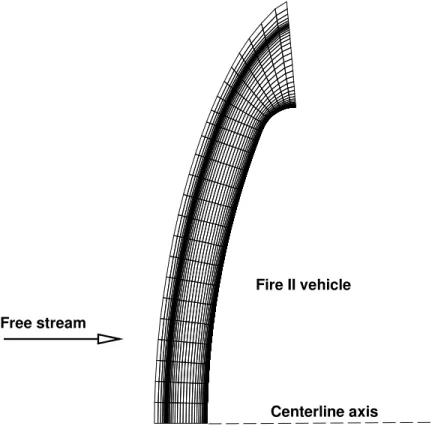
the benchmark LAURA/HARA results was reused for the present study by converting from a structured connectivity to an unstructured connectivity. The grid of Kleb and Johnston had 3185 nodes defining a 5◦ pie-shaped wedge of the axisymmetric vehicle and associated flow field. A side view of the mesh is shown in figure 1. In the context of FUN3D, axisymmetric source terms are not implemented, but rather the axisymmetric solution is enforced by the boundary conditions within a general three-dimensional simulation. The boundary conditions used for the present work are free stream, solid wall, extrapolation outflow, and axisymmetric symmetry, specifically thesymmetry 2 strongFUN3D option.
For the unstructured meshes the grid points were connected in a mixture of five- and six-faced elements, for a element mesh, and alternatively as four-faced elements for a tetrahedral mesh. The mixed-element mesh looks as in figure 1, and the tetrahedral mesh is similar, but appears as triangular, rather than quadrilateral, elements in a side view. Visible in figure 1 is clustering of the mesh toward the vehicle surface, on the right-hand side, and clustering to the bow shock, near the left-hand side of the domain. Lines of sight for the radiation calculations were chosen to be the lines traversing from the vehicle surface to the free stream boundary, each of which contained 65 mesh nodes.
Fire II vehicle
Centerline axis Free stream
Figure 1. Side view of the Fire II domain mesh with the mixed-element, as opposed to tetrahedral, connectivity.
conditions are taken from reference 5, and are listed in table 1. An eleven-species, two-temperature air model was used. The free stream mass fractions of N, O, NO, N+, O+, N+
2, O +
2, NO+, and e− were all set
to trace levels. The wall is modeled as completely catalytic, enforcing free-stream mass fractions. The wall temperature was uniform and constant, at 640 K. All calculations were at zero angle of attack and sideslip, matching the approach used by Kleb and Johnston3 for the benchmark comparison results.
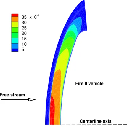
The flow fields computed using the mixed-element and tetrahedral meshes are portrayed as relative electron density contour plots, normalized by the free stream density, in figures 2 and 3, respectively. The bow shock is crisply captured on both meshes, and the plotted contours are generally very similar, although not identical, despite the two meshes having the same grid points. These differences in contour lines reflect the variability due to mesh connectivity and to the corresponding appropriate flux reconstruction schemes as implemented within FUN3D. In particular, observe in both figures the variations of the 35×10−6 contours as the centerline axis is approached. Because this is an axisymmetric simulation, and both the vehicle body and the bow shock are perpendicular to the centerline axis, flow-field contour lines would be expected to
Velocity 10.48 km/s Density 0.780 g/m3 Temperature 276 K Altitude 53.04 km Wall temperature 640 K N2 mass fraction 0.76 O2 mass fraction 0.24
Angle of attack 1◦ (but present simulation at 0◦) Side slip −4◦ (but present simulation at 0◦)
35 30 25 20 15 10 5 Fire II vehicle Centerline axis Free stream x10-6
Figure 2. Flow-field electron species densities, as fraction of free stream density, using mixed-element mesh.
35 30 25 20 15 10 5 Fire II vehicle Centerline axis Free stream x10-6
z, m
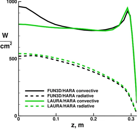
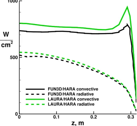
0 0.1 0.2 0.3 0 500 1000 FUN3D/HARA convective FUN3D/HARA radiative LAURA/HARA convective LAURA/HARA radiativeW
cm
2Figure 4. Surface convective and radiative heat transfer rates from present FUN3D/HARA coupling, using mixed-element mesh, and LAURA/HARA coupling results of reference 3.
also be perpendicular to the centerline axis. However, on the mixed-element mesh, figure 2, the region of highest contour level is reduced, as the contour line is angled away from the vehicle at the centerline. The opposite trend is seen on the tetrahedral mesh, figure 3, where the same region is increased as the contour line is angled toward the vehicle at the centerline.
The primary metric of interest for the present work is the radiative surface heat transfer rate, although the convective surface heat transfer rate, which forms the balance of the total surface heating, is an important parameter as well. Comparisons in the following figures use the LAURA/HARA coupling results of reference 3 as the benchmark. The heat transfer comparisons plot the heat-shield domain traversing from the symmetry axis, located atz= 0 m, out to the Fire II shoulder, just beyond z= 0.3 m.
Surface heat transfer rates from the present FUN3D/HARA coupling using the mixed-element mesh are shown in figure 4. The FUN3D/HARA convective heating, the solid black line in figure 4, matches the benchmark very closely away from the stagnation region, for z > 0.1 m, but has a poor qualitative trend in the stagnation region, rising to 20% above the benchmark on the centerline. The FUN3D/HARA radiative heating, the black dashed line, is within 5% of the benchmark, and in particular is 4% lower at the stagnation point, z = 0 m. The FUN3D/HARA radiative heating, while quantitatively close to the benchark, does display a slight qualitative divergence from the benchmark as the centerline is approached. This dip in radiative heating at the centerline on the mixed-element mesh corresponds with the reduction in highest electron density contour level discussed in conjunction with figure 2.
Considering the poor qualitative stagnation-point convective heating comparison to the benchmark for the mixed-element results of figure 4, axisymmetric stagnation point heating has long been of particular challenge for hypersonic simulations.22 In the context of LAURA, a singularity-free grid23has been utilized
in the past as one way to specifically “overcome[s] the problems associated with the axis singularity in the stagnation region. This singularity may induce erratic behavior in the calculated heat transfer distribution.” Similar trends in stagnation heating have also been reported for an unstructured-grid node-based finite-volume upwind scheme, characteristics shared with the FUN3D algorithm, for an entry capsule24 that had been tested at Mach-10 wind tunnel conditions. Because stagnation point convective heating was observed to
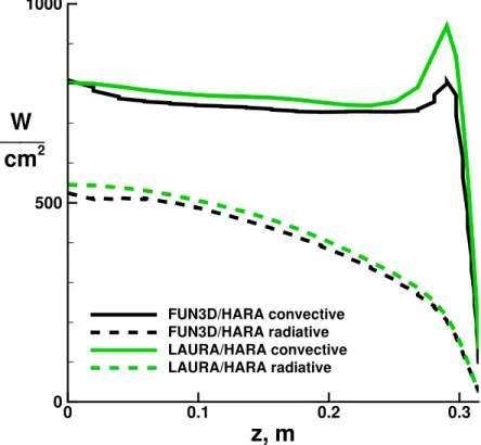
z, m
0 0.1 0.2 0.3 0 500 1000 FUN3D/HARA convective FUN3D/HARA radiative LAURA/HARA convective LAURA/HARA radiativeW
cm
2Figure 5. Surface convective and radiative heat transfer rates from present FUN3D/HARA coupling, using tetrahedral mesh, and LAURA/HARA coupling results of reference 3.
be sensitive to grid variations in the cited references, for the present work it was hypothesized that the mesh may have been too tightly clustered to the vehicle surface, and hence too highly stretched traversing away from the surface, causing numerical errors. The mixed-element mesh was then modified using the LAURA solution-adaption algorithm, such that the mesh in the bow shock region was kept fixed while increasing the nodal spacing at the vehicle surface. That combination of requirements also results in less stretching in the distances between nodes in the wall-normal direction. The spacing of nodes adjacent to the vehicle surface was increased by factor of 3.5; in the LAURA nomenclature the wall cell Reynolds number was increased from 4 to 14. The resulting FUN3D/HARA radiative heating rates were unchanged, as were the convective heating rates away from the stagnation region. At the stagnation point, this change in mesh spacing resulted in a lower convective heating by 23 W/cm2, a 2.4% change. Thus an overly tight mesh clustering to the vehicle surface was disproved as a leading cause for the poor qualitative stagnation point convective heating trend on the mixed-element mesh.
The coarsening of mesh spacing described in the previous paragraph also serves as a check on grid convergence. That coarsening was in the wall-normal direction, as stated by a factor of about 3, producing heat transfer changes of less than 3%. Grid convergence was also investigated by coarsening the original mixed element grid by a factor of 3 in the wall-tangential direction. The resulting changes in convective and radiative heat transfer rates were similarly small. At the stagnation point, convective heating rose by 2.1% and radiative heating lowered by 3.1%. At the shoulder, convective heating lowered by 1.6% and radiative heating rose by 5.4%.
Further attempts at rectifying the discrepancy in stagnation point convective heating between the FUN3D and LAURA results was not pursued within the scope of the present work. It is noted that suitable formu-lations for FUN3D hypersonic applications have only recently been formulated,19 and best practices with
regards to grid point distributions, mesh clustering, and other simulation parameters are still being learned. In particular, a general three-dimensional unstructured mesh would not have an axis singularity as in the present work, which may well be expected to affect the level of agreement at the stagnation point. It is also worth noting that LAURA implements a cell-centered algorithm, so that solution variables are not stored
z, m
0 0.1 0.2 0.3 0 500 1000 FUN3D/HARA convective FUN3D/HARA radiative LAURA/HARA convective LAURA/HARA radiativeW
cm
2Figure 6. Surface convective and radiative heat transfer rates from present FUN3D/HARA coupling, using tetrahedral mesh with decreased eigenvalue limiting, and LAURA/HARA coupling results of reference 3.
along the singularity axis, whereas FUN3D implements a node-based algorithm, with data stored at the nodes that define the singularity axis.
Heat transfer results using the tetrahedral mesh are shown in figure 5. The qualitative comparison of the FUN3D/HARA convective heating rates on the tetrahedral mesh to the benchmark data is the opposite as was observed for the mixed-element mesh. The agreement is best at the stagnation point, within 1%, and worst at the shoulder, with a 15% under-prediction from the present approach. Over the majority of the heat-shield the FUN3D/HARA convective heating is within 4% of the benchmark, biased low. The FUN3D/HARA radiative heating is slightly lower than the benchark, within 6%, on the tetrahedral mesh. Looking at the stagnation-point radiative heating from FUN3D/HARA, there is an increasing trend just as the centerline is approached. This uptick in radiative heating corresponds to the observed increase in electron density at the centerline, as discussed for figure 3.
It was hypothesized that the heat transfer under-prediction with the present method on the tetrahedral mesh may be due to excessive eigenvalue limiting, which could be producing increased artificial dissipation, and hence leading to lower heat transfer rates. Details of the eigenvalue limiting in FUN3D can be found in reference 19. To check the hypothesis, the eigenvalue limiting threshold was reduced in half, and a FUN3D/HARA solution obtained again on the tetrahedral mesh, leading to the heat transfer results shown in figure 6. Changing the eigenvalue limiting did not appreciably alter the radiative heating, but did noticeably reduce the convective heating, particularly in the stagnation region, where the heat transfer rate was down by 72 W/cm2, 9%. Although the results did not improve with decreased eigenvalue limiting, the flow field
solution clearly is sensitive to the level of eigenvalue limiting. At the present state of FUN3D development for hypersonic applications, the best-practice settings of the various algorithm parameters, such as for the eigenvalue limiting, are still being determined. It is worth noting that eigenvalue limiting within LAURA is tailored for both bow shock stability and boundary layer resolution, achieved because of different limiting strategies along the different structured grid coordinate directions. A similar tailoring of eigenvalue limiting has not as of yet been developed for FUN3D, because the unstructured-grid formulation does not lend itself to readily assumed alignment between flow features, such as a bow shock, and coordinate directions.
Considering prior assessments against the Fire II flight data, Palmer1 shows a compendium of ten pub-lished predictions for the stagnation point incident radiative flux, with values ranging from 500–700 W/cm2 at the 1643-second trajectory point. All of the present FUN3D/HARA radiative flux predictions fall within that range. Palmer1 also reports the effect on convective heating due to coupling radiation terms with the
fluid dynamic governing equations. Using the DPLR/NEQAIR coupling, the stagnation point convective heating was reduced by approximately 90 W/cm2with the inclusion of radiation coupling. For comparison,
comparing stagnation point convective heating from FUN3D with the FUN3D/HARA results shows about a 40 W/cm2 reduction due to radiation coupling.
IV.
Summary of Results
A long-term effort is in progress to extend the unstructured-grid CFD code FUN3D for hypersonic applications, a speed regime for which surface heat transfer is one of the more challenging engineering quantities of interest to accurately predict. For planetary entries or Earth return trajectories, shock layer radiation can be a large contributor to the overall surface heating. The present work coupled the HARA flow field radiation code to FUN3D for the simulation of high-energy flows. The software implementation of the coupling encapsulates the radiation source term computations within a single Fortran module of the FUN3D source code, and a coupled-radiation regression test has been incorporated into the FUN3D pre-release process. The FUN3D/HARA radiation coupling has been demonstrated for a Mach-31 Earth entry case, for the Fire II flight at the 1643-second trajectory point. Two approaches for defining the unstructured mesh connectivity were considered, using all tetrahedral elements and using a mix of five- and six-faced elements. In comparison to benchmark results from the literature, the radiative heating from the present work on either mesh slightly under-predicted, at worst by 6%. Convective heat transfer results from the present method were more varied. On the mixed-element mesh, the FUN3D/HARA convective heating matched the benchmark outside of the stagnation region, but over-predicted by 20% on the centerline. In contrast, using a tetrahedral mesh the present convective heating matched the benchmark at the centerline, but under-predicted by 15% on the shoulder of the Fire II capsule.
References
1Palmer, G. E., White, T., and Pace, A., “Direct Coupling of the NEQAIR Radiation and DPLR CFD Codes,” Paper
2010-5051, AIAA, June 2010.
2Gnoffo, P. A., Johnston, C. O., and Thompson, R. A., “Implementation of Radiation, Ablation, and Free Energy
Minimization in Hypersonic Simulations,”Journal of Spacecraft and Rockets, Vol. 47, No. 2, March 2010, pp. 251–257.
3Kleb, B. and Johnston, C. O., “Uncertainty Analysis of Air Radiation for Lunar Return Shock Layers,” Paper 2008-6388,
AIAA, Aug. 2008.
4Johnston, C. O., Hollis, B. R., and Sutton, K., “Radiative Heating Methodology for the Huygens Probe,”Journal of
Spacecraft and Rockets, Vol. 44, No. 5, Sept. 2007, pp. 993–1002.
5Johnston, C. O., Hollis, B. R., and Sutton, K., “Nonequilibrium Stagnation-Line Radiative Heating for Fire II,”Journal
of Spacecraft and Rockets, Vol. 45, No. 6, Nov. 2008, pp. 1185–1195.
6Perrin, M.-Y., Riviere, P., and Soufiani, A., “Radiation Database for Earth and Mars Entry,” Non-Equilibrium Gas
Dynamics—From Physical Models to Hypersonic Flights, NATO Research and Technology Organisation, Rhode St. Gen`ese, Belgium, Sept. 2009, pp. 8–1–8–40.
7Modest, M. F.,Radiative Heat Transfer, Elsevier Science, Burlington, MA, 2nd ed., 2003.
8Chambers, L. H., “Predicting Radiative Heat Transfer in Thermochemical Nonequilibrium Flow Fields—Theory and
User’s Manual for the LORAN Code,” TM 4564, NASA, Sept. 1994.
9Nicolet, W. W., “User’s Manual for RAD/EQUIL/1973: A General Purpose Radiation Transport Program,” Contractor
Report CR-132470, NASA, 1973.
10Park, C., “Calculation of Nonequilibrium Radiation in AOTV Flight Regimes,” Paper 84-0306, AIAA, Jan. 1984. 11Whiting, E. E., Park, C., Liu, Y., Arnold, J. O., and Paterson, J. A., “NEQAIR96, Nonequilibrium and Equilibrium
Radiative Transport and Spectra Program: User’s Manual,” Reference Publication RP-1389, NASA, Dec. 1996.
12Hash, D., Olejniczak, J., Wright, M., Prabhu, D., Pulsonetti, M., Hollis, B., Gnoffo, P., Barnhardt, M., Nompelis, I., and
Candler, G., “Fire II Calculations for Hypersonic Nonequilibrium Aerothermodynamics Code Verification: DPLR, LAURA, and US3D,” Paper 2007-605, AIAA, Jan. 2007.
13Johnston, C. O., Nonequilibrium Shock-Layer Radiative Heating for Earth and Titan Entry, Ph.D. thesis, Virginia
Polytechnic and State University, Blacksburg, Virginia, Nov. 2006.
14Johnston, C. O., Hollis, B. R., and Sutton, K., “Non-Boltzmann Modeling for Air Shock-Layer Radiation at Lunar-Return
Conditions,”Journal of Spacecraft and Rockets, Vol. 45, No. 5, Sept. 2008, pp. 879–890.
15Johnston, C. O., Hollis, B. R., and Sutton, K., “Spectrum Modeling for Air Shock-Layer Radiation at Lunar-Return
16Johnston, C. O., Gnoffo, P. A., and Sutton, K., “Influence of Ablation on Radiative Heating for Earth Entry,”Journal
of Spacecraft and Rockets, Vol. 46, No. 3, May 2009, pp. 481–491.
17Kleb, B., Schauerhamer, D. G., Trumble, K., Sozer, E., Barnhardt, M., Carlson, J.-R., and Edquist, K., “Toward
Supersonic Retropropulsion CFD Validation,” Paper 2011-3490, AIAA, June 2011.
18Gnoffo, P. A. and White, J. A., “Computational Aerothermodynamic Simulation Issues on Unstructured Grids,” Paper
2004-2371, AIAA, June 2004.
19Gnoffo, P. A., “Updates to Multi-Dimensional Flux Reconstruction for Hypersonic Simulations on Tetrahedral Grids,”
Paper 2010-1271, AIAA, Jan. 2010.
20Johnston, C. O., “Improved Exponential Integral Approximation for Tangent-Slab Radiation Transport,” Journal of
Thermophysics and Heat Transfer, Vol. 24, No. 3, July 2010, pp. 659–661.
21Cauchon, D., “Radiative Heating Results from the Fire II Flight Experiment at a Reentry Velocity of 11.4 Kilometers
per Second,” Technical Memorandum X-1402, NASA Langley Research Center, July 1967.
22Grasso, F. and Gnoffo, P. A., “A Numerical Study of Hypersonic Stagnation Heat Transfer Predictions,”Proceedings of
the Eighth GAMM Conference on Numerical Methods in Fluid Mechanics, Vol. 29, Vieweg, 1990, pp. 179–188.
23Gnoffo, P. A., Price, J. M., and Braun, R. D., “On the Computation of Near Wake, Aerobrake Flowfields,” Paper 91-1371,
AIAA, June 1991.
24Wood, W. A., “Multi-dimensional Upwind Fluctuation Splitting Scheme with Mesh Adaption for Hypersonic Viscous