Defence Engineering Group
The
Defence Systems
Engineering
Handbook
This handbook is intended to be a short guide to Defence Systems Engineering (DSE) that shares with the civil sector many of the principles of systems engineering, but applies them within the defence environment. It is a review of defence systems engineering taught by the Defence Engineering Group (DEG) at University College London (UCL) for the United Kingdom Ministry of Defence.
The guide contains a description of
* Defence Systems Engineering and how it differs from Systems Engineering.
* The role Defence Systems Engineering has to play in the acquisition of defence systems, including the CADMID acquisition cycle, and the roles of MoD, Dstl, DPA, DLO, the Armed Forces and industry
This handbook has been written for technical, administrative and Armed Forces personnel within MoD(UK), but will hopefully be of interest to a wider audience. The guide will also provide background reading to prepare students for courses in DSE.
The original work for this guide was performed by Shaun Emery, Kenneth Flatters, Andrew Jones, Robert Linton, Gary Steel, Steven Waller and Timothy Webb as an MSc team project. The material was then reviewed by the DEG staff and amendments/alterations incorporated. The revised material was edited for publication by Robert Linton.
For more information on this handbook contact:
The Defence Engineering Group
Department of Mechanical Engineering
University College London
66 – 72 Gower Street
London WC1E 6BT
The ideas and concepts in this document are those of the DEG. Although the DEG is partly funded by the MoD, the document does not reflect official policy and should not be interpreted as such. The ideas in the document are for guidance only, and the DEG accepts no liability for any action or loss arising from the use of this guide.
Table of Contents
Introduction...3
The Changing Political Environment... 4
New MoD Processes ... 5
System Engineering in the Defence Environment ... 6
The Defence Environment...7
Policy ... 7
Defence Planning ... 7
Missions ... 7
Tasks ... 8
Capability Management ... 8
Performance, Effectiveness and Capability ...9
Choosing Operational Capability ...11
High Level Defence Decisions ...11
MoD Planning Processes ...11
Balance of Investment ...12
Defence Systems Engineering and the MoD’s Acquisition Cycle...12
Defence Systems Engineering and the Through Life Approach ...13
Operational Analysis... 13
User Requirements... 14
Capture...14
User Requirement Document... 15
System Requirement Document... 16
Incremental Acquisition... 17
Through Life Capability and Capability Degradation... 18
Cost Forecasting... 19
Life Cycle Costs... 20
Risk ... 20
Integrated Logistic Support (ILS) ... 21
Procuring Defence Systems ...22
Design and Manufacture Processes... 23
System Design... 23
Structural Model ...25
Layout Model...26
Behavioural Model...26
Manufacture Process ... 26
Verification, Acceptance and Validation ... 27
Integrating Design and Manufacture... 28
Link to MoD Processes ... 28
In-service Operation ...29
Disposal ...31
Final Statement ...31
Glossary ...33
It is widely accepted that systems are far more complex than they used to be, but what is complexity? Several factors are involved, of which the most obvious are size, topology, technology and convergence, together with the multi-disciplinary nature of most modern systems. The fact that interfaces between system elements are increasingly dominated by software also compounds the complexity due to the intangible nature of software and the difficulty of removing the unwanted emergent properties commonly known as ‘bugs’.1
Introduction
Systems Engineering and Project Management are two sides of the same coin.1
Defence Systems Engineering was a new concept when the UK MoD originally funded the Defence Engineering Group (DEG) to teach an MSc course in Defence Systems Engineering (DSE) in 1991. The DEG course blended together Systems Engineering, analysis and management and in 1995 issued the formal definition of DSE as follows:
Defence Systems Engineering is the integration of those engineering, analysis and management activities necessary for the acquisition and operation of large and complex defence systems. It promotes the achievement of performance, cost and timescale targets in the uncertain environment of rapidly advancing technology and changing domestic and foreign policies.
Defence Systems Engineering differs from conventional systems engineering by virtue of the integration of management into the discipline. Defence Systems Engineering takes systems engineering forward from being a technical discipline used to create and develop systems and products, into a broader subject with an awareness of the policy and management issues which result in an ability to resolve problems in all aspects of the product throughout its life-cycle.
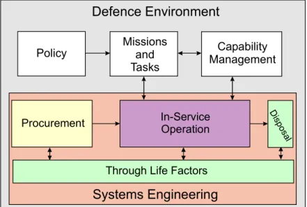
Defence System Engineering can also be considered as systems engineering in the defence environment. Within the systems engineering framework there are four major areas: through life factors, procurement of equipment, in-service operation and final disposal of that equipment. This guide consists of sections covering the defence environment and these four systems engineering areas. A simplified block diagram of this model of DSE is shown in Figure 1.
Defence Environment
Policy
Through Life Factors
Systems Engineering
Procurement In-ServiceOperation
D isp os al Missions and Tasks Capability Management
The Changing Political Environment
The political environment in which defence activities take place has been subject to major changes over the last two decades and is likely to remain subject to change and uncertainty for the foreseeable future.
The most significant change since the Second World War was the break up of the Soviet Union and the Warsaw Pact, bringing an end to the Cold War. These events have had a radical effect on all parties involved in defence activities and have drastically altered defence planning. The political environment continues to change, leading to risks and uncertainties. The planning process to provide capabilities to meet the emerging threats has become a great challenge.
To meet the requirements of this changing environment, the spectrum of Service activities has expanded. The Armed Forces have to be prepared to fight a high-intensity conflict, such as that experienced in the Gulf War. At the other end of the scale there are a variety of potential operations (peace-keeping, peace-making, humanitarian assistance etc.) where the relationship between military capability and operational success is quite different and more difficult to analyse or prepare for. In the latter type of operation the method of carrying out the action is primarily determined by political imperatives, the required speed of response and public perceptions.
As the armed forces of this country have decreased in size and the range of potential military tasks has increased, there is an increased use of joint and combined forces to conduct operations. Joint operations are those operations involving the use of units from two or more of the UK’s armed forces under a single commander. In addition to operations where joint force structures are implemented the UK is developing permanent joint structures such as the Permanent Joint HQ, Joint Rapid Reaction Force (JRRF) etc. Joint operations and structures allow the military capabilities to be considered in a tri-service manner, avoiding overlaps.
On a larger scale the same is broadly true of combined operations. In these the armed forces of two or more nations combine to undertake an operation. This is useful as it allows nations to co-operate with other nations for mutual support. The UK is prominent in many of the standing NATO organisations being the Framework Nation for the Allied Command Europe (ACE) Rapid Reaction Corps (ARRC) HQ and the Host Nation for HQ NAVNORTH.
The disappearance of a single, determinant scenario and threat has left defence planning with more contingencies to be considered. Military staff cannot easily draw upon years of planning and exercising against the Soviet threat to define future operational concepts and procurement programmes.
Nowhere is this more clearly seen than in the sphere of Asymmetric warfare. Here the threat is varied and complex and is not amenable to conventional military solutions. Not only could the threat appear in any sphere of the civil and military infrastructure, but it may also have no clearly defined host nation or organisation. The magnitude and destructiveness of this asymmetric threat has been vividly demonstrated by the
attack on the World Trade Centre on September 11th 2001. The paradox of this threat is that the more capable and powerful conventional alliance forces become, the more likely it is that a potential aggressor will resort to asymmetric strategies.
The range of eventualities in this diverse political and geographical environment has led to renewed interest in force generation, force deployment, logistics studies and methods to assess the performance of the UK forces. The substantial reduction in defence expenditure has increased the difficulties in defence planning and increased the care that must be taken with all defence acquisition decisions.
New MoD Processes
Systems never go wrong – it’s the people involved who do.1
The changes that have occurred in the global defence environment have been reflected in a transformation of the way the MoD goes about its business. The Strategic Defence Review (SDR)2 introduced the Smart Procurement Initiative (SPI), now known as Smart Acquisition, that focused attention on the following major areas:
· · · · · · · · · ·
Adoption of a ‘through life systems approach’, implicitly endorsing the principles of systems engineering.
The basing of acquisition decisions on perceived capability gaps
Integrated Project Teams (IPTs) bringing together all the main stakeholders in a project
Clear identification of customers and suppliers
A greater focus on trade-offs between system performance, cost and timescale
A more flexible approach to procurement, including incremental acquisition
The ‘CADMID’ procurement cycle with a simplified approval process A more open ‘partnering’ relationship with industry
More up-front investment
Formation of the Defence Procurement Agency (DPA) and the Defence Logistics Organisation (DLO)
Smart Procurement is covered in detail in The Acquisition Handbook – A Guide to Smart Procurement3 produced by the MoD Smart Procurement Implementation Team and available in booklet form or on the web-based Acquisition Management System (AMS).
System Engineering in the Defence Environment
As the name implies, Systems Engineering is concerned with studying a system in its entirety and not focussing on a single sub-system or technology area, as is often done by traditional single-discipline engineers. This implies an ability to define clearly what constitutes the system in question, in other words, ‘Where is the system boundary?’ This seemingly innocuous question lies at the heart of many system engineering problems. Clearly, a system boundary has to be defined in order that the system can be referred to as an entity, ie as a system.1 Major defence projects tend to exhibit the following range of attributes:
· · · · · · ·
It is common for defence projects to be large and expensive (such as aircraft and ships).
Defence projects are often at the leading edge of technology to provide the capability to meet a high technology threat; hence they are inherently more advanced with higher risks.
Defence projects generally have a long life from concept to disposal. This means that all the future benefits of a defence project are difficult to assess with confidence, particularly within the changing defence environment. The benefits of a defence project are difficult to express in financial terms. Defence projects are procured with public funds and, as such, are constrained by the necessity of public accountability and by political considerations.
Defence projects have many interested stakeholder organisations (Armed Forces, contractors, allies, taxpayers etc.) all of which have an interest in the project. Stakeholders may have divergent views on what constitutes success and how it should be achieved i.e. the armed forces seek capable equipment, contractors are looking for profits, allies expect complementary capabilities and taxpayers require responsible spending of public money. Defence equipment is often deployed rapidly and is expected to be operational and integrated with other local equipment/forces with limited setting up time.
Whilst it is acknowledged that civil projects share some of these attributes (a large bridge project would be expensive, medical breakthroughs can be high-tech, local government is constrained by budgets etc) defence projects are almost unique in that they display the full set of these characteristics.
It follows that the need for Systems Engineering in Defence projects is even greater than in similar-sized civil projects. In particular the use of DSE principles to integrate the requirements and expectations of a large and varied set of stakeholders and the complexities of managing large defence projects is crucial to the success of these projects.
The Defence Environment
After defining the system boundary as their first activity, system engineers must next consider the interaction of the system across its boundary with the environment. It is this interaction that gives the system its purpose, its raison d’être. In other words, a holistic view of the system itself is not enough. The interface between the system and its environment is central to systems engineering. The requirement specification for a system can be considered to be the definition of its external interface, since it determines how the system must react to and react on its environment. Systems engineers must therefore look upwards and outwards into the environment as well as downwards and inwards into the system itself. Engineers have traditionally been good at the latter, but have not always thought sufficiently about the former.1
Policy
The UK defence policy specifies the national aims and obligations, the potential threats to security and the context for UK defence activities. Defence policy is set by the government and articulated by the Secretary of State for Defence. The aim of Britain’s defence policy is to:
· · ·
Deter any threats to, and defend the freedom and territorial integrity of, the UK and its dependent territories. This includes the provision of support to the civil authority in countering terrorism
Contribute to the promotion of Britain’s wider security interests, including the protection and enhancement of freedom and democratic institutions and the promotion of free trade
Promote peace and help maximize the UK’s international prestige and influence
The way this policy is implemented changes annually and further guidance may be obtained from the MoD Annual Report.
Defence Planning
Defence planning is the process of translating the defence policy of the UK government into high level missions and defence tasks. To accomplish each of these defence tasks, the UK Armed Forces must deploy a set of complementary military capabilities. Each task may require several capabilities and each capability may support several tasks, which are generally assumed not to be concurrent. The UK’s Total Military Capability is composed of the capabilities required for the specific defence tasks, and determines the range of these tasks (and of other potential tasks which may arise) that the UK armed forces can undertake.
Missions
Arising from the defence policy, a number of defence missions have been established to provide high-level policies for service co-ordination. These missions are:
· · · · · · · · Peacetime security
Security of overseas territories Defence diplomacy
Support to wider British interests
Peace support and humanitarian operations Regional conflict outside the NATO area Regional conflict inside the NATO area Strategic attack on NATO
Tasks
The defence missions are further sub-divided into defence tasks for specific planning purposes. These tasks provide the detail required for force structure planning and run the whole gamut from operations other than war (OOTW) to warfighting tasks. Among the former are military aid to the civil authorities (MACA), counter-drugs operations and hydrographic and meteorological services (peacetime security) and disaster relief, peacekeeping and peace enforcement (peace support and humanitarian operations). The warfighting tasks include, or have included, the Gulf war (Regional conflict outside the NATO area), military home defence and deployment of nuclear forces (Regional conflict inside the NATO area or Strategic attack on NATO). In order to perform these defence tasks the UK armed forces need to have a certain level of military capability as described below.
Capability Management
‘British Defence Doctrine JWP 0-01’4 defines military capability as ‘the overall potential of the armed forces for combat or other operations’. From this it can be seen that aggregation of the various capabilities needed to undertake simultaneously all the defence tasks, or a chosen critical subset of such tasks, will give the total military capability needed by the UK armed forces. This then is a task-led approach to military capability.
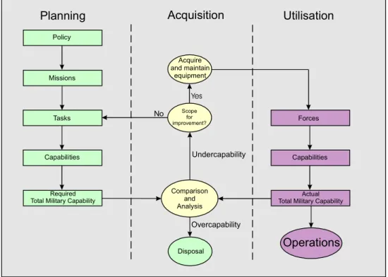
The alternative approach looks at the capability of existing military units and aggregates them through various force levels to produce the actual total military capability of the UK armed forces. Comparison of the required and actual total military capabilities will reveal areas of undercapability (capability gaps) that need to be ameliorated, or areas of overcapability that create opportunities for savings and rationalisation.
Figure 2, overleaf, illustrates this process and shows the two loops that create the required and actual total military capabilities that are compared during the capability gap analysis process. It is worth noting that the planning/acquisition loop has a timescale measured in weeks or months, the acquisition/utilization loop has a timescale measured in years. This means that although it is easy to amend the required military capability rapidly, the actual military capability will lag by some years. This indicates the level of planning and analysis needed to ensure that the UK’s actual total military capability is at the right levels when it is needed.
Policy
Missions
Tasks
Capabilities Capabilities
Required Total Military Capability
Forces
Actual Total Military Capability Comparison and Analysis Disposal Planning Utilisation Undercapability Overcapability Acquisition Scope for improvement? Acquire and maintain equipment Operations Yes No
Figure 2: Capability Gaps driving the Acquisition Process
To perform the bottom-up aggregation needed for this comparison, it is necessary to have methodologies for assessing a unit’s capability and for performing the aggregation.
Performance, Effectiveness and Capability
Generally weapon systems are defined in terms of their operational performance expressed as system parameters or operational performance parameters. In System Engineering terms these operational performance parameters can be considered as the emergent properties from the combination of functional sub-systems into a system. These parameters can be measured in factories or on ranges, but give little real information about battlefield performance.
It is of more use to consider weapon system effectiveness factors that account for the performance of military actions in an operational environment. In this context a weapon system can be considered as a platform, a launcher, projectiles, sensors and a command system. Typical examples of weapon systems are a warship, an AFV or APC, and a combat aircraft. Like operational performance parameters, weapon system effectiveness factors can be considered as emergent properties, in this case the combination of systems into a weapon system. A crucial difference between operational performance and weapon system effectiveness is that operational performance is absolute and weapon system effectiveness is relative or context based. This means that, as well as operational performance, effectiveness should also include a real battlefield environment, plausible enemy weapon systems and platforms and crew ability and training levels. Most of these would usually be thought to be outside a system’s boundary, but their inclusion marks the real transition from operational performance to weapon system effectiveness, and from Systems Engineering to Defence Systems Engineering.
A weapon system will have effectiveness facors, but military capability will only be developed when weapon systems are combined into an operational unit, such as a troop of tanks or a platoon of infantry. Some weapon systems, such as combat aircraft or warships, form in themselves an operational unit. The lower level units are only capable of delivering a single military capability, or in some cases a single military capability at any given time. This is an example of single function military capability (SFMC). Only when weapon systems with different capabilities are combined together into combat forces can multi-function military capability (MFMC) be developed. Examples of these types of force are all-arms battlegroups (ABG) and combined air groups (CAG), which not only have several capabilities but can deliver them simultaneously. It is this principle of simultaneity that draws the boundary between SFMC and MFMC rather than the capabilities of an individual unit.
As a rule military forces are organised to provide MFMC, for example, the all arms-battlegroup with direct fire, indirect fire and limited air defence capabilities, or the ASW frigate with primary ASW capability and secondary AAW and ASuW capabilities. These forces are intended to give more flexibility to force commanders by providing units that can be used for a variety of tasks. In constructing these MFMC forces, SFMC units are often used to contribute to many force capabilities, but often to only one at a time. This means that specific tasking of SFMC units must be considered carefully to develop the capabilities required at any given time avoiding over commitment. Definitions of operational performance, weapon system effectiveness, SFMC and MFMC are given in Table 1.
Operational Performance Parameters
The emergent properties from the interaction between a number of functional sub-systems’ functional performance parameters to produce a system’s operational performance parameters.
Weapon System Effectiveness
Factors
The emergent properties from the interaction between a number of systems’ operational performance parameters, the physical environment, enemy weapon systems, and human factors (crew ability and training) to produce a weapon system’s effectiveness factors.
Single Function Military
Capability The emergent properties from the interaction between a number of similar weapon systems’ effectiveness factors, human factors, command structure, maintenance and logistic support to produce an operational unit’s
sustainable single function military capability. Multi-function Military
Capability The emergent properties from the interaction between a number of different operational units’ single function military capabilities factors, human factors, command structure, maintenance and logistic support to produce a combat forces’ sustainable multi-function military capability.
Choosing Operational Capability
The earlier sections of this handbook have shown that the UK armed forces are required to undertake a diverse range of operations in a wide range of circumstances. Today, British forces will almost invariably need to operate jointly and often in combination with allied or coalition forces. To perform these missions efficiently DSE principles need to be applied to the command, structure, equipment and training of the armed forces as single service, joint and combined forces. Although DSE principles should be applied in these areas, the actual conduct of operations and training should be left in the hands of those most capable to perform them.
Potential capability gaps having been identified, analysis is required to ensure that an equipment is selected to fill the identified gap in the most cost-effective and time-efficient manner. To achieve this, analysis and planning is conducted at various levels of detail to gain an understanding of:
· · ·
how to fill the gap efficiently,
what is achievable within the defence budget, and how to determine priorities for acquisition.
High Level Defence Decisions
Most major operational capabilities can be provided in by a number of equipments. Each alternative carries its own strengths and weaknesses when applied to different situations. For example, ships, submarines and shipborne helicopters can all provide anti-submarine capabilities although some are more suited to a particular operational situation. In order to provide operational flexibility in different scenarios, a mix of equipment will usually be needed and careful analysis is required to ensure the optimum affordable mix is achieved.
As more and more equipments are designed for multiple roles, it is important to ensure that one capability does not adversely affect the ability of a platform to conduct its other roles. The impact of changes in one capability area must be considered for all other areas in order to maintain the best capability mix to perform the defence tasks and missions. The rapidly-changing defence environment places greater importance on other considerations such as readiness requirements, force generation processes, deployment of assets and the organisation of support services.
MoD Planning Processes
The procurement of defence equipment requires long-term planning as it often takes many years to bring a major equipment into service. The planning process starts with a strategic plan which addresses the high-level planning assumptions, provides the long-term vision and the future force structure, and attempts to identify the key drivers for change. The strategic plan provides an overview of the UK defence programme as a whole and drives the equipment plan. The equipment plan is the responsibility of Deputy Chief of Defence Staff (Equipment Capability) (DCDS(EC)) and contains the results from the balance of investment studies, the equipment requirements and costed options for each type of required capability.
Balance of Investment
Balance of investment (BOI) studies determine the best allocation of resources, within a fixed budget, in order to obtain optimum military effectiveness. BOI studies are conducted at high levels to influence defence policy where high level analysis looks at capability between and within capability groups. At a more detailed level, BOI studies allow comparison of different equipments that can provide an equivalent capability at different performance levels and at different costs. For example, a BOI study might compare a long-range strategic lift aircraft with transportation ships. BOI analysis is necessary to maintain a coherent and effective defence programme with the available resources. Equipment cost forecasts assist these studies to determine which new equipments are affordable and justifiable within the current force mix. These studies involve a comparison of force effectiveness at equivalent cost.
Defence Systems Engineering and the MoD’s
Acquisition Cycle
A system is what it is defined to be.1
Systems Engineering discipline specifies a number of principles that can be applied throughout the Acquisition Cycle. These principles can be summarised as:
· · · · · ·
Identification of all the project’s stakeholders and capturing and reconciling their requirements and expectations.
Adopting a through life approach to the project. Optimisation of the system, not the sub-systems.
Considering integration of the sub-systems when partitioning the system into sub-systems, as well as test and Evaluation at all levels.
Identifying all the interfaces within the system and between the system and its environment and other systems.
Remembering that everything is connected to everything else.
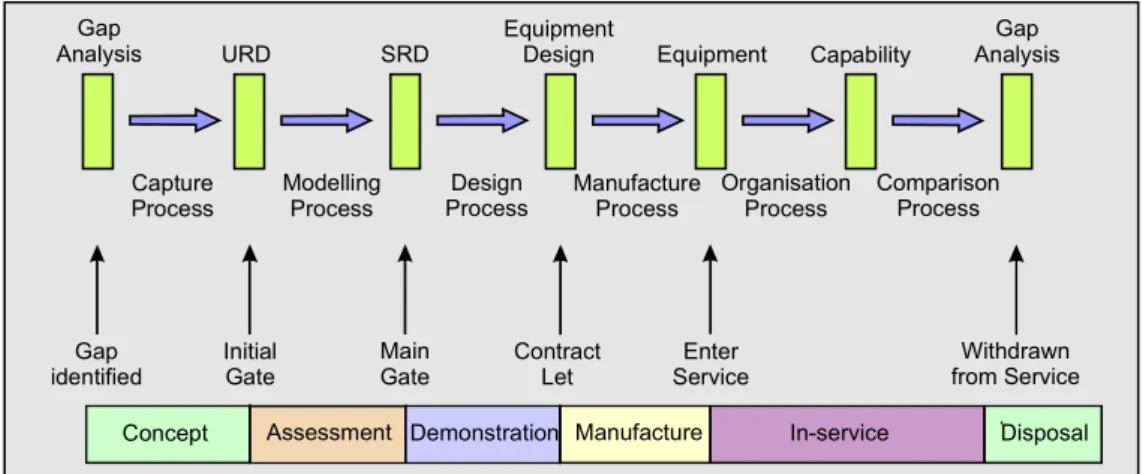
Defence Systems Engineering proposes that these principles should be applied at every stage of the acquisition cycle and to the management processes as well as to the technical processes shown in Figure 3. These principles should, therefore, be borne in mind when reading the remaining sections of this handbook.
The acquisition cycle used by the MoD(UK) has changed many times in the past, but is currently the CADMID cycle introduced as part of the Smart Procurement Initiative (SPI). This cycle has six phases (Concept, Assessment, Demonstration, Manufacture, In-service and Disposal) and two major approval points (the Initial Gate at the end of the concept phase and the Main Gate at the end of the assessment phase). This cycle shows a commitment to a whole life approach to acquisition, and as a simplified approval system to reduce the time taken to bring new projects to completion and the equipment into service. More detail of this cycle can be found in The Acquisition Handbook – A Guide to Smart Procurement.3
Figure 3 shows the broad relationship between the CADMID phases and the processes that make up the acquisition cycle. The process model shown in Figure 3 starts with the identification of a gap (undercapability) during the comparison and analysis process shown in Figure 2. This process model illustrates the processes and stages undertaken while going around the acquisition/utilization loop illustrated in Figure 2.
URD SRD EquipmentDesign Equipment Capability
Gap Analysis Gap
Analysis
Capture
Process ModellingProcess ProcessDesign ManufactureProcess OrganisationProcess ComparisonProcess
Concept Assessment Demonstration Manufacture In-service Disposal Gap
identified InitialGate MainGate ContractLet ServiceEnter from ServiceWithdrawn
Figure 3: The Process Model of the Acquisition Cycle
Defence Systems Engineering and the Through Life
Approach
Look upwards and outwards as well as downwards and inwards.1
One of the major findings from the 1998 SDR was the need to adopt a through life systems approach to provide a holistic design and development strategy, to overcome potential difficulties at subsystem interfaces, to formulate a comprehensive risk management strategy and hence to allow more accurate assessment of the overall cost of equipment. Systems engineering practices can ensure increased confidence in the forecast cost, time and performance of the system and the right balance of investment between the cost of acquiring new equipment and that of supporting in-service equipment can be achieved. This provides the armed forces with the right capabilities to enable them to successfully complete the tasks required of them.
The sections below highlight the many aspects of the through life approach used in defence systems engineering. It is current practice to record these activities in a through life management plan (TLMP), which is initiated during the concept phase and is developed continually and maintained as the project matures.
Operational Analysis
Dstl performs OA activities for defence equipments, commencing from a perceived capability gap, providing the evidence to inform the decision making process prior to equipment procurement. OA is a technical and scientific analysis of the military environment that helps to identify, analyse and provide quantitative and qualitative advice on problems such as:
· · · · · · · ·
Strategic Threat Assessments .
Planning, mounting, sustaining and supporting military operations. Operational effectiveness.
Tactical operations.
The tools used in OA for defence equipment are predominantly models, for example: Wargames – using the “military brain” to fight wars.
Simulations – based on combat rules and processes.
Synthetic environments – a virtual environment, in which modelled and real equipment can be tested, reducing the need for experiments in disparate locations.
Field Trials – using trained personnel and equipment to validate research. These tools need an operational context and a measure of effectiveness (MoE) to ensure that results can be compared accurately and consistently.
The output of OA studies must be integrated, using multidisciplinary systems engineering principles, with outputs from concurrent work on affordability and force development. OA output is used to guide more-detailed studies of procurement strategy, integrated logistic support etc.
User Requirements
Modern systems are much more than a single headful.1 Capture
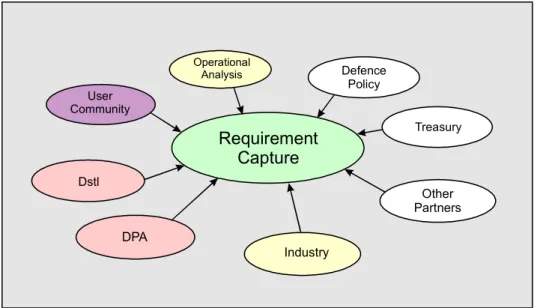
The genesis of any military equipment is the identified need. A chain of events, led by defence policy and initiated by the identification of a capability gap, derives this need. Requirements capture is the process by which the boundaries of new projects are explored. The process faces influences from many areas, both within and outside the defence arena, for example, defence policy, Treasury input, influence from industry. The requirements capture process should take advantage of lessons learned from past projects, using inputs from the DPA, Dstl, Industry or other military partners. The capabilities of other nations, as potential aggressors, and the level of ‘world’ military capability are also crucial inputs to the requirements capture process. Figure 4, overleaf, shows the multiplicity of stakeholder influences that contributes to the requirements capture process.
· · · · · Operational Analysis User Community Defence Policy Other Partners Dstl DPA Industry Treasury Requirement Capture
Figure 4: Requirement Capture
User Requirement Document
The user requirement document (URD) is used to express the need of the customer for a specific capability. It is the means by which the customer communicates and maintains the requirement throughout the life of the system. The URD should communicate the military capability of the system required without unduly constraining the scope of possible solutions i.e. it should not refer to contract, project or process requirements.
The purpose of a URD is to:
Communicate the user need to other stakeholders.
Provide an initial baseline against which trade-offs (between cost, performance and timescale), tender assessment and acceptance can be carried out.
Provide the criteria against which the system should be validated once the system has been accepted into service.
Maintain a link between the changing needs and actual capability achieved throughout the system’s life.
Underpin the business case presented during any expenditure approval process.
It is essential to identify all possible users of the proposed capability at an early stage and obtain their input to the URD. Other influences may come from suppliers, the general public, other Government departments and the enemy. In the UK MoD the central customer will have responsibility for the URD although the process of writing the actual document may be contracted out. Whilst the central customer has full responsibility for the URD, it will be essential for all stakeholders to be involved in the requirements capture process. Stakeholders in UK MoD projects will include the central customer, the user community (termed the Second Customer), DPA, DLO, Dstl and industry.
The URD is created during the Concept phase and is maintained for as long as the requirement exists. An initial version of the URD will be used to support early approval for project expenditure (initial gate approval), with a refined version used to support later approvals (main gate) along with the system requirement document. After main gate the URD should be reviewed at regular intervals and amended if required, to ensure that it represents the current user need. Although changes may be required to the URD in these later stages these may not filter down to the system requirement document unless considered essential, as it is important to contract against a firm requirement. Any forecast gap between the URD and SRD will represent an emerging capability gap which may need to be addressed by a capability upgrade.
System Requirement Document
A system requirement document (SRD) is a complete description of a system that will meet the user needs as stated in the URD. The SRD provides a description of the required system behaviour but does not prescribe a technical solution. Effectively, the SRD describes a high level model of the system, which promotes discussion, trade-offs and optimisation, prior to the development of a system design. As well as providing the focus for system specification leading to contract placement, the SRD must be maintained throughout the lifecycle of the system detailing the baseline system requirements. An audit trail must be maintained from the URD to the SRD to show the origin of every requirement and how the system will satisfy it.
The SRD is the means by which the system requirements are developed, communicated and maintained in order to:
· · · · · · · ·
Provide a basis for negotiation and agreement, between customer and supplier(s), on the system performance.
Explore possible trade-offs between system performance, timescale and whole life cost, before commitment to design or contract.
Ensure that those requirements agreed as affordable and achievable are reflected in system development.
Provide a solid foundation for system design, expressing the whole system in the language, terms and detail against which the system can be designed, manufactured, delivered and accepted.
Specify legitimate constraints on system design.
Focus on risk reduction leading to acceptable levels of risk prior to contract placement.
Underpin the business case for system development.
Provide the baseline for whole-life system performance against which user needs and system capability can be monitored.
As with the URD, the development of the SRD should involve all stakeholders in order to obtain a common understanding between all parties. The SRD is owned by the IPT leader and is a translation of the Customer’s requirements into system terms. It will be produced by the Requirements Manager (RM), who is accountable to the IPT leader. The RM will ensure there are suitable processes in place to define the structure of the SRD and manage the interface with the URD. The IPT, as a whole,
will be responsible for the actual capture and specification of the systems requirements.
The majority of the work on the SRD involves the IPT assessing options in the development of trade off considerations. During the early stages of the lifecycle there may be more than one SRD satisfying a single URD. This allows for a variety of disparate system options to be considered during assessment. During the demonstration of feasible development options, one technology solution is chosen for further development and the project team refines the SRD, trading off cost, time and performance to optimise the solution. By the end of the demonstration phase, the SRD will be frozen to allow progress through to approval for development and production expenditure. After approval, contractors will bid against the SRD that will form the basis of the contract. The SRD will be updated, as required, throughout the life of the system to reflect trade-off decisions, incremental acquisitions and approved system enhancements. During manufacture the SRD will be used to track delivery, integration and acceptance of the system. Similarly, when the equipment is in service, the changing needs and performance of the system will be assessed against the SRD.
Incremental Acquisition
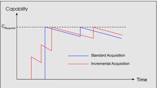
Defence systems are increasingly reliant on rapidly changing technologies such as software and electronics. With the current level of complexity in defence projects, it is increasingly difficult to procure systems as a single deliverable. Long procurement timescales and the changing environment can lead to equipment which, when entering service, is found to be obsolete or fails to meet the needs of the user. Incremental Acquisition is a strategy which aims to deliver a baseline requirement followed by a planned upgrade programme such that the equipment can be brought into service rapidly and progressively updated to ensure it meets the changing needs of the user and remains up to date. Other advantages for following a planned incremental upgrade path are that risks can be reduced, technologies closer to the “state-of-the-art” can be inserted and it allows feedback from the user community to be incorporated into future upgrades.
Commercial-Off-The-Shelf (COTS) equipment is often at the forefront of technology as producers need to maintain a competitive advantage. This can be exploited for applications such as information technology where state-of–the-art equipment is required and due to its availability can be utilised in an Incremental Acquisition programme.
Major platforms hosting a wide range of weapon systems and diverse functionality often experience ongoing change to their system and sub-system requirements. Adopting a through life systems approach to defence capability means that the overall advantages and disadvantages of incremental acquisition of such systems can be properly assessed.
Incremental acquisition allows the baseline requirement to enter service quickly. More complex functionality can be inserted progressively, allowing more time for trade-offs between effectiveness, time and cost on complex parts of the system design.
Incremental acquisition does however require careful management, especially through the approvals process. A project adopting incremental acquisition will have a number of technical and financial uncertainties when submitted for main gate approvals. An overall cost limit for the project with target cost and performance envelopes for each planned improvement must be set. As each increment is achieved, it will be necessary to re-set the target cost and the performance envelopes for each subsequent increment.
Through Life Capability and Capability Degradation
The capability of defence systems will degrade with time as the military equipment of other nations is renewed or upgraded. This means that equipment will need to be upgraded or replaced to maintain a military capability subject to constraints of cost and availability. The capability generated by these upgrades should not exceed the initial capability that the equipment was capable of providing without recourse to the approving authority.
Incremental acquisition (IA) introduces a philosophy where equipment is brought into service with a low initial capability and then improved at planned stages to develop its capability. Unit, force and total capabilities will be affected by new equipment entering service and the withdrawal of obsolete equipment. As systems become older they will be more difficult to support and the availability of these systems for military operations will be reduced. This effect will exacerbate the problem of increasing world capability and increase the downward slope of the capability degradation graph, shown in Figure 5. Standard Acquisition Incremental Acquisition Capability Time CRequired
Figure 5: Diagram of Standard and Incremental Acquisition Producing Capability While a system is in service it must be supported to maintain its operational capability. The current maintenance philosophy is to consider a system’s availability for operations. This availability is a function of reliability and maintainability, and these in turn are functions of mean time between failure (MTBF) and mean time to repair (MTTR), and of logistic delays. MTBF and MTTR are used to determine the range of spares that are needed and how many of each type of spare are required. Any upgrades of the system will probably require this scaling and ranging exercise to be repeated. Throughout the time that the system is in service, the support represents a
cost to the MoD. As the system ages this cost will increase and this is particularly true for systems that the MoD keeps in service beyond a normal commercial lifetime. Constant feedback to the capability working groups will help to assess the system’s current capability against the capability required to achieve the defence tasks.
Cost Forecasting
In placing contracts for goods and services MoD(UK) has a duty to safeguard public money by vetting the prices proposed by industry, ensuring that they are fair and represent good value for money.
To support this aim the MoD utilises cost forecasting models in each of the following areas:
· Budgetary. Time profiles of acquisition expenditure are forecast annually which contribute to the construction of 4 and 10 year spend profiles, known as Short Term Plans (STP) and Equipment Plans (EP). While the STP/EP process determines whether financial resources can be found for a potential project in the programme and ensures smooth department expenditure, the responsibility for detailed scrutiny and advice to Ministers on individual major equipment proposals rests with the Investment Assessment Board.
·
·
Dstl uses equipment cost forecasts in balance of investment (BOI) studies to identify which new equipments merit a place in the UK service force mix. The cost effectiveness of each type of equipment can be compared either on grounds of common through life cost or common effectiveness. Direct and indirect costs associated with the equipment must be included within the comparison.
Selection for procurement. From the BOI studies will emerge a particular class of equipment that might best fill a future capability need. Several procurement options may be available to satisfy this capability gap. A combined operational effectiveness and investment appraisal (COEIA) is carried out to inform the decision as to which system should be procured on the basis of cost effectiveness. Arrangements for different warranty policies, contractor support, the private finance initiative (PFI) etc. are included in the investment appraisal. A COEIA may be required at any stage in the procurement process where a number of options need to be considered.
· Before cost forecasting can begin, each of the alternative equipment programmes must be defined comprehensively and recorded in the master data and assumptions list (MDAL). The MDAL will include all factors that affect cost, including technical description, definition of procurement strategy, training plans, policy on inclusion of indirect costs, delivery schedule, the expected level of operations and the economic conditions to be used in the cost forecast.
· Early cost forecasts are based on high-level assumptions and these forecasts are refined throughout the equipment life cycle as more accurate information becomes available. The models that are used to derive cost forecasts are highly dependent upon the accuracy of available information and no single model is suitable for all purposes.
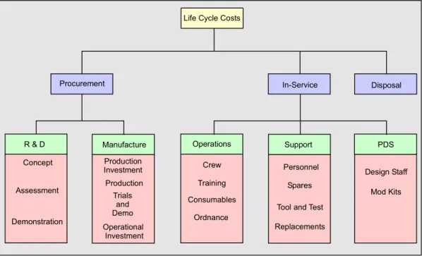
Life Cycle Costs
The Life Cycle Costs (LCC) of equipment is the total cost directly associated with it from concept to disposal. The components of LCC are related to project phases, as shown in Figure 6. Production Investment Operational Investment Trials and Demo Demonstration Concept Production Training Replacements Tool and Test
Spares
Design Staff Procurement
Manufacture
R & D Operations Support
Disposal In-Service
PDS Life Cycle Costs
Mod Kits Personnel Ordnance Consumables Crew Assessment
Figure 6: Life Cycle Costs
It is important to take account of all cost elements prior to equipment selection since most errors in cost forecasting arise from omission rather than misjudgement.
Through life costing is further complicated by variations in operating costs. For certain systems the through life cost is dominated by operating costs e.g. a warship where the long in service time and high running costs outweigh the initial procurement cost. The LCC of other systems may be dominated by procurement costs e.g. a guided missile which may be stored in a silo for the majority of its life, requiring little maintenance. Disposal costs must be considered at the outset as they can be large for environmentally hazardous equipments such as nuclear submarines, but can be negative for ships, aircraft etc – which may be sold to other nations.
Risk
Risk management has always been an important aspect of disciplined project management. The focus on through life cost procedures has increased the need for formal risk management. A risk manager is appointed early in the project lifecycle and is encouraged to involve all stakeholders in a formal risk identification process. Study
groups are used to look at all internal and external risks that may be associated with the project. Any risk that may impact on the success of the project should be identified early so that it can be recorded and managed appropriately. Risks are recorded in the risk register that is continually updated with the latest identified risks.
A risk can be defined as an uncertain event which may impact on the project in various positive or negative ways and hence can either be a threat or an opportunity. For the best chance of success, project risk must attract the appropriate level of management attention. Risks can be avoided, mitigated, accepted or transferred. Avoiding a risk involves steering the direction of the project such that the risk can no longer have an impact. Mitigating a risk involves using resources to put contingency plans in place such that the impact of the risk is reduced to an acceptable level. In certain circumstances risk will have to be accepted. Such risks are usually ones with very low probability of occurrence (but incur expense to prevent) and are particularly hard to mitigate against, such as project cancellation or a change of Government. Risks can be transferred where the management of the risk is best placed with another party, providing they are willing to accept it. Risks should not be transferred as a matter of course; those risks that cannot be avoided should be managed by the party best placed to accept or mitigate the risk.
Formal procedures for risk management are readily available and the DPA uses a common tool set which aims towards a consistent and thorough approach. For a comprehensive description of risk management practices and procedures refer to the Project Risk Analysis and Management – A Guide published by the Association for Project Management, March 1992.
Integrated Logistic Support (ILS)
Integrated Logistic Support (ILS) is a disciplined management approach, affecting both MoD(UK) and industry, aimed at optimising value for money throughout the equipment lifecycle. ILS considers all aspects of supporting the equipment and as such should be used to influence the earliest stages of the acquisition cycle. The SDR has reinforced the MoD’s commitment to the application of ILS as a key Business Process for achieving reductions in LCC in association with Systems Engineering Principles. The application of ILS within the MoD is prescribed by Defence Standard 00-60 Integrated Logistic Support, that IPTs will be required to tailor to suit the particular equipment programme.
The major goals of ILS are to,
· · · ·
Influence equipment design early enough to be effective Develop support resource requirements
Acquire resources
Provide the required in-service support at the optimum LCC
The continued advances in information systems (IS) and the ability to exchange electronic data has facilitated the application of Computer Integration of Requirements, Procurement and Logistic Support (CIRPLS), bringing benefits in the acquisition and in-service phases. ILS policy is driven by the Chief of Defence
Logistics (CDL) to assist IPTs. The lessons associated with the support of current in-service equipment must be fed back into replacement equipment programmes.
ILS addresses a wide range of support areas in an integrated manner. The ILS elements, as defined by the ILS Defence Standard, are listed below.
· · · · · · · · · · · · · · Maintenance planning Supply support
Support and test equipment (S&TE) Reliability and maintainability (R&M) Facilities
Manpower and human factors Training and training equipment Technical documentation
This list is neither exhaustive nor prescriptive and the applicability of each element will vary between projects. This list can be expanded to include the following, for example:
Design influences
Packaging, handling, storage and transportation (PHS&T) Non-Operational Computer Resources (NOCR)
Life Cycle Costing (LCC)
Crisis Resupply from Industry Procedures (CRIP) In-Service Monitoring of Logistic Performance
Recognising that all projects are different, the tasks and requirements are designed to be flexible and must be tailored to fit each project. This prevents ‘blanket’ applications of ILS to small projects and inadequate provision on larger, more complex projects.
The principal tool of ILS is Logistic Support Analysis (LSA) which applies a set of standardised tasks with defined objectives and outputs. LSA is a structured method of analysing items of equipment as they are being developed. The aim is to identify any features of the design that could result in unnecessary expense through the equipment life cycle. Once identified, these ILS elements can be the subject of trade-offs to amend the design to reduce future cost.
The LSA data is held centrally in a Logistic Support Analysis Record (LSAR) so that it is readily accessible to both design and support areas. This allows data to be entered once and read many times, in accordance with the CIRPLS philosophy, reducing duplication of effort and improves the consistency of the data used.
Procuring Defence Systems
Having partitioned a system into its main sub-systems, these in turn can be partitioned into assemblies, which in turn can be partitioned into sub-assemblies and so on down to the level of indivisible
components such as nuts and bolts. There is no good reason why sound systems engineering principles should not be applied at all levels of partitioning. In other words, a hierarchy of systems exists, with each system at any level being composed of smaller sub-systems whilst at the same time being merely a sub-system of a higher level.1
Design and Manufacture Processes
Classically Systems Engineering has been thought of as a set of processes or tools to be used in the design and manufacture of a system. It has already been explained that Defence Systems Engineering applies these same processes and tools to management and other non-technical processes, but in this section we shall be considering Systems Engineering in its purest form.
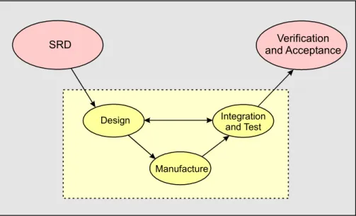
The design and manufacture processes take the SRD as their starting point and conclude with the verification of the system prior to installation and validation in its working environment. By their very nature the processes of design, building and testing are iterative and continue throughout the system design and manufacture, shown in Figure 7. Systems Engineering principles stress the importance of feedback throughout the design and manufacture processes and in particular the need to consider integration and testing of systems when partitioning the system into sub-systems during the design process. This must be done at every level of partitioning undertaken during system design.
Design Integration
and Test
Manufacture
SRD and AcceptanceVerification
Figure 7 - Design Process ~ Simplified Vee Diagram
System Design
One man’s sub-system is another man’s system.1
System Design is the process whereby the architecture of the system is considered, using Systems Engineering principles, in terms of structure, behaviour and layout, taking into account the logistic needs of the customer and the equipment. During this phase the system is successively partitioned through the various design levels as shown in table 2.
Design Level
Level Name Mechanical
Component Example Electrical Component Example 1 Weapon System
2 System Propulsion Unit Thermal Imager
3 Sub-system Transmission Signal Processor
4 Sub-system element Gear Box Rack of boards
5 Assembly Gear change assembly PCB
6 Component Cog Resistor
Table 2: Partitioning Levels for System Design
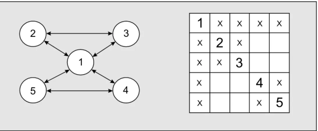
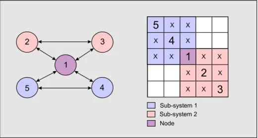
Careful consideration must be given to the interfaces between the elements of the system and the interface with the environment. A useful Systems Engineering tool to use during this process is the Interface Matrix. This can be used to ensure that all interfaces within the design are included in the design process and to help identify nodes and other key features of the design. Figure 8 shows a simple network and the interface matrix that describes the interfaces within that network representing a sample assembly.
To get the most from an interface network, Systems Engineering principles suggest that the components should be arranged so that the interfaces lie close to the centre line of the matrix. This process is called diagonalising the matrix and is illustrated in Figure 9. The diagonalised matrix can be used to show sub-systems, nodes and chains in the design. In Figure 9 the two sub-sytems, 123 and 145, can be clearly seen as closely interlinked sections of the interface matrix. In addition the fact that component 1 is a node can be seen by its place in both sub-systems and that it has an interface to all the other components.
1 2 3 4 5
1
2
3
4
5
X X X X X X X X X X X X1 2 3 4 5
1
2
3
4
5
X X X X X X X X X X X X Sub-system 1 Sub-system 2 NodeFigure 9: The Diagonalised Matrix Structural Model
Don’t divide where you can’t reassemble and test.1
This is often represented as a hierarchical block diagram of the system, Figure 10, showing the partitioning into sub-systems etc. This type of architecture shows the interfaces between the system elements and gives an indication of system complexity and difficulty of integration. When used in conjunction with an interface matrix, or an interface matrix for each level, this model is valuable for showing what is connected to what and where information needs to be shared across an interface.
In practice there may be several levels of partitioning and integration. As already described, Figure 10 illustrates the Systems Engineering principle that, when partitioning, it is necessary to consider how the partitioned elements will later be integrated and tested. This will involve the early development of an integration strategy and test specification.
Feedback Feedback Partitioning Partitioning Integrate and Test Sub-systems Verification and Validation of System SRD Accept
Layout Model
The layout model defines the topological and physical configuration of system elements and the system packaging. This model develops considerations of size, weight, power, ease of maintenance etc. The major difference between layout and structure is that layout represents the physical reality of the system e.g. PCB layout, architectural drawings etc. whereas structure shows the interfaces and connections e.g. a telephone network.
The layout model can reveal some of the requirements of the design such as chassis size, power requirements and overall weight that are not evident from any other model of the design.
Behavioural Model
The behavioural model is concerned with the system inputs and outputs. The behavioural model will indicate the types of interfaces that are present, for example, mechanical, hydraulic, electrical etc. and the constraints imposed by the interfaces. Unlike the structural and layout models, which are static, the behavioural model shows system dynamics and can be used as the basis for specifying a system-testing regime.
All three architectural models (structural, layout and behavioural) must be considered jointly in system design as they are necessary to represent the complete system. Completion of the structural, layout and behavioural models yield important benefits such as clear configuration control, defined working practices, quality processes etc. Also, at the end of the architectural design process a catalogue of reusable design elements can be established.
Manufacture Process
Manufacturing can begin once the system has been designed and assessed. Some components and sub systems may already be available ‘off the shelf’; the remainder will need to be designed and manufactured. During manufacture, components are integrated into assemblies, sub-systems elements, sub-systems and ultimately the system. A Systems Engineering ‘build a little, test a little’ philosophy should be adopted during this integration process, as shown in Figure 11. When testing it is important to ensure that the test is appropriate for the level of integration. The individual elements should be tested and then, once integrated, the emergent properties of the resulting unit should be measured and checked with the SRD.
Sub-Assembly Sub-Assembly Test Test Test Unit
As described previously, the integration strategy and test specifications will have been established during the design process. Sufficient time should be allowed in the project plan for problem solving and reiteration of the testing in the event of test failure. This is especially valid for the development of system software, which can be difficult to test, and for which metrics of progress can be difficult to define and measure. Testing will be undertaken at all levels up to complete system testing where verification will be carried out against the system requirements as described in the SRD. This is the last process before the system enters acceptance trials, which are performed in an appropriate operational environment.
Verification, Acceptance and Validation
Verification determines whether the system meets the requirements specified in the SRD. Confidence that the design satisfactorily meets the requirements can be gained during sub-system tests. Integration and progressive acceptance, leading to delivery, should be recorded against the system requirements. Staff dealing with integration, verification and acceptance should be involved during the initial requirements capture to ensure successful integration and acceptance. Integration and verification is always a compromise, a balance between testing and available resources should be planned. Testing everything would increase timescales and cost beyond acceptable levels so it is important that confidence is progressively gained during integration such that acceptance tests are concentrated at system level.
The SRD is the principal tool for establishing acceptance criteria for the system. The delivered system should be accepted against a pre-defined subset of criteria, which encompass the SRD. In order for the IPT to gain more confidence in a complex system, a variety of tests, leading to acceptance, may be undertaken at lower levels than the SRD. Links to URD statements will provide early confidence that the operational user will be satisfied and that the system will pass validation testing.
Validation determines whether the system meets the expectations of the user, in an operational environment, as defined in the URD. Therefore it is imperative to consider, during user requirement capture, how and to what extent the system will be validated to prevent problems when the equipment enters service. Validation involves integrating the end product, support systems, such as the operational and maintenance systems, and legacy systems which may have been created separately. An extended period may be required where staff are trained and become part of the operational capability. Validation testing may, therefore, be a multi-stage process. Although validation is performed in a largely in-service environment, for reasons of economy some parts of the external environment may be simulated, for example, early stages of the validation of an air defence system may use simulated radar data or recordings of previous live data in a simulated environment.
Integrating Design and Manufacture
Traditionally design and manufacture have been performed sequentially and no manufacture of components has started until the total design has been completed, tested and approved. This was not always strictly the case as many ‘stock’ items, such as nuts and bolts, cable conduit, fan trunking etc., were produced for later integration. However, it was generally agreed that the design had to be certified prior to the production commencing.
Advances in computers and Information Technology (IT) have allowed new concepts to be applied to the design and manufacture of defence equipment. Computer Acquisition and Lifecycle Support (CALS) allows for concurrent engineering to be applied to both design and manufacture. A key part of this new approach is the concept of a central, electronic data base which contains the sum of the structural, layout and behavioural models integrated into one set of data, which can be used to create an overall equipment model. This overall model contains data on all the physical and electrical interfaces within the equipment and allows rapid and effective partitioning into systems, sub-systems, assemblies etc.
Since only one shared database exists, design of individual sub-systems can be conducted in parallel with a consequent saving in design time. The same is true of manufacture and, if the database is used to provide data directly to computer guided cutting machines, remote manufacture and construction of sub-systems becomes a possibility. In theory it would be possible to begin manufacturing some sub-systems before the design stage was complete, but this remains risky unless the process were controlled very rigorously.
Concurrent engineering incorporates systems engineering principles to ensure separately designed and manufactured sub-systems integrate to form a coherent system. However, concurrent engineering is only applicable in a limited set of circumstances within the design and manufacture processes. So concurrent engineering remains a subset of the wider reaching systems engineering.
Link to MoD Processes
The procurement of defence systems is the main activity of the DPA which uses some of the ideas and concepts outlined in this section, combined with the more detailed processes defined in the Acquisition Management System (AMS)5 on the MoD(UK) Website. The AMS refers to the importance of the use of systems engineering principles during the procurement process. It is important to recognise that the procurement of defence systems is only a part of the overall acquisition activity and that defence systems engineering takes a broader view of the acquisition activity, supporting all phases of the CADMID cycle.
In-service Operation
Once the manufacture phase of the project has been completed the ‘equipment’ will enter service with the Armed forces. In this case equipment should be taken to mean a weapon systems, sub-system (such as a launcher, sensor etc.) or software. It must be remembered that the purpose for which the equipment has been procured is to deliver military capability.
Earlier in this handbook it has been proposed that military capability will only be produced when weapon systems are combined into an operational unit. For the purposes of this handbook examples of the lowest level of operational units are a troop of tanks or artillery or a platoon of infantry. (This example is for the army, but similar examples could be drawn for the RN, the RAF or a ‘purple’ joint force.) Systems Engineering principles indicate that the interfaces between these lowest levels of operational units are of the greatest importance when they are aggregated into larger forces. These larger forces could be single type, such as an infantry battalion, a tank squadron, an artillery battery or they could be multi-type such as an all arms battlegroup. In fact it could be argued that the sum of these interfaces is the Command structure of the larger force. It is not proposed to follow this argument any further in this handbook. Suffice it to say that the integration of numbers of low level units, logistic support, operator and maintainer training etc. produces the sustainable military capability of the Armed Forces.
Figure 12 illustrates the post manufacture parts of the equipment’s life cycle. Once the equipment enters service, on its In Service Date (ISD), it is organised into operational units and starts producing military capability. However, military capability is relative in nature and will degrade as the world military capability improves. In time it will have degraded to such an extent that a capability gap occurs and an upgrade programme will be initiated. This could happen several times during a major equipment’s life. Eventually no upgrade to the equipment will be possible and either the capability gap will be accepted or a new piece of equipment will be acquired. At the new equipment’s ISD the equipment being replaced will be withdrawn from service at its Out of Service Date (OSD) and scheduled for disposal. Figure 12 shows the ideal situation with the replacement equipment’s ISD coinciding with the existing equipment’s OSD. In reality this may not occur. If the ISD is after the planned OSD either a capability gap will exist or the existing equipment will be ‘run on’ until the replacement’s ISD. This would have considerable cost and, possibly, manpower implications for the Armed Forces. Similarly if the OSD is after the replacement’s ISD, there will be an overcapability and opportunities for savings by early disposal. Once again the correct use of Systems Engineering principles should enable programmes to run to time and prevent expensive overruns.
C A DM ISD C apab ilit y Re qu irem en t Capabi lit y Req ui rem ent C A D M C a pabi lit y Ga p U p gr ad e C A D M Ca pa b ili ty Ga p Upgr ade C A DM In iti a l pr oc ur emen t C apab ili ty Ga p No up gr ade po ss ibl e Repl ac emen t equ ip ment In -s er vice equi pm ent 1 Dis po sal equ ip me nt 1 D isp osal eq ui pm en t 0 In -servi ce equi pm en t 2 In -s er vice equi pm en t 0