Ethernet in the First Mile over Copper (EFMC)
A Tutorial
Overview
While the demand for Ethernet services continues to grow, the challenge of delivering these services to end users remains a significant roadblock in the way to fulfill this demand. Until recently, fiber was the only way to deliver high speed Ethernet services. However, the limited coverage of the fiber network required an alternative solution to complement it and make Ethernet services ubiquitous. Twisted-pair copper wiring (plain old telephone line) dominates the local loop from the home or curb to the Central Office—the “first mile.” Running Ethernet over this copper wiring is an ideal way to exploit the existing voice-grade copper infrastructure, within residential neighborhoods as well as business buildings. Using the existing voice wire infrastructure keeps deployment costs to a minimum: there is no need for new cabling inside or outside the residence or business and service providers enjoy new returns on their already amortized assets.
Hence, one of the solutions being touted in the IEEE Ethernet in the First Mile (EFM) standardization process is EFM over Copper, or EFMC. Running over existing Category 3 wire, EFM has set goals for a short reach option of at least 10 Mbps up to at least 750 meters, and a long reach option of at least 2 Mbps up to at least 2700 meters. While the EFM committee has set these objectives as a minimum, the standard does not limit systems to these rates, and in fact most EFMC systems available today support much higher rates. Additional mechanisms for bonding of multiple copper pairs allow an even higher throughput, providing a viable alternative for end-users served only by copper.
There are limited EFMC deployments today, but the EFM (802.3ah) standard will eliminate the proprietary nature of these early pre-standard implementations, while improving vendor interoperability for large public networks and denser deployments. As existing Ethernet PHYs are designed for engineered wiring, this is a new PHY level standard for the telephone line, leveraging field-proven DSL technology as its line code. Finally, there are FCC requirements for spectrum compatibility and EMI – these requirements are not met by existing Ethernet PHY specifications. Similarly,
existing DSL specifications are optimized for non-Ethernet protocols. 802.3ah addresses both of these issues.
EFMC: Based on DSL
The EFMC PHY uses DSL modulation techniques. This leverages years of work on DSL modulation
development, and ensures spectral compatibility. Most importantly, there is a great increase in distance (with G.SHDSL.bis used for long reach covering over 5 km), and only one twisted pair is needed (as a minimum) for EFMC short reach or long reach (see Figure 1).
0.1 1 10 100 1 100 750 2700 5000 Distance (meters) R a te ( M bps )
10Base-T (2-pairs) EFMC SR (1 pair) EFMC LR (1 pair) EFMC LR (8 pairs)
Figure 1: Distances and bandwidth for 10BASE-T, EFMC SR and EFMC LR
This is an evolutionary improvement over existing DSL, taking the existing DSL platform and simplifying it, while mandating interoperability. EFM simplifies the protocol layers and reduces configuration and
provisioning options. All of this is in keeping with the 802.3 Ethernet tradition, which has always stressed interoperability. For example, while there were many non-interoperable DSL types, there are only two Ethernet port types.
Background on DSL
DSL uses twisted pair access loops to transmit wideband digital signals. The various DSL flavors and their characteristics are specified in Table 1.
DSL Type Characteristics
SHDSL and Extended SHDSL
Symmetric, T1 carriage, no POTS overlay, medium to long loops
ADSL Asymmetric, POTS overlay, medium to long loops
VDSL Symmetric and
asymmetric, short loops, high speed; operates at up to 12 MHz bandwidth
Table 1: DSL Types and Characteristics
There are two broad categories of DSL modulation techniques, both of which are commonly used in various DSL standards. These are:
− Discrete Multitone Modulation (DMT): Large number of narrowband, orthogonal, modulated carriers
− Quadrature Amplitude Modulation (QAM): Single wideband, modulated carrier The two main regulatory issues with DSL are loop unbundling and spectral compatibility. Loop unbundling occurs because loops in a binder are often operated by different telephone companies. Crosstalk from pairs operated by one company can effect performance on pairs operated by another.
Spectral limits and deployment guidelines need to ensure the fair use of binder resources. ANSI T1.417 is the American National Standard for spectral compatibility. It requires compatibility with widely deployed “basis systems.” Other countries have issued their own specific spectral requirements.
A brief timeline showing the evolution of DSL is given in Figure 2. H D S L ( T 1. T R .2 8) V D SL ( T 1. 4 2 4 T ri a l Us e) 2 002 SH D S L ( T 1 .42 2, G .991 .2 ) 19 94 HDS L2 ( T 1. 41 8 ) 2 000 ADS L ( T 1 .41 3 ) 1 998 2 001 19 99 A D S L (G .9 9 2 .1 ) A D SL2 ( G .9 92 .3 Pr e -Re le as e) G .H S (G .9 9 4 .1 ) HDS L ( G .9 91 .1 ) IS DN ( CCI T I .12 0 ) 19 84 G .S HDS L . b is (e xt e n de d G .SH D S L ) 2 004 Figure 2: DSL Timeline
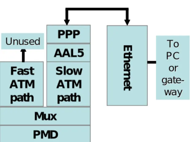
As Figure 3shows, the current typical DSL protocol stack is an outdated collection of options supporting PPP and ATM sublayers. It was built to accommodate services that were never deployed, which results in additional costs for needless provisioning, configuration, and maintenance.
PMD
AAL5
Slow
ATM
path
PPP
Mux
Fast
ATM
path
Unused UnusedEthernet
To To PC PC or or gate gate- -way wayPMD
AAL5
Slow
ATM
path
PPP
Mux
Fast
ATM
path
Unused UnusedEthernet
To To PC PC or or gate gate- -way wayTypical DSL Modem
Typical DSL Modem
Figure 3: Typical Current DSL Protocol Stack
DSL Enhancements for EFMC
By contrast, a typical IP connection (whether it carries data, voice or video) begins and ends onEthernet, so supporting ATM just leads to unnecessary complexity. Additionally, the ATM “hardware-based” implementation that was planned
to carry much higher traffic compared to the “software implementation” of IP routers, now finds
an equal rival with hardware-based Ethernet switching modules that can carry traffic in similar
rates at lower cost. As
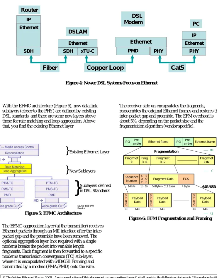
Figure 4 shows, new DSL systems will strip out the intermediate sublayers and move to native Ethernet over DSL
PMD PHY PHY xTU-C SDH ATM SDH AAL5 PPP Ethernet IP Ethernet IP
PC
PC
Router
Router
DSLAM
DSLAM
Fiber
Fiber
Copper Loop
Copper Loop
Cat5
Cat5
Ethernet Ethernet
Ethernet
Ethernet EthernetEthernet
DSL
DSL
Modem
Modem
Figure 4: Newer DSL Systems Focus on Ethernet
With the EFMC architecture (Figure 5), new data link sublayers (closer to the PHY) are defined by existing DSL standards, and there are some new layers above those for rate matching and loop aggregation. Above that, you find the existing Ethernet layer
}
New Sublayers}
Existing Ethernet Layer}
Sublayers defined in DSL StandardsSource: IEEE EFM Baseline Figure 5: EFMC Architecture
The EFMC aggregation layer (at the transmitter) receives Ethernet packets through an MII interface after the inter-packet gap and the preamble have been removed. The optional aggregation layer (not required with a single modem) breaks the packet into variable length
fragments. Each fragment is then forwarded to a specific modem's transmission convergence (TC) sub-layer, where it is encapsulated with 64B/65B Framing and transmitted by a modem (PMA/PMD) onto the wire.
The receiver side un-encapsulates the fragments, reassembles the original Ethernet frames and restores the inter-packet gap and preamble. The EFM overhead is about 5%, depending on the packet size and the fragmentation algorithm (vendor specific).
14 bits 1b 1b 64 Bytes - 512 Bytes 4 Bytes
1B 64B 1B 64B 1B 64B
Fragmentation
64B/65B
IPG
Pre-amble Ethernet frame IPG
Pre-amble Ethernet frame
Fragmnet k Frag. k+1 Fragmnet k+N Fragmnet k+2 Sequence Number S O P FCS E O P Fragment Data S Y N C Payload Data S Y N C Payload Data S Y N C Payload Data MII γ α/β
Copper Loop Issues and
Solutions
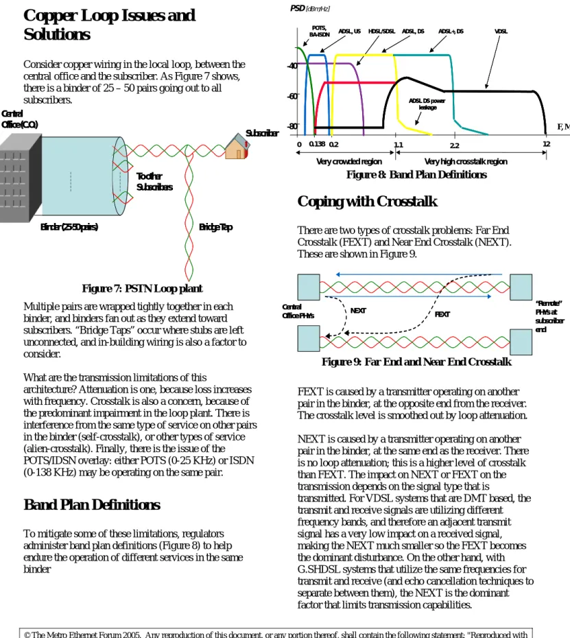
Consider copper wiring in the local loop, between the central office and the subscriber. As Figure 7 shows, there is a binder of 25 – 50 pairs going out to all subscribers. Central Office (C.O.) Subscriber Bridge Tap Binder (25-50 pairs) To other Subscribers Central Office (C.O.) Subscriber Bridge Tap Binder (25-50 pairs) To other Subscribers
Figure 7: PSTN Loop plant
Multiple pairs are wrapped tightly together in each binder, and binders fan out as they extend toward subscribers. “Bridge Taps” occur where stubs are left unconnected, and in-building wiring is also a factor to consider.
What are the transmission limitations of this
architecture? Attenuation is one, because loss increases with frequency. Crosstalk is also a concern, because of the predominant impairment in the loop plant. There is interference from the same type of service on other pairs in the binder (self-crosstalk), or other types of service (alien-crosstalk). Finally, there is the issue of the POTS/IDSN overlay: either POTS (0-25 KHz) or ISDN (0-138 KHz) may be operating on the same pair.
Band Plan Definitions
To mitigate some of these limitations, regulators administer band plan definitions (Figure 8) to help endure the operation of different services in the same binder -60 -40 PSD[dBm/Hz] 0.138 1.1 0 0.2 HDSL/SDSL HDSL/SDSL ADSL, US ADSL, US F, MHz
Very high crosstalk region
12 -80 ADSL, DS ADSL DS power leakage ADSL, DS ADSL DS power leakage ADSL DS power leakage
Very crowded region POTS,
BA-ISDN POTS,
BA-ISDN ADSL+, DSADSL+, DS
2.2
VDSL VDSL
Figure 8: Band Plan Definitions
Coping with Crosstalk
There are two types of crosstalk problems: Far End Crosstalk (FEXT) and Near End Crosstalk (NEXT). These are shown in Figure 9.
“Remote” PHYs at subscriber end Central
Office PHYs NEXT FEXT
“Remote” PHYs at subscriber end Central
Office PHYs NEXT FEXT
Figure 9: Far End and Near End Crosstalk
FEXT is caused by a transmitter operating on another pair in the binder, at the opposite end from the receiver. The crosstalk level is smoothed out by loop attenuation. NEXT is caused by a transmitter operating on another pair in the binder, at the same end as the receiver. There is no loop attenuation; this is a higher level of crosstalk than FEXT. The impact on NEXT or FEXT on the transmission depends on the signal type that is
transmitted. For VDSL systems that are DMT based, the transmit and receive signals are utilizing different frequency bands, and therefore an adjacent transmit signal has a very low impact on a received signal, making the NEXT much smaller so the FEXT becomes the dominant disturbance. On the other hand, with G.SHDSL systems that utilize the same frequencies for transmit and receive (and echo cancellation techniques to separate between them), the NEXT is the dominant factor that limits transmission capabilities.
Determining Channel Capacity
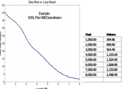
The example in Figure 10is for downstream VDSL (with Plan 998). Feet Meters 1,000.00 304.80 2,000.00 609.60 3,000.00 914.40 4,000.00 1,219.20 5,000.00 1,524.00 6,000.00 1,828.80 7,000.00 2,133.60 8,000.00 2,438.40 Feet Meters 1,000.00 304.80 2,000.00 609.60 3,000.00 914.40 4,000.00 1,219.20 5,000.00 1,524.00 6,000.00 1,828.80 7,000.00 2,133.60 8,000.00 2,438.40 Feet
Feet Meters Meters
1,000.00 1,000.00 304.80304.80 2,000.00 2,000.00 609.60609.60 3,000.00 3,000.00 914.40914.40 4,000.00 4,000.00 1,219.201,219.20 5,000.00 5,000.00 1,524.001,524.00 6,000.00 6,000.00 1,828.801,828.80 7,000.00 7,000.00 2,133.602,133.60 8,000.00 8,000.00 2,438.402,438.40 Example: VDSL Plan 998 Downstream
Figure 10: Sample Data Rate versus Loop Reach (Downstream VDSL)
Compared to normal DSL rates on the order of 384 Kbps, it’s surprising to see, for instance, that 10 Mbps is theoretically possible at a greater than 5000 foot reach. The above performance chart assumes ten self-FEXT disturbers, no self-NEXT disturbers, and a background noise of -140 dBm/Hz.
EFMC Ports: Short Reach and
Long Reach
The two EFMC port types are a short reach PHY, type 10PASS-TS and a long reach PHY, type 2BASE-TL. The bandwidth and distance capabilities of these options are shown in Figure 11.
10Pass-TS 1-pair 2Base-TL 8-pairs 2Base-TL 1-pair Ban d wi dt h Distance
Figure 11: Short and Long Reach Options for EFMC
For the short reach PHY (EFMC SR), the band plan works as follows. Plan 997 is used in Europe, and Plan 998 is used in North America. The short reach PHY details are illustrated in Figure 12.
Figure 12: EFMC Short reach PHY Details
The long reach PHY (EFMC LR) is based on the ITU-T G.991.2 standard for single-pair high-rate DSL; it is inherently symmetric and uses TC-PAM. An extended version of this line code called the G.SHDSL.bis is now being standardized by ITU-T and ANSI, and has been adopted by the EFM committee. This extended version allows bit rates of up to 5.7 Mbps symmetrical, while still complying with spectral compatibility requirements such as ANSI T1.417. The G.SHDSL.bis enables delivery of high speeds to long distances, covering almost all the customer base of the service providers.
Copper Loop Bonding
EFM has introduced an important capability to copper-based system – the ability to utilize more than one pair and carry far more bandwidth over the exiting copper infrastructure. The EFM aggregation layer allows multiple pairs to be used as a single, high capacity link, providing a “fiber replacement” in places where fiber does not exist. With loop bonding capability, no customer will be left without high-speed business-class Ethernet service, making Ethernet service ubiquitous. While some other bonding mechanisms were suggested in the past to perform this function, the EFM bonding has proven to be most efficient for delivering Ethernet traffic. Specifically designed to meet the requirements of copper transmission, with less-than-optimal
predictability and variable rates and delays on the pairs, the EFM bonding is a natural bonding scheme choice for Ethernet services. While specific vendor enhancements to the transmission layer may allow additional
performance gain, the EFM standard bonding allows for vendor interoperability and enables mass deployment. When comparing the EFM bonding to alternative bonding schemes such as inverse multiplexing over ATM (IMA), or the M-pair G.SHDSL scheme, EFM proves in to be superior in all aspects. Table 2 provides a detailed comparison.
EFM 802.3ah IMA M-pair G.SHDSL
Service
Optimization Ethernet ATM TDM
Network Integration
Ethernet/IP
native interface ATM networks
Not Defined (system feature) Service conversion required No Yes Yes Overhead ~5% ~20% in mixed traffic ~40% in short frames ~20% in mixed traffic ~40% in short frames Operates on pairs with different rates Yes (can utilize the
high and low rates)
No (uses lowest rate for all pairs)
No (uses lowest rate
for all pairs) Typical bonding delay 2-4ms 25-100ms 2-4ms Noise Immunity High-Med (depending on vendor implementation) Low (long recovery time) Low (single pair-loss
drops the link) Management complexity Low (Ethernet management) High (ATM management) Not defined in standard (system implementation)
Table 2: Copper Bonding Scheme Comparison
Conclusion
An evolution of current DSL technology is required to address business and residential growth in bandwidth demand and quality requirements. The IEEE EFMC standard codifies the efficient delivery of Ethernet packets directly over copper pairs at 10 Mbps and above in both directions. This native Ethernet solution provides a seamless integration into today’s and tomorrow’s networks.
While the initial goal is to achieve 10 Mbps at 750m (EFMC SR) and 2 Mbps at 2,700m (EFMC LR), the standard does not limit implementation to these rates and existing products already exceed them, delivering higher throughput to longer distances. Additionally, the introduction of copper bonding into the standard allows delivery of even higher bandwidth to longer distances over multiple copper pairs, enabling a good alternative in places where fiber does not exist or is not economical to deploy.
By reducing service provider capital expenditures for implementation, EFMC is an easy, low-cost, and immediate solution for providing feature-rich, high-speed access and services to subscribers. This is an attractive access solution for both residential and business users, and can coexist with ADSL, VDSL, ISDN and PSTN in the same cables, bringingnative Ethernet to the first mile over a twisted pair access network.
Appendix
Terminology
Term Definition
Ethernet A packet-based protocol that is used
universally in local area networks and strong candidate for cost efficient deployment in access and metropolitan networks. EFMC Ethernet in First Mile topology for
voice-grade copper.
EFMF Ethernet in First Mile using Point-to-Point Fiber topology
EFMP Etehrnet in First Mile using Point-to-Multipoint topology, based on Passive Optical Networks (PONs).
FTTB Fiber to the building
EMI Electro-magnetic interference FCC Federal Communications Commission FTTC Fiber to the curb
FTTH Fiber to the home First
Mile
Also called the last mile, the subscriber access network or the local loop, the first mile is the communications infrastructure of the business park or the neighborhood. IEEE Institute of Electrical and Electronics
Engineers. A standards setting body responsible for many telecom and
computing standards, including the Ethernet in the First Mile standard, IEEE 802.3ah. MDU Multi-dwelling unit, such as an apartment
house or hotel.
MTU Multi-tenant units, such as an apartment house or office building.
OAM The specification for managing EFM. Network
operator
Also called service providers and local exchange carriers, they provide access network services to subscribers.
PON Passive Optical Network. A single, shared optical fiber that has inexpensive optical splitters located near the subscribers. PMA Physical Medium Attachment sub-layer PMD Physical Medium Dependent sub-layer PHY Physical Layer
PSTN Public Switched Telephone Network.
References and Resources
Reference Description
IEEE 802.3-2002
“CSMA/CD Access Method and Physical Layer Specifications”,
http://standards.ieee.org/reading/ieee/std/lan man/restricted/802.3-2002.pdf
IEEE 802.1Q
“Virtual Bridged Local Area Networks”, http://standards.ieee.org/reading/ieee/std/lan man/802.1Q-1998.pdf
MEF 10
MEF Technical Specification “Ethernet Service Attributes, Phase 1”,
http://www.metroethernetforum.org/PDFs/S tandards/MEF10.pdf
MEN Technical Overview
“ Metro Ethernet Networks – A Technical Overview”,
http://www.metroethernetforum.org/PDFs/ WhitePapers/metro-ethernet-networks.pdf
Disclaimer
This paper reflects ongoing work within the MEF captured in a series of technical specifications which are a work in progress. The official MEF specifications are available at www.metroethernetforum.com/techspec. These represent a 75% member majority consensus as voted by members of the MEF Technical Committee at the time of their adoption.
This paper will be updated as new work emerges from the MEF Technical Committee. Updates versions are available at http://www.metroethernetforum.org .
About the Metro Ethernet Forum
The Metro Ethernet Forum (MEF) is a non-profit organization dedicated to accelerating the adoption of optical Ethernet as the technology of choice in metro networks worldwide.
The Forum is comprised of leading service providers, major incumbent local exchange carriers, top network equipment vendors and other prominent networking companies that share an interest in metro Ethernet. As of December 2005, the MEF had over 70 members