Terms and Conditions of Use of Digitised Theses from Trinity College Library Dublin
Copyright statement
All material supplied by Trinity College Library is protected by copyright (under the Copyright and Related Rights Act, 2000 as amended) and other relevant Intellectual Property Rights. By accessing and using a Digitised Thesis from Trinity College Library you acknowledge that all Intellectual Property Rights in any Works supplied are the sole and exclusive property of the copyright and/or other I PR holder. Specific copyright holders may not be explicitly identified. Use of materials from other sources within a thesis should not be construed as a claim over them.
A non-exclusive, non-transferable licence is hereby granted to those using or reproducing, in whole or in part, the material for valid purposes, providing the copyright owners are acknowledged using the normal conventions. Where specific permission to use material is required, this is identified and such permission must be sought from the copyright holder or agency cited.
Liability statement
By using a Digitised Thesis, I accept that Trinity College Dublin bears no legal responsibility for the accuracy, legality or comprehensiveness of materials contained within the thesis, and that Trinity College Dublin accepts no liability for indirect, consequential, or incidental, damages or losses arising from use of the thesis for whatever reason. Information located in a thesis may be subject to specific use constraints, details of which may not be explicitly described. It is the responsibility of potential and actual users to be aware of such constraints and to abide by them. By making use of material from a digitised thesis, you accept these copyright and disclaimer provisions. Where it is brought to the attention of Trinity College Library that there may be a breach of copyright or other restraint, it is the policy to withdraw or take down access to a thesis while the issue is being resolved.
Access Agreement
By using a Digitised Thesis from Trinity College Library you are bound by the following Terms & Conditions. Please read them carefully.
E x p lo itin g C o m m o d ity P a ra llel H ard w are for
C o m p u ter G rap h ics A p p lic a tio n s and
A r c h ite c tu r e s
A Thesis
Subniitted to th e Office of G raduate Studies
of
University of DubUn, Trinity College
in Candidacy for th e Degree of
D octor of Philosophy
by K eith O ’Conor
D ecla ra tio n
I, th e undersigned, declare th a t this work has not previously been subm itted as
an exercise for a degree a t this, or any other University, and th a t unless otherwise
stated, is my own work. This thesis may be borrowed or copied upon request with
th e permission of the Librarian, Trinity College, University of Dublin. The copyright
belongs jointly to th e University of Dublin and K eith O ’Conor.
Keith O 'Conor
A cknow ledgm ents
F irst and foremost, my sincerest thanks to my supervisor Carol O'Sullivan. Carol
has never been anything less th a n enthusiastic and supportive of all my endeavours
here at the ISG, and I would not be where I am to d ay w ithout her.
The ISG has been a great place to w'ork and live over th e last four years. The
people I have m et here have become good friends, and I will not soon forget them.
My th an k s go to John Dingliana for taking on th e final year project th a t led to
my position in the ISG. T hanks also to Simon for the engaging work we have done
together, and for all th e entertaining chats ab o u t everything from graphics to jazz.
I also owe a big thanks to Andrew Brosnan for his late-night proofreading during
the final crunch.
To my parents and my brother Hugh who have always believed in me, even when
I d id n ’t believe in myself. They are a constant source of encoiuagem ent, strength
and inspiration.
Finally, to my friend and my love, Elaine. She makes it all worthwhile.
K e i t h O ’C o n o r
Isosurface E xtraction on th e Cell P rocessor
K. O ’Conor, C. O ’Sulhvan and S. Collins.
Proceedings of Eurographics Ireland Workshop, October 2006
A Scalable and R econfigurable Shared-M em ory G raphics A rch itectu re
M. Manzke, R. Brennan, K. O ’Couor, J. Dingliana and C. O ’Sullivan.
Proceedings of ACM SIGGRAPH 2006 Sketches &; Applications, 2006, p. 182
G eopostors: A R eal-T im e G e o m e tr y /Im p o sto r Crowd R en dering S ystem
S. Dobbyn, J. Hamill, K. O ’Conor and C. O ’Sullivan.
ACM Transactions on Graphics, 24(3), 2005
G eopostors: A R eal-T im e G e o m e tr y /Im p o sto r Crowd R en dering S ystem
S. Dobbyn, J. Hamill, K. O ’Conor and C. O ’Sullivan.
Proceedings of ACM SIGGRAPH Symposium on Interactive 3D Graphics and Games
2005, pp. 95 - 102
P ercep tu a lly A d a p tiv e G raphics
C. O'Sullivan, S. Howlett, Y. Morvan, R. McDonnell and K. O ’Conor.
Eurographics State of the Art reports, September 2004. pp. 141-164. Also to appear
in Computer Graphics Forum.
3D V isu alisation o f C onfocal F lu orescen ce M icroscopy D ata
K. O ’Conor, H.P. Voorheis and C. O ’Sullivan.
A b stract
The processing power available in to d a y ’s com m odity parallel hardw are has en abled realism and detail in graphics th a t has never before been possible. W ith th e
advent of th e progrannnable G raphics Processor U nit (G PU ), th e full potential of parallel architectures to accelerate graphics algorithm s has become apparent. This parallelism is becoming more ubiquitous in other processors, and research th a t ex ploits this parallelism is ongoing.
In this thesis we apply th e knowledge learned of rendering clusters to th e design of a new tightly-coupled cluster architecture for parallel rendering, and describe a software infrastructure for im plem enting distributed rendering by taking advantage of th e unique mix of parallel hardw are available. We then concentrate on th e ap plication of this com m odity parallel hardw are to two im p o rtan t fields of com puter graphics api)lications; scientific visualisation and entertainm ent.
Under scientific visualisation, we describe the use of th e program m able pipeline for direct volume rendering of datasets captured by confocal fluorescence microscopy, as well as introducing a simple m ethod for fast volvmietric simplification which al lows broad feature preservation while allowing faster isosurface extraction and noise reduction when applied to confocal datasets. We also introduce a novel algorithm for perform ing isosurface extraction on Cell, th e recently developed high-profile mul ticore processor from IBM, Sony and Toshiba. We give an overview' of the processor and detail how to exploit it for algorithm ic acceleration.
C h a p ter 1 I n tr o d u c tio n 1
1.1 P a ra lle lis m ... 2
1.2 C ontext and S c o p e ... 3
1.3 C o n tr ib u tio n s ... 4
1.4 Sum m ary of C hapters ... 5
C h a p ter 2 B a ck g ro u n d and R e la te d W ork 6 2.1 G raphics H a r d w a r e ... 6
2.1.1 H ardw are A c c e le ra tio n ... 7
2.1.2 Em barrassingly Parallel ... 7
2.1.3 T he Graphics P i p e l i n e ... 9
2.1.4 Exploiting Graphics H a rd w a re ... 14
2.1.5 B o t t l e n e c k s ... 15
2.2 Com m odity C l u s t e r s ... 17
2.2.1 Using com modity p a r t s ... 17
2.2.2 Parallel Rendering on C lu s te r s ... 17
2.2.3 R elated W o r k ... 19
2.3 Field Program m able G ate A r r a y s ... 20
2.3.1 B a c k g r o u n d ... 20
2.3.2 A d v a n t a g e s ... 21
2.3.3 D isa d v a n ta g e s... 21
2.3.4 FP G A s and G ra p h ic s ... 22
2.4 The Cell B roadband E n g i n e ... 23
2.4.2 A rc h ite c tu r e ...24
2.4.3 Program m ing Cell ... 27
2.4.4 Cell-Related Research ...29
C h a p ter 3 T ow ards a N e w F ram ew ork 31 3.1 Proposed C l u s t e r ... 32
3.1.1 Cluster O v e r v ie w ...33
3.1.2 Scalable Coherent Interface ... 36
3.1.3 D istributed Shared M e m o r y ... 38
3.1.4 A i m s ... 39
3.2 G raphics H a r d w a r e ... 40
3.2.1 Graphics D r i v e r s ...40
3.2.2 Hardware R e g is te r s ... 43
3.2.3 T he AGP A p e r t u r e ... 44
3.2.4 Employing Hardware A c ce le ratio n ... 45
3.3 Software I n f r a s tr u c tu r e ... 49
3.3.1 M olnar’s Taxonomies R e v i s i t e d ...49
3.3.2 W orkstation Parallelism ... 51
3.3.3 Connnunicating w ith the D r i v e r ... 52
3.3.4 Connnunicating w ith the FPG A C o-i)rocessors... 54
3.4 Com parison w ith the Cell P r o c e s s o r... 55
3.5 Exam ple Applications ... 57
C h a p ter 4 S cien tific V isu a lisa tio n 60 4.1 Volume V is u a lis a tio n ... 61
4.1.1 Direct Volume R e n d e rin g ... 61
4.1.2 Volume Rendering on Com m odity Graphics H a rd w a re 64 4.1.3 Isosurface E x t r a c t i o n ... 67
4.1.4 Accelerating Isosurface E x tr a c tio n ... 70
4.1.5 Isoextraction on G raphics Hardware ... 71
4.2 Accelerated Visualisation w ith Parallel Hardware ... 73
4.2.1 Confocal Fluorescence M icro sco p y ... 73
4.4 Isosurface E xtraction on th e Cell P ro c e s s o r... 80
4.4.1 Cell A pplicability to M arching T e t r a h e d r a ... 81
4.4.2 Im p le m e n ta tio n ... 81
4.4.3 Volume Partitioning ... 82
4.4.4 D ata t r a n s f e r ... 82
4.4.5 P ro c e s s in g ... 84
4.5 R e s u lts ... 85
4.5.1 Isosurface S im p lific a tio n ... 85
4.5.2 Cell Is o e x tra c tio n ... 90
4.6 C luster Im plem entation ... 95
4.6.1 Volume V is u a lis a tio n ... 95
4.6.2 Volume Simplification ... 96
4.6.3 Isosurface E x t r a c tio n ... 97
C h a p t e r 5 E n t e r t a i n m e n t 98 5.1 Parallel Hardware in E ntertainm ent A pplications ... 99
5.1.1 G raphics Hardware in G a m e s ... 99
5.1.2 Crowd R e n d e r in g ... 100
5.1.3 Reducing Rendering W o r k ...102
5.1.4 A Further Level of Detail; I m p o s t o r s ...103
5.1.5 Hardware Implications of Im postor Usage ...106
5.1.6 Introducing V a ria tio n ... 107
5.1.7 Dynamic Im postor L i g h t i n g ... 109
5.2 Accelerating Crowd R e n d e rin g ...110
5.2.1 Disadvantages of M ulti-pass Algorithm s ... I l l 5.2.2 Dynamic Im postor L i g h t i n g ... 112
5.2.3 Im postor V a r i a t i o n ... 114
5.2.4 A uthoring O u tf it s ...116
5.3 R e s u lts ... 117
C h a p ter 6 C o n c lu sio n s an d F u tu r e W ork 121
6.1 Summary of C o n trib u tio n s ... 121
6.2 Future W o rk ... 123
6.2.1 Isosurface Extraction and Volumetric Sim plification... 123
6.2.2 Parallel Commodity C l u s t e r ...124
2.1 The G raphics P i p e h n e ... 10
2.2 Cell Processor O v e r v ie w ... 24
2.3 The PowerPC Processor Element (P P E ) ... 25
2.4 The Synergistic Processor Element (SPE) ... 27
2.5 Cell program m ing models ... 28
3.1 A custom board w ith graphics card and SCI Link Controllers . . . . 34
3.2 A cluster node w ith attached SCI PC I card ... 35
3.3 An overview of the proposed cluster ... 37
3.4 D istributed Shared Memory implemented in hardware ... 39
3.5 Photo of the first prototype custom b o a r d ... 40
4.1 Evident proxy geometry in 2D texture-based volume rendering . . . . 66
4.2 The 14 possible cases of Marching C u b e s ... 69
4.3 Decomposition of a cube and triangulation in Marching T etrahedra . 70 4.4 Cross-eyed stereo and DVR screenshot of Trypanosoma Brucei . . . . 74
4.5 Inserting interpolated slices ... 76
4.6 DVR and corresponding extracted isosurfaces ... 77
4.7 Volumetric simplification of the Head Aneurysm dataset ...78
4.8 Volumetric simplification of the C hrom atid Separation d ataset . . . . 79
4.9 Volume slice divided into chunks for distribution to 4 S P U s ... 83
4.10 Trypanosom a Brucei # 1 s im p lif ic a tio n ... 87
4.11 Trypanosom a Brucei # 2 s im p lif ic a tio n ... 87
4.12 C hrom atid separation sim p lific a tio n ... 88
4.13 Bonsai Tree s im p lif ic a tio n ... 88
4.15 T ry p an o so m a B rucei 7^2 sim plification s c r e e n s h o ts ... 89
4.16 C h ro m a tid S ep aratio n sim plification s c r e e n s h o ts ... 89
4.17 B onsai Tree sim plification s c r e e n s h o ts ... 89
4.18 S pherical shell volum e afte r isoex tractio n on Cell ... 91
4.19 B onsai Tree volum e afte r iso ex tractio n on C e l l ... 91
4.20 T est resu lts for th e 1024^ a n d 512^ spherical shell volum es ... 92
4.21 T est resu lts for th e 256^ a n d 128^ spherical shell v o l u m e s ... 92
4.22 T est resu lts for th e 64^ a n d 32^ spherical shell v o l u m e s ... 93
4.23 T est resu lts for th e B onsai Tree a n d H ead A neurysm volum es . . . . 93
4.24 Isosurface e x tra c tio n s p e e d s ... 94
5.1 N orm al m a p p in g in th e Unreal 5 e n g i n e ... 101
5.2 D eserted streets in GTA: San A nd reas ... 102
5.3 Im p o sto r view points ... 105
5.4 U nconvincing c r o w d s ... 107
5.5 Lack of crow d v ariatio n in F ight N ight R ound 3 ...108
5.6 A n im p o sto r norm al nrap for a single fram e of a n i m a t i o n ... 110
5.7 T e x tu re i n d i r e c t i o n ...114
5.8 T h e single-pass im p o sto r sh ad in g an d colouring process ... 115
5.9 T h e o u tfit to o l used for choosing im p o sto r colour m a p s ... 117
AGP
Accelerated G raphics PortAPI
Application Program m ing InterfaceAR B
O penG L’s A rchitecture Review BoardASIC
Application-Specific Integrated C ircuitB A R
Base Address RegistersBEI
Broadband Engine InterfaceCBE
Cell B roadband EngineCOTS
Com m odity Off-The-ShelfCP
Conunand ProcessorC P U
C entral Processing LhiitCT
Com puterised Tom ographyDLL
Dynamic Link LibraryDM A
Direct Memory AccessDSM
D istributed Shared M emoryDVI
Digital Visual InterfaceD V R
Direct Volume RenderingEIB
Element Interconnect BusFIFO
F irst In F irst OutFPG A
Field Program m able G ate ArrayCART
Graphics Address R em apping TableGLSL
OpenGL Shading LanguageG P G P U
G eneral-Purpose C om putation on G PUsG PU
Graphics Processing UnitIB R
Image Based RenderingLC
Link ControllerLOD
Level Of D etailLRU
Least Recently UsedMFC
M emory Flow ControllerMIC
M emory Interface ControllerM IM D
M ultiple Instructions M ultiple D a taMMIO
M emory M apped In p u t/O u tp u tM PI
Message Passing InterfaceMRI
M agnetic Resonance ImagingM T
M arching T etrah ed raN U M A
Non-Uniform M emory AccessPCI
Peripheral C om ponent InterconnectPIO
Program m ed In p u t/O u tp u tPLD
Program m able Logic DeviceP P E
PowerPC Processor ElementP P U
PowerPC Processor UnitPSGL
Playstation G raphics LanguageP V M
Parallel V irtual MachineRISC
Reduced Instruction Set C om puterSCI
Scalable C oherent InterfaceIn trod u ction
Since th e introduction of th e m odern integrated circuit com puting power has been increasing rapidly due to improvements in technology and m anufacturing m ethods. Furtherm ore, this power does not come a t a com m ensurate price. Q uite th e opposite is true; in 1997 the equivalent price of one gigaflop of power was $30,000 [140]. Today in 2006, th a t price has dropped to under $1 in th e case of th e most recent G raphics Processor U nits (GPUs).
The widespread availability and low price of com puting power has been the cause of a m ajor boom in personal com puting and th e consequent uljiquity of desktop w orkstations seen today. Even a m oderate desktop com puter is now capable of billions of floating point operations per second - orders of m agnitude faster th a n a machine th a t would have been term ed a ‘supercom puter’ 30 years ago. The low cost of this hardw are enables ordinary com m odity off-the-shelf (CO TS) systems to perform complex sim ulations in real-tim e a t interactive rates to a degree th a t was never before possible w ithout extrem ely expensive hardw are or dedicated custom architectures.
1.1 P a r a lle lism
mviltiple processors an d ta k e a d v an tag e of th e in herently parallel n a tu re of m any algo rithm s.
1.1
P a r a lle lism
T h e key concept of p arallel c o m p u tin g is th e decom position of a problem into d iscrete co m p o n en ts th a t can be solved individually. T h is can be carried o u t in tw o form s, classified by w here in th e sy stem th e parallelism is im plem ented.
Im plicit parallelism , w here th e system a u to m a tic a lly p a rtitio n s w ork to b e dis trib u te d am ong processors, can b e seen in system s such as th e G P U p ip elin e an d ce rta in S IM D -optim ising com pilers. In th is case th e developer does n o t need to spec ify any d etails of how work will b e segm ented. However, for p erform an ce-oriented ap p licatio n s it still helps to ta k e it into con sid eratio n a t th e design stage, in order to allow th e work to be parallelised as efficiently as possible.
O n th e o th e r h an d , explicit parallelism can be seen in areas such as m u lti th re a d e d ap p licatio n s or d is trib u te d system s. In th is case, developers nn ist specifi cally design th e a p p licatio n a ro u n d th e d istrib u tio n m odel, tak in g in to accou nt all th e perfo rm an ce im plication s a n d com m unication restrictio n s th a t acco m pan y th e un derly ing arc h ite c tu re in o rd er to perfo rm th e maximvun am oim t of c o m p u ta tio n a t any stage.
1.2
C o n tex t and Scope
T he work contained in this thesis began as p a rt of a HEA-funded project; the In stitu te for Inform ation Technology and Advanced C om putation (IITAC), w ith the a u th o r’s particu lar rem it being to study cluster-based rendering frameworks (such as C hrom ium - see Section 2.2.3) and their use for scientific visualisation. Specifically,
the stu d y of th e protozoa Trypanosom a Brucei was to be the subject of visualisation in association w ith th e Cell M embrane G roup in Trinity College Dublin. Interactive visualisation necessitated the investigation of program m able graphics hardw are in order to allow real-tim e rendering of th e d atasets being captured by the confocal microscopes used to study this organism.
W hile this research was being carried out, it was recognised th a t work being carried ou t by others on th e sam e project, on crowds and virtual hum an rendering, could benefit greatly from th e knowledge gained of graphics hardware. This was applied to accelerate crowd rendering and enable large num bers of hum ans to be sim ulated in real-time.
From this earlier work, a new project arose in association w ith the C om puter A rchitecture G roup (CAG) and funded by Science Foundation Ireland (SFI). This project aim s to build upon the knowledge of clusters and connnodity graphics hard ware gained in the previous research to produce a new hardw are framework th a t incorporates th e advantages of b o th architectures. It also encompasses knowledge gained by researchers in th e CAG in relevant areas such as Field Program m able G ate A rrays and the Scalable Coherent Interconnect in order to produce a new parallel cluster architecture for distrib uted rendering and simulation. The a u th o r’s p articu lar rem it in this project was the investigation of the required software infras tru c tu re and th e exploitation of th e framework for different types of applications, in p articular, entertainm ent and scientific visualisation.
Most recently, an oppo rtu n ity arose to investigate th e application of the new Cell processor for accelerating graphics algorithm s. From the experience gained in both volume visualisation of microscopy d a ta and th e use of parallel graphics hardware, it was recognised th a t this new parallel architecture could be used to substantially accelerate th e area of surface extraction, necessary for isolating particular structures
1.3 C o n tr ib u tio n s
Therefore, th e following chapters present th e research perform ed in these projects. Specifically, th e parallel architectures th a t were used and their application to the areas of scientific visualisation (volume rendering and surface extraction) and enter tainm ent (crowd and virtual hum an rendering).
1.3
C on tribu tion s
In this thesis, we will look at how b o th implicit and explicit parallel system s can be employed in order to accelerate existing graphics algorithm s. The m ajor contribu tions are as follows:
• An overview of a variety of parallel architectures including bo th distributed system s and parallel processors. We investigate their exploitation for acceler ating graphics algorithm s and discuss their use in j)revious research.
• Details of a new hardw are cluster for accelerating distributed rendering. We describe th e low-level mechanism of existing graphics drivers and outline a so ftw a re in fra str u c tu re to exploit th e uniciue assortm ent of heterogeneous parallel hardw are in th e cluster to provide acceleration of bo th sinuilation and rendering algorithms.
• The use of the program m able pipeline for d ir e ct v o lu m e r en d e rin g of d atasets captured by confocal fluorescence microscopy. W'e also introduce a simple m ethod for quick v o lu m e tr ic sim p lific a tio n which allows broad feature preservation while allowing faster isosurface extraction and noise re duction when applied to confocal datasets.
• The use of the programmable graphics pipeline to accelerate and improve the rendering of im p ostor-b ased crowds made up of a large number of virtual humans. We discuss the shortcomings of previous methods when applied to state of the art graphics hardw^are and detail a new algorithm th at can be applied to achieve superior results.
1.4
Sum m ary o f C hapters
The rest of this thesis is divided up into the following chapters:
C h ap ter 2 describes the different parallel architectures w'e will be exploring through out the rest of the thesis; GPUs, commodity clusters, FPGAs and the Cell Broadband Engine. Related research in each area is also presented, with a particular focus on their applications to graphical algorithms.
C h ap ter 3 presents a new hardware framework built at Trinity College Dublin in association with the Computer Architecture Group. We describe the under lying architecture, composed of custom-built FPGA-based boards attached to commodity graphics cards and connected by an SCI interconnect with dis tributed shared memory. We also discuss the inner workings of a graphics driver based on technical specifications supplied by ATI, and propose a suit able software infrastructure for exploiting such an architecture.
C h ap ter 4 explores the area of scientific visualisation. We give an overview of volume rendering, both direct and indirect, before describing the contributing work of this thesis in the areas of volume rendering, volumetric simplification and isosurface extraction on commodity parallel hardware.
C h ap ter 5 details the use of commodity parallel hardware in the field of entertain ment applications. We concentrate on crowd rendering, exploring previous m ethods and describing an algorithm for producing hardware-optimal lit and varied humans th at can be used in a hybrid im postor/geom etry crowd system.
C hapter 2
Background and R ela ted W ork
There are m any different levels of parallel architectures. Some exhibit parallelism by distributing work to discrete com ponents of th e system. O thers employ internal par allelism; th e job is broken up into steps to be processed sim ultaneously in a pij^elined fashion. However, all architectures are advancing rapidly due to improvem ents in design and m anufacturing m ethods.
This chapter looks a t four distinct parallel hardw are architectures, including distrib u ted cluster system s and parallel chips. It gives an overview of each and details previous research perform ed w ith each architecture in relation to graphics algorithm s.
2.1
G ra p h ics H ard w are
2.1.1
H ardw are A ccelera tio n
3D graphics acceleration through dedicated com m odity hardw are is not a new topic. T he first generation of affordable com m odity 3D accelerator cards arrived in 1996 w ith the widespread adoption of SDfx’s Voodoo range of expansion cards. W hen the price of mem ory dropped substantially in the same year, these cards could finally be m anufactured and sold a t affordable prices. Soon com petitors such as ATI and NVIDIA were producing similar products. W ith upwards of 4MB of video memory, these cards were able to take over rasterisation from th e CPU , allowing 16-bit frame buffers and depth buffers. Soon afterw ards they were also perform ing hardw are prim itive assembly, given transform ed vertices by th e CPU.
More im portantly, they perform ed tex tu re m apping and tex tu re filtering. These operations w'ere severely lim ited in software im plem entations th a t required real-tim e frame rates, because of th e large am ount of processing and bandw idth required to filter and project a tex tu re of reasonable size in 3D. Tlie improvements in image quality and rendering speed given by these cards were im m ediately apparent and 3D graphics liardware was soon a prerequisite for m any games and other 3D appli cations.
After texturing and rasterisation, th e next step in hardw are acceleration was to perform vertex transform ation, clipping and lighting (TCL). N V ID IA ’s GeForce range was the first to introduce this feature, thus moving all of the graphics pipeline (see Section 2.1.3) processing into hardware. This relegated th e C PU to the role of subm itting vertex and tex tu re d a ta to th e G PU , freeing more CPU cycles to devote to application areas th a t are non-specific to graphics, such as physics, artificial in telligence, scene graph m anagem ent etc. Initially there was some concern over the advantages of hardw are TCL, due to benchm ark perform ances being well below th a t of software C PU perform ance. However, as hardw are improved and mesh sizes cor respondingly increased, full utilisation of hardw are TCL yielded b e tte r performance th a n equivalent software im plem entations ever could.
2.1.2
E m b arrassin gly P arallel
2.1 G ra p h ics H ard w are
to the rate of increase in circuit complexity versus size and cost, computing power doubles roughly every 18 months^. Correspondingly, GPU speeds double roughly every six months. This is due to a combination of increasingly better manufacturing processes, 3D-specific algorithmic advances, but most importantly the nature of the computations taking place.
In parallel computing terms, 3D graphics rendering is an embarrassingly parallel problem. In other words, it is a problem th at can be easily divided into many steps, each step having little or no effect on the computation of other steps. These steps can therefore Ije worked on in parallel, the results being combined to form the solution. The GPU exploits this parallelism in acting as a stream processor [139], A stream processor operates by scatter/gather; d ata is gathered from disparate sources (usually random or sequential blocks of memory), fed through one or more computational kernels and then scattered back to memory. Each kernel performs the same operation on every part of the stream th at passes through it. In the case of the GPU, the kernels are the vertex processor and the pixel processor, as described in Section 2.1.3.
In comparing this to a CPU ’s need to perform every instruction in sequential order, we get an insight into why the GPU can greatly out-perform the general purpose processor - even ignoring the obvious speed advantages of parallel processing over serial processing. Pushing CPU speeds higher and higher places a strain on the speed at which memory can be accessed, as advances in memory latency have not been in keeping with those of the CPU for a long time [145]. The fact th at every instruction and piece of d ata must share the same path to memory exacerbates the problem. To alleviate this growling speed/latency gap, the CPU needs to devote larger amounts of chip area to cache, to the point th a t the Pentium 4 actually contains more cache than it does logic.
On the other hand, the nature of the GPU allows many operations to happen in parallel, each coming from a dedicated path in the stream and leaving via another dedicated path - in many cases (texture lookups being the obvious exception) these operations need little or no memory access. Cache can therefore be kept to a
mum; even on the latest GPUs, the texture cache is no more than a few kilobytes. Thus with less cache, more chip area can be devoted to processing and the efficiency of the entire chip increases as a result.
The latest graphics chip currently on offer is ATI’s R580, which powers the X I900 XTX boards and is comprised of 8 vertex pipelines and 48 pixel pipelines. The general trend is for games and applications to perform much more computation on fragments than on vertices, hence the imbalance. This allows unprecedented rendering parallelism and results in a theoretical peak of 10.4 gigapixels per second.
2.1 .3
T h e G raphics P ip e h n e
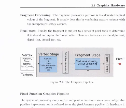
The graphics pipeline is the process th at every polygon goes through to become a pixel or group of pixels in the frame buffer (see Figure 2.1). It is broken down into the following categories:
V e rte x P ro c e ss in g : Given a model-space vertex as an input, the vertex processor applies m atrix transformations in order to output a screen-space vertex. If performing per-vertex lighting, the vertex processor is responsible for evalu ating the lighting equation at each vertex. It also performs ])er-vertex colour application and any necessary normal transform ation or texture coordinate generation.
P r im itiv e A ssem b ly : Each vertex sent through the vertex processor also has an edge flag associated with it. These edge flags specify which polygon the ver tex belongs to and describe its connectivity with the other vertices of th at polygon. From these parameters a polygon is constructed and forwarded for rasterisation.
2.1 G ra p h ics H a rd w a re
F ra g m en t P r o c e ssin g : The fragment processor’s purpose is to calculate th e final colour of th e fragm ent. It usually does this by combining tex tu re lookups w ith th e interpolated vertex colours.
P ix e l te s ts: Finally, th e fragm ent is subject to a series of pixel tests to determ ine if it should end up in the frame buffer. These are tests such as th e alpha test, depth test, stencil test etc.
Vertex
Pixel!
- mTextures
cr a . P osition ,C olor, Norm al Tex C oords,
T ex tu re A dd ressin g C olou r C om bining
etc Model Transform ations, Lighting etc Camera
Vertex Stage
Fragment Stage
Figure 2.1: The G raphics Pipeline
F ix e d F u n c tio n G ra p h ics P ip e lin e
The system of processing every vertex and pixel in hardw are via a non-configurable pipeline im plem entation is referred to as th e fixed function pipeline. In hardw are it is more efficient to implem ent and easier to optim ise a pipeline of specific operations in a specific order th a n it is to im plem ent generalised logic. This was originally th e way graphics hardw are was able to achieve sufficient 3D acceleration.
[image:26.551.18.531.69.507.2]A rchitecture Review Board (ARB). On the other hand, Microsoft has com plete au tonom y in deciding which features get included in DirectSD. This results in more regular DirectSD releases, usually accompanying th e release of a new graphics card generation. In any case th e underlying hardw are functionality is always th e same, it is ju st exposed differently by th e two APIs.
In th e case of th e core OpenGL graphics A PI up until version 1.5 [119], th e fixed function pipeline was th e only option for rendering w ith hardw are acceleration. It was essentially a black box - it had various param eters to alter properties like transform ations, m aterials and tex tu re attrib u tes, b u t how these properties were applied to the scene for rasterisation was set in hardw are and could not be altered.
In th e fixed function vertex processor, the only option for lighting was to use B linn-Phong lighting [10] combined w ith G ouraud shading [44]. This model played to th e strengths of the hardw are - only evaluating the lighting equation at each vertex and using the fast hardw are interpolation needed to colour each point on the surface. D espite this m ethod missing specular highlights on low-tesselated models, this was an acceptable model for m ost 3D applications. Similarly, the fixed function fragm ent processor only allowed lim ited m ethods of tex tu re lookups, a fixed set of blending modes and no interaction w ith th e depth buffer.
The result of a single unalterable rendering equation was th a t every rendered scene always had the same lighting and th e sam e feel to it. It did not allow for variation in th e projection of vertices, nor did it give th e developer much control of tex tu re addressing or m aterial application, beyond th e limited param eters of th e OpenGL rendering equation. For this reason, th e fixed function processors were discarded and replaced w ith new program m able engines once G PU s becam e powerful enough.
P r o g r a m m a b le P ip e lin e
The switch to th e program m able graphics pipeline was a gradual one. C ards did not suddenly change from having fixed function processors to progranm iable ones, b u t rath er th e changes came in increments.
2.1 G ra p h ics H a rd w a re
the GeForce 256 also had th e first im plem entation of w hat NVIDIA called register combiners [123]. Register combiners were to be th e first step tow ards generalising the fragm ent processing stage, allowing a program m able process to decide th e final colour of a pixel. They consisted of a chain of 4-input combiner imits, each combiner being able to perform operations such as m ultiplication, addition or dot products on th e d a ta being passed through. Additionally, a final combiner could perform interpolation on the o u tp u ts of th e previous stages. The power of register combiners came from th eir configurability - th e input of any combiner could be the o u tp u t of any earlier combiner in th e chain. W hile the num ber and n atu re of th e operations were restrictive, it still allowed a great flexibility on how colours and tex tu res could be combined to produce a fragm ent.
Soon afterw ards NVIDIA produced texture shaders [33], a superset of conven tional O penG L te x tu re operations which were to supplem ent th e register combiners by adding ex tra textm 'e addressing operations. In addition to th e regular ID , 2D and 3D tex tu re addressing available in OpenGL 1.2.1 (the latest version at th e tim e), tex tu re shaders added cube m apping, dependent texturing, offset tex tu rin g and dot product texturing. Together w ith th e register combiners, tex tu re shaders allowed the fragm ent processing stage to be much more flexible th a n the core O penG L spec ification allowed.
The corresponding extension for the fragment processor was the fragment pro gram [56]. In a similar fashion to the vertex program , th e fragment program w^as a set of assembly language instructions w’hich was given complete control of th e fragm ent processing stage in order to w rite th e final colour of the fragment being processed. A ttrib u tes from the vertex processor which were interpolated by th e rasteriser are passed into th e fragm ent program as param eters.
Shader development was not easy given the assembly language interface to ver tex and fragm ent programs. Any shader of even m oderate complexity w^as hard to read and even harder to debug, and any m odularity th a t might help code reuse was difficult to m aintain. For these reasons it w^as not long before high level shad ing languages were designed; the OpenGL Shading Language (GLSL) [68] and for DirectSD th e High Level Shading Language (HLSL). These are high level shading languages, bo th loosely based on th e syntax of th e C program m ing language w ith ex tra vector types to take into account the vector-based n atu re of the imderlying hardware. The driver then compiles these shading languages into hardw are calls suitable to th e hardw are th a t the application is being run on. NVIDIA has also de veloped another shading language called Cg [98, 40]. Cg aims to overcome the A PI differences liy building a shading language on to p of b o th OpenGL and DirectSD. A program w ritten in Cg can be compiled to ta rg e t a specific platform , such as the com bination of a particular G PU w ith a particu lar A PI. It then produces code th a t will work correctly on th a t platform . Cg was particvilarly useful wdien it was th e only other option to assembly language shader program s. Although this aspect of C g’s utility has been overshadowed by the appearance of GLSL and HLSL, it is still highly successful for cross-API shader program m ing, and keeps up w ith the latest G PU developments through support from NVIDIA. It should also be noted th a t the API for the Playstation 3’s graphics chip (the R SX , produced by NVIDIA) is PSGL, a conglomeration of extended OpenGL-ES 1.0 and Cg for shader functionality.
In more recent GPUs, the hardw are im plem entation of th e fixed function pipeline has been replaced completely by th e program m able pipeline. Any fixed function calls m ade by an application will be em ulated in shader hardw are by th e program m able processors.
2.1 G ra p h ics H a rd w a re
th e vertex processor and fragm ent processor, and will run a shader program on a per-prim itive basis. Unlike th e vertex processor it will allow the creation of new vertices and have access to both prim itive type and vertex adjacency information. Additionally, it will be possible to recirculate the newly created prim itives to the beginning of th e pipeline so th a t they can be operated on by th e vertex processor. This will allow a new class of G PU -based algorithm to be implem ented, such as procedurally created geom etry which can be transform ed by th e vertex shader and lit - all while never having to pass across the bus to th e CPU. W hen th e underlying hardw are im plem entation of this new concept is produced, it will also be exposed via th e OpenGL extension mechanism.
2.1 .4
E x p lo itin g G rap h ics H ardw are
The impressive parallel processing power offered by recent GPUs, combined with this general level of program m ability, has resulted in much research into using the G PU not ju st as a 3D accelerator bu t as a general processor for suitably parallelisable algorithms. Termed G P G P U [47] by M ark H arris [55], this model expands upon the stream -based n atu re of the G PU s to replace th e 3D processing kernel usually implemented in th e progrannnable processors w ith a kernel for general com putation, specific to th e problem dom ain to which it is applied.
These kernels use tex tu re maps as g ath er memory and th e fram e buffer as scatter memory. By employing render-to-texture m ethods, this memory can be used as a feedback input to th e same or different kernels. G PG PU applications typically perform much of th eir com putation in th e fragm ent processor, as this is where the hardw are affords th e m ost parallelism - th e com putational kernel will be executed for every pixel in the o u tp u t frame buffer. These o u tp u t values m ight be th e desired final result, or they may be stored and reused for additional com putation.
re-cently an n o u n ce d th e im p lem en tatio n of a physics sy stem im plem ented en tirely on th e G P U , n am ed Havok FX. T his fram ew ork allows for th o u sa n d s of p article s an d rigid bod ies to be sim ulated in real-tim e for special effects purposes.
2.1.5
B o ttle n e c k s
T h e pip elin ed n a tu re of graphics h ard w are has th e in h eren t im p lication th a t th e en tire sy stem can only proceed a t th e speed of its slowest section. T h e vertex tra n s fo rm a tio n stag e of a p a rtic u la r ap p licatio n m ay be very fast, b u t if an extrem ely long sh ad er p ro g ram is causing th e fragm ent processor to struggle, any speed-ups gained in th e v ertex stag e is lost. In optim isin g G P U -accelerated ap p licatio n s, th e biggest gains will be m ade by identifying an d increasing th e speed of th e slowest stage. A ny o th e r o p tim isatio n s will n o t move th e b o ttlen ec k an d con sequently will no t m ake a difference to th e a p p lic a tio n 's perform ance.
P ip e lin e B o ttle n e c k s
T h e m ost com m on b o ttlen eck in th e grap hics pipeline is eith er th e vertex stag e or th e frag m en t stage; th e p rim itive assem bly and raste risa tio n stages are rarely th e cause of a d rop in fram e rates. T h e n a tu re of a pip eline b o ttlen eck is entirely ap p licatio n -d ep en d e n t. In th e case of a sim ple m odel viewer th a t applies a single te x tu re to a very highly tessellated m odel, th e pipeline will b e slowest in th e vertex tra n sfo rm a tio n stage. Similarly, a m odel viewer th a t views only low -polygon m odels b u t applies m any com plex per-pixel effects to th e m o d e l’s sm’face will b e b o u n d by th e speed of th e fragm ent processor.
Some ap p licatio n s are n o t lim ited by any pipeline stage; in stead it is th e sub m ission of d a t a in th e first place th a t can n o t keep up w ith th e G P U ’s speed.
T ransfer B o ttle n e c k s
T h e com plexity of th e o p eratio n s perform ed by c u rren t graph ics cards necessitates th e tra n s fe r of a large am o u n t of d a ta to th e G P U for b o th geom etry an d tex tu res.
2.1 G ra p h ics H a rd w a re
bus being th e Accelerated G raphics Port (AGP). A G P is a dedicated bus based upon th e PC I specifications and specifically designed for interfacing th e graphics card w ith th e rest of th e system. It does so by interfacing w ith the m o th erb o ard ’s n o rth bridge, thereby having a dedicated link to bo th system memory and th e CPU. This was a m ajor improvement over PC I, th e previous bus used by graphics cards. PC I cards are connected to the rest of th e system through th e south bridge, and as such have to share the PC I bus w ith every other PC I card such as network cards and sound cards, as well as other I/O devices such as USB and hard drives. Any one of these devices could easily overwhelm th e PC I peak transfer rate of 133M B/s, leaving little for the graphics card to use.
At its highest speed (term ed A G P 8x), the AG P bus can achieve peak transfer rates of 2G B /s from system memory to video memory. However, due to the design of A G P as a dedicated bus for w riting d a ta to the G PU , reading d a ta back occurs a t a nnich lower transfer rate. This rate w'as improved upon by later graphics cards, b u t it was still a lim iting factor for G PG PU .
However, recently a new' bus has been developed nam ed PCI Express (PCI- E [106] - not to be m istaken w ith PCI-X [107], a variation on the original PC I specification). AG P is being phased out in favor of this new bus, and all new graphics cards are being developed w ith PC I-E exclusively. The current stan d ard version for graphics cards, PC I-E 16x, has a peak transfer rate of 4 G B /s - twice th a t of the highest AGP version. However, more im portantly PC I-E allows for th e bandw idth to be split between reads and writes a t th e sam e time; AGP could eith er read or w rite, bu t not b o th sinm ltaneously and switching between the tw^o was non trivial. PC I-E also allows for more th a n one graphics card to be present a t tlie same tim e, allowing th e possibility of linking two G PU s together to double th e processing power. B oth ATI and NVIDIA are already producing cards with th is capability, nam ed Crossfire [3] and S L I [99] respectively.
2.2
C o m m o d ity C lu sters
A com m odity cluster is a group of off-the-shelf com puters th a t are networked to gether in order to distrib u te and therefore lower th e com putational expense of a
suitably p artitio n ed problem. They are usually connected via a high-speed local area network such as fast ethernet (lOOMb/s) or gigabit eth ern et (IG b /s). The speed of th e connecting network is an im p o rtan t factor, as the ability to transfer d a ta to be processed in a tim ely m anner is usually th e lim iting factor of th e overall com putational ability of the cluster as a whole. C lusters are seen as a cost-effective alternative to single monolithic machines of com parable power, although they intro duce ex tra difficulties such as load balancing, d a ta coherency and concurrent shared resource access which nm st be addressed by developers wishing to use the cluster.
2.2.1
U sin g c o m m o d ity parts
Using conunodity p arts for a cluster has many advantages over using a single cluster solution such as th e SGI Prism [121], Costs are kept down by using m ass-produced components. Powerful graj)hics cards capable of rendering large am ounts of d a ta take care of th e actual rendering work on each node. A heterogeneous cluster is more robust, as any faulty p art can be quickly replaced w ith an approxim ately equivalent part. U pgrading can be accomplished easily and increm entally be replacing individ ual com ponents. Finally, th e com petitiveness of th e com m odity com ponent m arket ensures regular increases in com ponent perform ance compared to cost.
2.2.2
P a rallel R en d erin g on C lu sters
Parallelisation per se comes in two broad categories; functional parallelism and d a ta parallelism. Functional parallelism is based on th e idea of decomposing th e prol^lem into discrete functional blocks. Each parallel process then perform s one of these blocks in a pipelined fashion - an example of this is th e graphics card pipeline seen in the previous section. On the other hand, d a ta parallelism is th e partitioning of d a ta for identical parallel processing on separate processors.
2.2 C o m m o d ity C lu ste r s
describe several taxonom ies for d a ta parallelism in rendering; sort-first, sort-m iddle and sort-last. These approaches are classed according to where in th e graphics pipeline (see Figure 2.1) th e distribution of rendering work occurs. In the following descriptions, transform ation is considered to be composed of b o th th e vertex pro cessing and prim itive assembly stages, and rasterisation represents the other stages of th e pipeline - rasterisation, fragm ent processing and pixel testing.
S o rt-first distributes th e work before any geom etry is transform ed or rasterised. Each processor is entirely responsible for a section of th e final frame and the processing of all geom etry th a t falls w ithin th a t section. Therefore before th e distribution can occur, the ‘pre-transform ation’ of geom etry is required to decide which processor to assign each piece of d a ta to. This is usually done coarsely by a simple m ethod such as the bounding box of th e object to which th e geom etry belongs. Each processor then carries out the entire transform ation and rasterisation process for all its geometry and displays the result, typically as p a rt of a large tiled display. Load balancing can be a problem in sort-first parallelisation - if all scene geometry ends up in one section of the screen, th a t processor m ust handle all the rendering while leaving the other processors idle. T he ex tra work of pre-transform ation also adds to the overall processing costs of sort-first.
S o r t-m id d le occurs between transform ation and rasterisation. All scene geom etry is arb itrarily assigned to a processor, where it is fully transform ed. The re sulting screen-space prim itives are then reassigned to rasterisation processors, which again are com pletely responsible for a section of the final frame. In this respect, load balancing can be a problem for rasterisation, although the geom etry can be spread evenly across all processors for th e transform ation stage.
2 .2 .3
R e la te d W ork
Perhaps th e m ost researched architecture for rendering on com m odity clusters is Chrom iim i, developed by H um phreys et al. [60]. Based on th e earlier work of W’ireGL [59], Chrom ium is an extensible architecture for interactive rendering on w orkstation clusters, supporting bo th sort-first and sort-last techniques. O n running an interactive application on a w orkstation, C hrom ium replaces the existing graph ics card 3D driver w ith its owai driver, intercepting all OpenGL A PI commands. It th en d istrib u tes these rendering calls to rendering nodes on th e cluster, where th e calls are decoded and dispatched to the norm al graphics drivers. In this way applications can be run unaware of Chromium, bu t all rendering will instead occur on sep arate nodes.
A by-product of this architecture is th a t th e intercepted rendering calls can first be m anipulated by Stream. Processing Units or SPUs. These SPUs can affect any or all rendering calls w ithout needing to alter th e application itself. For example, by intercepting all glPolygonM ode calls, an SPU can force any application to render in wirefram e regardless of th e application’s original program m ing. N iederauer et al. [96] used this fvmctionality to p artitio n and visualise th e architecture of a game level w ith o u t modification.
R elated custom architectures such as SG I’s VizServer [122] perform sim ilar tra n s parent A PI interception in order to render on a rem ote dedicated server, returning th e rendered image for display on the client machine. Lightning-2 [125] is a dedi cated image com positing hardw are system, aim ed at accelerating th e final stage of sort-last cluster architectm'es. On a larger scale, Pom egranate [37] aim s to replace the cluster completely, instead containing up to 64 complete rendering pipelines and im plem enting a novel scalable “sort-everywhere” architecture which keeps th e load balanced a t every stage of th e pipeline.
2 .3 F ield P ro g r a m m a b le G a te A rrays
2.3
F ield P r o g r a m m a b le G a te A rrays
Field Program m able G ate A rrays (FPG A s) are program m able digital logic chips. A program m able logic device (PLD) is one th a t can be program m ed after m anufactur ing, in order to perform a specific task in hardw are much like an application-specific integrated circuit (ASIC). However, th e difference is th a t once an ASIC is m anu factured, its functionality is set and cannot be altered further. On the other hand, an FP G A can be u p d ated after m anufacturing, having its functionality updated or completely replaced - hence th e term ‘Field Program m able’.
2.3.1
B ack grou n d
An FP G A is based on th e idea of a ‘logic cell". Logic cells are the basic component of an FP G A , and are composed of a mem ory element, a lookup table and some logic gates. Each of these logic gates can be reconfigured to duplicate the functionality of either simple logic gates (AND, OR, XOR, etc.) or more complex functionality such as a memory block or a m athem atical function. Individually these cells are not able to perform much com putation, b u t an FP G A can contain hundreds of thousands of logic cells, and each cell can be connected to other cells through interconnect wiring. W ith the right configuration, an FP G A can be made to perform thousands of parallel calculations a t every clock cycle. Some more m odern FP G A s have the additional ability of p artial reconfiguration, where one p a rt of the FPG A can be configured while another p a rt is still running. This has had a great im pact in the area of reconfigurable computing.
2.3.2
A d v a n ta g es
There are a num ber of advantages for using FP G A s in application-specific areas. These advantages center around th e chip’s parallel n atu re and low design and im plem entation costs.
T he F P G A ’s ability to be reconfigured quickly and easily is its biggest advantage. \M ien designing an ASIC, a costly procedure of design, developm ent and m anufac turing m ust take place. This reduces th e tim e between increm ental versions of the hardw are and therefore reduces tim e to m arket. Using an F P G A for prototyping and testin g greatly reduces this lead tim e, resulting in faster chip production and greater profits.
The F P G A ’s reconfigurable n atu re allows a single chip to be used for widely varying applications, while a corresponding ASIC can only be used for its intended purpose. FP G A s are also preferable to designing a system board to perform th e same task, as all operations happen inside th e actual chip, meaning faster comnnmication and processing.
F P G A s are capable of a large am ount of sim ultaneous parallel calculations. By l)uilding a functional unit th a t perform s some specific com i)utation out of a number of logic gates, th a t unit can then be replicated across the chij) and each one can perform th e same calculation in parallel.
In lower volumes, th e production of FP G A s is more cost effective th an ASICs, which need th e non-recurring engineering cost of setting up a m anufacturing plant to produce th e ASIC. Additionally, bugs or u p d ates to th e chip design can be issued after th e F P G A is deployed, which is som ething th a t is simply not possible with ASICs.
2.3.3
D isa d v a n ta g es
\Miile more flexible, overall FP G A s are slower th a n ASICs, capable of less complex designs, and consume more power. Even taking into account th e added cost of design, developm ent and m anufacturing, ASICs are still th e preferred choice for large-scale production of custom chips due to th eir lower per-unit cost.
2.3 F ield P r o g ra m m a b le G a te A rra y s
an F P G A is considerably different to th a t of software design. The most common language used for program m ing FP G A s is VHDL - VHSIC (Very High Speed Inte g rated C ircuit) Hardw are D escription Language, and other popular choices include HandelC and SystemC. However, th e use of these la tte r languages requires under standing various concepts such as clock signals and channels, and their im plications on th e design and efficiency of th e chip. Any hardw are description language can make it easy for the uninitiated to produce a design th a t is grossly inefficient, or simply cannot be im plem ented on the targ et hardware. This is especially tru e for HandelC and SystemC, as th eir syntactic similarities to ANSI-C can lead to the use of program m ing m ethods th a t are entirely inappropriate for hardw are design.
2 .3 .4
F P G A s and G rap h ics
Research into the use of FP G A s for accelerating graphics applications has intensified recently due to th e advances being m ade in the hardw are's speed and capabilities. This research is largely based around the area of rendering tlue to th e inherent parallelism as discussed in Section 2.1.2.
Woop et al. [128] have introduced an FPG A -based imi^lementation of a fully pro gram m able ray tracing hardw are architecture. W ith an FPG A prototype running at 66Mhz they dem onstrate results com parable to a software ray tracer implemented on a 2.6GHz Pentium 4, despite th e com paratively small am ount of m emory b an d w idth available to the FP G A . They also dem onstrate th e scalability of th eir design to multiple FP G A s working in parallel. Given th e speed and power advantages a full ASIC im plem entation would have over the current FPG A one, they envisage the future widespread availability of ray tracing G PU s similar to to d a y ’s rasterising GPUs.
system on an FP G A th a t generates all possible views of a scene and contains a hardw are 4D fram e buffer.
In other areas, A tay et al. [2] have presented a collision detection chip imple m ented w ith an FPG A . They claim speed-ups of up to 36 tim es th a t of a 3GHz Pen tiu m 4 for general non-convex rigid bodies. Similarly, R aabe et al. [ I l l , 112] describe an FPG A -optim ised collision detection architecture th a t performs w ith fixed-point arithm etic. Their results comj)are well to C PU -based software im plem entations, and they rep o rt speedups of 30 tim es over a l.SG hz Pentium 4 [73].
2 .4
T h e C ell B ro a d b a n d E n g in e
T he newest parallel architecture developed is th e Cell B roadband Engine (CBE). Cell is th e result of a collaboration between 3 m ajor media technology companies; Sony, Toshiba and IBM (collectively referred to as STI). Talks of joining together to create a new processor design began in 2000, w ith the STI Design center formally opening in 2001 a t a joint investment of approxim ately $400m. Each company brought w ith it a particular special interest - Sony as a content provider, Toshiba as a high-volume m anufacturer and IBM as a microprocessor developer. The most high-profile connnercial application of the Cell processor is th e P laystation 3 games console, due for release a t th e end of 2006. IBM is already producing Linux-based servers running on Cell, and Toshiba has dem onstrated Cell's ability to decode m any M PEG -2 stream s sinmltaneously, presum ably as a precursor to Cell-powered televisions and m ultim edia centers.
2.4.1
D e sig n aim s
2.4 T h e C ell B ro a d b a n d E n g in e
chip is capable of performing. On th e other hand, power requirem ents an d heat
o u tp u t are not reduced, so overall power efficiency is reduced. Similarly, deeper
pipelines increase the perform ance penalty of m ispredicted branches, leading to di
minishing returns as pipeline dep th is increased.
The C BE design aims to alleviate these problems by increasing power efficiency
and reducing bo th memory latency and pipeline depths.
2.4 .2
A r c h itectu re
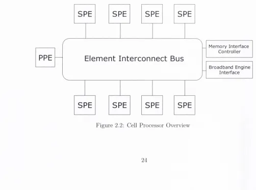
A single Cell chip consists of nine processors - one main processor called th e Pow
erP C Processor Element (P P E ) and eight co-]:>rocessors called Synergistic Processor
Elem ents (SPEs). All nine processors are connected via the Element Intercoim ect
Bus (EIB), a high-bandw idth memory-coherent bus which is used by th e processors
to com m unicate w ith each other, external memory and 1 /0 devices (see Figure 2.2).
It should be noted th a t a Cell does not necessarily have the complete set of eight
functioning SPUs - for m anufacturing the Playstation 3, two SPUs have actually
been disabled in order to increase th e yield.
PPE
SPE
SPE
SPE
SPE
SPE
SPE
SPE
SPE
M em ory In terfa ce C ontroller
B roadband E ngine In te rfa ce
E le m e n t I n t e r c o n n e c t Bus
[image:40.551.33.535.422.795.2]T h e P o w e r P C P r o c e sso r E le m en t
The P P E is the main processor th a t controls the CBE. It consists of a dual-threaded
SIMD 64-bit RISC PowerPC processor and a storage subsystem th a t governs mem
ory requests from the P P E and external requests to the P P E from other processors
(see Figure 2.3). The P P E is a general-purpose processor optimised for rmining
control-intensive software such as an operating system, coordinating all processes
running on Cell. The processor itself contains a 32KB level 1 instruction cache,
and a 32KB level 1 d ata cache. It also contains a VMX (Altivec) unit for SIMD
computations [28]. The storage subsystem includes a 512KB level 2 unified d ata
and instruction cache.
PowerPC P ro c esso r E lem en t (PPE)
32 KB
PowerPC
LI cachePrnrp«;<;nr
Unit (PPU) VMX ( A l t i v e c ) SIMD U n it
PowerPC Processor
Storage 512 KB
L2 cache Subsystem
(PPSS)
ik
To th e EIB ;
Figure 2.3: The PowerPC Processor Element (PPE)
T h e S y n e r g is tic P r o c e sso r E le m e n ts
The SPEs are where the bulk of Cell’s computational work is executed. Each SPE
consists of a specialised 128-bit SIMD RISC processor (the Synergistic Processor
[image:41.551.34.507.144.731.2]2 .4 T h e C ell B ro a d b a n d E n g in e
are optim ised to run com pute-intensive code a t th e expense of branch-prediction
and out-of-order-processing hardw are, allowing more of th e chip to be dedicated
to com putational work and reducing pipeline depth. Instead of dealing directly
w ith main memory, each SPU contains b o th a 128-entry register file and 256KB of
Local Store SRAM. The SPU uses this to store b o th d a ta and instructions. Like
th e PP U , each SPU also contains a VMX vector unit for SIMD operations. These
128-bit SIMD operations can work on a variety of d a ta sizes in parallel; one 128-bit
quadword, two 64-bit double words, four 32-bit words, eight 16-bit shorts or sixteen
8-bit chars. However, despite th e sim ilarities, th e S P U ’s instruction set is different
to th a t of the PP U , m eaning separate compilers must be used for th e different
processors.
The SPU contains two instruction pipes, and can dispatch two instructions si m ultaneously to th eir respective execution units. The first, nam ed th e ‘even’ pipe,
issues fixed/floating point and related bitwise operations. The ‘o d d ’ pipe covers
lo ad /sto re, branch, and word shuffle instructions. Therefore, m axim um SPE execu
tion speeds can be obtained by th e careful ordering of instructions to ensure th a t th e pipeline can operate a t full dual-issue rates.
Each MFC is responsil)le for transferring d a ta in and out of the Local Store of its
corresponding SPU. It does this through a local DMA controller allowing the SPU, P P U , or another SPLI to request a d a ta transfer to or from m ain memory. In this
way the S P E ’s DMA controller can autonom ously transfer d a ta to th e Local Store while th e SPU is processing other d ata, thus double buffering and hiding th e memory
latency behind com putation tim e. Each DMA transfer can be up to 16,384 bytes in size, and an SPU can have up to 16 outstan d in g DMA requests queued (or 2,048
if using a special DMA-list construct, ideally suited for s c a tte r/g a th e r operations).
Theoretical peak bandw idth between th e M FC and EIB is 25.6G B /s, w ith a to ta l
EIB peak bandw idth of 204.8G B /s. In practice, approxim ately 17-20GB/s SPU
th ro u g h p u t it typically achievable.
T h e E le m en t In te r c o n n e c t B u s
The EIB is a 4-ring stru ctu re used for passing d a ta between processors and I/O
S y n e r g is t ic P r o c e ss o r E lem en t (SPE)
Synergistic
R egister file128-entryProcessor
Unit (SPU)
256KBLocal Store
Memory
Flow
DMAController
Controller(MFC)
ik
To t h e EIB
Figure 2.4: The Synergistic Processor Element (SPE)
connected to th e M emory Interface Controller (MIC) and th e B roadband Engine
Interface (BEI).
The MIC su p p o rts connections to two R am bus Extrem e D a ta R ate (XDR) mem
ory channels. C om patible devices such as another Cell can be attach ed through the
BEI forming a cluster of Cells - indeed th e original patent filing for the Cell showed
four cores on a single die. This leads to scalability in two dimensions; the num ber of
processors enabled in any single Cell, and th e num ber of Cells networked together
by the BEI.
2 .4 .3
P r o g r a m m in g C ell
IBM released th e Cell SDK a t th e beginning of November 2005


![Table 3.1: Specifications of the Radeon 9200 (RV280 chipset) [4].](https://thumb-us.123doks.com/thumbv2/123dok_us/1037533.619251/58.551.28.536.51.394/table-specifications-radeon-rv-chipset.webp)
