Abstract— The flux and torque hysteresis bands are the only gains to be adjusted in Direct Torque Control (DTC) of induction motor. The torque ripple and harmonic loss of motor and switching loss of inverter greatly influence them. Hence, these variables must be observed in the control process to maximize performance of the system. In this paper, the effects of flux and torque hysteresis bands and the value of reference stator flux on inverter switching loss, harmonic loss, and torque ripple of induction motor are investigated. In order to find their optimum values, a cost function consisting motor harmonic losses, torque ripples, and inverter switching losses is defined. Minimizing this cost function leads to the optimum value of the hysteresis bands of torque and flux controllers. To validate the proposed work a simulation work is carried out and results are presented.
Index Terms-- Hysteresis bands, reference stator flux, torque ripple, DTC and Induction motor
I. INTRODUCTION
Ince the first developments of Direct Torque Control (DTC) concept [1],[2],it has been used in many ac drives applications because of its fast torque response and robustness against machine parameter variations. Its simple structure is due to using hysterisis comparators and switching vector table for both flux and torque control. Therefore, the only gains to be adjusted are the amplitudes of hysterisis bands [3,4]. The amplitude of hysterisis bands greatly influences the drive performance such as torque ripple, inverter switching frequency, and flux harmonics.
Manuscript received June 20, 2013; revised July 15, 2013
1
Y.P.Obulesu is with the Dept of Electrical Engineering, Lakireddy Balireddy College of Engg (Autonomous), Mylavaram, A.P, India (e-mail: [email protected]).
2
Y.Kusumaltha is with the Dept of Electrical Engineering, Lakireddy Balireddy College of Engg (Autonomous), Mylavaram, A.P, India (e-mail: [email protected]).
3
M.Vijaya Kumar is with the Dept of Electrical Engineering, Jawaharlal Nehru Technological University College of Engineering (Autonomous), Anantapur, A.P, India (e-mail: [email protected]).
4Ch.Saibabu is with the Dept of Electrical Engineering, University College
of Engineering (Autonomous), JNT University Kakinada, A.P,. India (e-mail: [email protected]).
Many papers have concerned the improvement of performance of DTC; but, in these papers [5, 6], there is not much analysis about the variation of flux harmonics and its effects on motor harmonic loss. In these papers, Total Harmonic Distortion (THD) of the input voltage is studied. However, iron loss is also affected by the order of harmonics, In addition, in these papers, there is not much simultaneous study about inverter switching loss, torque ripple, and harmonic loss of motor[7,8].
Direct Torque Controlled induction motor suffers from great torque ripple due to the fast response of the torque. Several improvements have been proposed to minimize the torque ripples [9, 10]. In earlier works the effects of sampling time and the hysteresis bands on the torque ripples are studied [11].
The value of the motor flux greatly influences the motor behavior. It is usually chosen as the nominal value in many applications. This is not an optimum operating point when the motor load is less than the nominal value. Therefore, reduction of the motor flux can help to increase the performance of the motor in these cases.
In this paper, the effect of flux and torque hysterisis bands on inverter switching loss, torque ripple, and harmonic loss of the motor is investigated and also a cost function is defined which leads to determination of optimum value of flux and torque hysterisis bands. Further, the effect of the reference value of the stator flux on the motor torque ripple is investigated. The effect of the flux reference variation on the motor power factor as well as torque dynamics is also presented.
II. DIRECT TORQUE CONTROL STRATEGY
The basic DTC block diagram is shown in Fig 1, is to choose the best vector of voltage which makes the flux rotate and produce the desired torque. During this rotation the amplitude of the flux rests in a pre-defined band. With a three phase voltage source inverter, there are six non-zero voltage vectors and two zero voltage vectors which can be applied to the machine stator terminals The stator flux vector can be estimated using measured current and voltage vectors:
(
)
s
V
sR I dt
s s
(1)Then, torque can be calculated using the components of the estimated flux and measured currents:
ep
(
d q
q d)
(2)Analysis of Effect of Hysteresis Bands and
Value of Reference Stator Flux on Torque
Ripple in Direct Torque Controlled Induction
Motor
1
Y.P.Obulesu,
Member, IAENG
,
2Y.Kusumalatha,
3M.Vijaya Kumar,
4Ch.Saibabu
Where p is the pole pair and d and q represent the Coordinate transformation components of the current and flux. This relation is another presentation of the original torque equation (3).
sin
,
m
e s r s r
s r
L
L L
(3)
and
2
1
Ms r
L
L L
Where LM is the magnetization inductance and LS and Lr
[image:2.595.66.543.80.269.2]are the stator and rotor inductance, respectively. Circular trajectory of stator flux is divided to six symmetrical sections referred to inverter voltage vectors. For each section, a proper vector set is proposed. The certain vectors are applied to motor so that amplitude of flux and torque remain constant. These vectors are selected from a lookup table in the control loop.
A. Iron loss
The hysterisis loss and the eddy current loss are lumped together as the core loss:
c h e (4)The power loss in the core due to the hysteresis effect is as:
h h nf
(5)Where B is the maximum of flux density, Kh is a constant and f is the frequency.
The eddy current loss in a magnetic core subjected to a time varying flux is [7]:
e e 2f
2 (6) Where Ke is a constant. It is obvious that iron loss isstrongly related to flux density and its frequency. Therefore, THD cannot be an accurate factor for studying the performance of the system [8].
In this study, harmonic core loss is normalized to the core loss of the fundamental component. Therefore, the i-th harmonic core loss versus core loss of the fundamental component is calculated by [8]
1
2
1
ei
V
iV
(7)
1
2
1
1
hi
V
iV
i
(8)Where Peiand Phiare the eddy current loss and hysteresis
core loss of the i-th harmonic, respectively, and Vi is the
amplitude of the i-th harmonic. The harmonic spectrum of motor flux is estimated and then motor harmonic losses are calculated based on (7) and (8).
B. Inverter switching Loss
Common inverter switch used in drive systems is IGBT. Switching loss of an IGBT is presented by (9).
Inverter loss on off
f
sw
( 9)Where Eon and Eoff are the switching energy loss at each
period and fswis the switching frequency. Although Eon and Eoff depend on the switched current and voltage; but, in this
study, they are considered as the fixed values found in the IGBT's datasheet. As it can be seen, switching frequency affects inverter switching loss and, hence, its useful life.
C. Motor torque ripple
The most important characteristic of DTC is its fast torque response. When a proper vector is applied to motor, the stator flux vector rotates very fast and the angle between stator flux and rotor flux is increased. Therefore, the amplitude of motor torque is increased according to (3). If
[image:2.595.307.547.359.464.2]sampling period Ts is not low enough, then torque waveform usually jumps to the out of torque hysteresis band. Therefore, motor which is derived with DTC usually suffers from large torque ripple. This large torque ripple has undesired effect on motor useful life and its load. The torque ripple, Te, is divided to two parts as shown in the following
e 1 2 (10)Where
1
1
1
ss r
(11)2 m
.
s m s r s
s r
L
V
j
j
L L
(12)In these relations, ωm is the motor speed and
s and
r arestator and rotor time constants, respectively. The first contribution is due to the stator and rotor resistances and acts in order to reduce the absolute value of the torque. This contribution is proportional to the torque value and is independent of voltage vector and motor speed. The second contribution represents the effect of me applied voltage vector on the torque variation and is dependent on motor speed.
D. Construction of Cost function
The torque ripple, motor harmonic loss, and inverter switching loss are the components which are observed in optimization of DTC. The relation (13) shows a general
form of a cost function which includes these components.
,
1 Inverter loss 2 Motor Harmonic Loss 3 actC f W W W (13)
Where W1, W2 and W3 are weighting functions of inverter
switching loss, motor harmonic loss, and actual torque ripple respectively. These weighting functions vary in different cases according to the importance of the cost function components. For example, if reduction of torque ripple is
Fig. 2. Flow chart of optimization process
desired, then the weighting function of torque ripple, W3, is
increased. Fig 2 shows the flowchart of optimization process.
III. ANALYSIS OF EFFECT OF REFERENCE STATOR FLUX Torque ripple minimization is a major difficulty in Direct Torque Control of induction motors. The reference value of the motor flux greatly influences the torque ripple. On the other hand, many motors work in an operating cycle, which includes load intervals of less than their nominal power. In these situations, it is not necessary to set their flux value as the nominal value. In this section, the effect of the reference value of the motor flux on the motor torque ripple is investigated. The effect of the flux reference variation on the motor power factor as well as torque dynamics is also presented. Simulation results of the proposed method on the performance of Induction motor are also discussed.
Reduction of torque ripple is the desired effect of flux value, but other parameters of motor are also affected with the value of motor flux. The parameters, which are affected, are described below.
A. Torque ripple
When a proper vector is applied to motor, the stator flux vector rotates very fast and the angle between the stator flux and rotor flux is increased. Therefore, the amplitude of the motor torque is increased according to (3). If sampling period of 75% is not low enough, then torque waveform usually jumps to the out of torque hysteresis band. Therefore, motor that is derived with DTC usually suffers from large torque ripple. This large torque ripple has undesired effect on motor useful life and its load. The torque ripple T is divided into two parts as represented in (10), (11) & (12). It is clear from (11) and (12) the value of motor flux has no effect on the first component of torque ripple; while it influences mainly the second part. From the dynamic equations of the induction machine, after simplifications, the rotor flux can be expressed in terms of stator flux as follows:
2
M r
r r
s r M s r s
L R
L R
j L
L L
(14)Therefore, reduce the stator flux bands to reduce the rotor flux according to (14) and it leads to reduction of the torque ripple (11). Especially for low speed, the torque ripple component (12) can be approximated as:
2 .
M
s r s
s r
L
V j L L
(15)
The maximum value of this component of torque ripple is as follows
2 max
M
s r s
s r
L
V
L L
M r s s r L L L
(16)
reference value in low speed range because the rising slope of torque is very sharp. Thus, decreasing the second component of torque ripple helps to decrease the torque ripple especially in low speed.
B. Motor input current and power factor
Reduction of motor flux leads to the reduction of magnetizing current. Therefore, the value of motor input current is decreased decreasing the magnetizing current leads to the reduction of the reactive component of motor current. Thus, the motor power factor is improved.
C. Torque dynamics
The value of motor flux determines the torque time constant. The greater motor flux leads to the smaller torque time constant and vice versa.
D. Motor core loss
The hysteresis loss and the eddy current loss are lumped together as the core loss as given in (4). The power loss in the core due to the hysteresis effect is given in (5). The eddy current loss in a magnetic core subjected to a time varying flux is given in (6). It is obvious that iron loss is strongly related to flux density. Therefore, the motor core loss is reduced in the proposed method.
IV. SIMULATION RESULTS
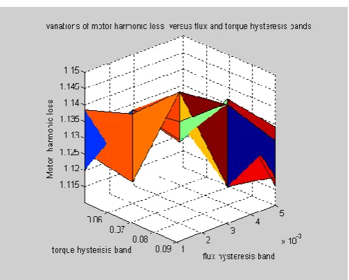
The parameters of the induction motor used in this simulation are given in Appendix. The value of the sampling interval adopted in the simulations is 25 microseconds. Fig 3 shows the variations of torque ripple versus torque and flux hysteresis bands. From which, it can be noted that the minimum total motor torque ripple=0.4180Nm at flux hysteresis band=0.005 and torque hysteresis band=0.05. Fig 3 shows the variations of motor harmonic loss. The iron loss is calculated according to the (4) and (5). The calculation of motor harmonic loss is based on the relation between flux harmonics and iron loss. Therefore, at the first step of optimization loop the flux harmonics for given operating point are estimated. The base of these variations is the loss of fundamental component of flux. From Fig 4, it can be noted that the Minimum motor harmonic loss=1.1157 at flux hysteresis band=0.004, torque hysteresis band=0.08. Fig 5(a), (b), & (c) shows the variations of cost function versus flux and torque hysteresis bands amplitudes for different weighting functions. From Fig 5(a), it is observed that the minimum cost function is 3.5721 at the weighting functions, W1=0.3,W2=0.4,W3=0.3. From Fig 5(b), it is noted that the
minimum cost function is 2.5443 at weighting functions, W1=0.2, W2=0.3, W3=0.5. Further, from Fig 5(c), it can be
observed that the minimum cost function is 1.5165 at the weighting functions, W1=0.1, W2=0.2, W3=0.7. From the Fig
5(a), (b), & (c), it can be observed that Fig 5(c) shows the variations of cost function versus flux and torque hysteresis bands amplitudes for W1=0.1, W2=0.2 and W3=0.7 gives a
smaller value. In this case the importance of torque ripple has been increased via increasing its weighting function. Respective hysteresis band values for this minimum are
equal to
=0.005 and
e =0.06 and the values of costfunction and its components in this minimum are summarized as follows:
Minimum inverter switching loss = 10 Minimum motor harmonic loss = 1.1157 Minimum torque ripple =0.4180
[image:4.595.305.554.341.534.2]Minimum value of cost function =1.5165
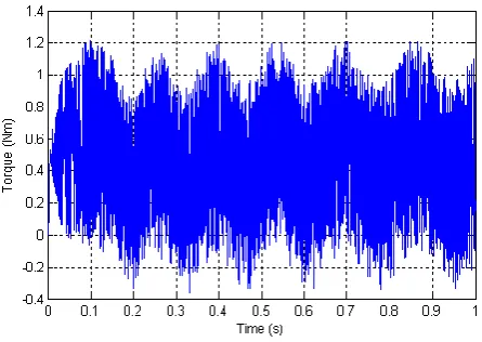
Fig 6 shows flux spectrum of the induction motor. Fig 7(a) and 7(b) shows the stator flux waveform at its nominal value and reduced level respectively. Fig 7(c) shows the variations of the motor torque when the reference values of the torque and flux are 0.5 Nm (25% of the nominal torque) and 1Wb, respectively. Fig 7(d) shows the variations of the motor torque when the reference values of torque and flux are 0.5 Nm and 0.6 Wb. From which, It can be observed that the torque ripple has been reduced for reduced stator flux value. Figs 7(e) and 7(f) showed the stator current waveforms for the flux values of 1.0Wb and 0.6Wb, respectively. It can be seen that the stator current amplitude is reduced for the reduced flux value. Therefore, motor power factor is improved for the operating power, which is less than the nominal power.
[image:4.595.300.556.344.765.2]Fig. 3. Variations of torque ripple versus torque and flux hysteresis bands.
[image:4.595.305.557.567.769.2]Fig. 5(a). Variations of cost function versus flux and torque hysteresis bands, (for W1=0.3,W2=0.4,W3=0.3)
Fig. 5(b). Variations of cost function versus flux and hysteresis bands, (for w1=0.2,w2=0.3,w3=0.5)
[image:5.595.48.291.51.244.2]Fig. 5(c). Variations of cost function versus flux and torque hysteresis bands (for w1=0.1,w2=0.2,w3=0.7)
Fig. 6. Flux spectrum of induction motor
[image:5.595.305.567.51.249.2] [image:5.595.47.577.73.728.2] [image:5.595.56.349.250.738.2] [image:5.595.325.565.290.494.2]Fig. 7(c). Motor torque waveform in nominal flux
Fig. 7(d). Motor torque waveform in reduced flux
Fig. 7(e). Stator current waveform in nominal flux
Fig. 7(f). Stator current waveform in reduced flux
V. CONCLUSION
In this paper, the influence of the hysteresis bands on the performance of DTC of an induction motor has been investigated. Results showed that inverter switching loss, motor harmonic loss, and motor torque ripple are influenced by the hysteresis bands. Motor drive has been tested for different hysteresis band values and it has been found that the drive performance is good for specific values of the hysteresis bands i.e torque hysteresis band = 0.06, flux hysteresis band = 0.005. The influence of the reference value of the stator flux on the DTC of an induction motor was also investigated. From the results, it is noticed that the value of the stator flux influences the torque ripple of the motor. Therefore, the optimum value of flux is not equal to the nominal value when motor power is less than the nominal value. The motor power factor is also improved with reduced flux value, but the torque dynamics have slower
response because of the reduction in flux value.
APPENDIX Motor details:
1HP, 0.75KW, 220 V, 4-pole, 1680rpm. Stator circuit resistance = 9.6 Ohm, Rotor circuit resistance = 7.008 Ohms, Self inductance of stator circuit = 0.8896 H, Self inductance of rotor circuit = 0.8896 H, Mutual Inductance = 0.8794 H,
Moment of inertia = 0.009 Kg-m2.
REFERENCES
[1] M.Depenbrock, “Direct Self-Control(DSC) of inverter fed induction machine”, IEEE Trans. power electronics ,vol.3,no.4,pp.420-429,1988.
[2] P.C.costa, A.S.Carvalho, M.F.Chousal, and C.A.Martins, “Direct Torque Control Frequency Analysis,” in Proc. IEEE AMC Conference, pp.21-24, 1998.
[3] Yongdong, L., Jianwen, S., Baojun, S, "Direct torque control of induction motor for low speed drives considering discrete effects of control and dead time of inverters", Proceedings of the 1997 IEEE IAS Annual Meeting, pp. 781-788, 1997.
[4] J.K.Kang et al, “Direct torque control of induction machine with variable amplitude control of flux and torque hysteresis bands”, in
Proc. of Int.Conf of Elect. Mach. and Drives, pp. 640-642., 1999. [5] D.Casadei, G.Grandi, G.Sena ,and A.Tani , “Effects of flux and
Torque hysteresis band amplitude in direct torque control of induction machines,” in proc. IEEE 1994 Power Electronics Specialist Conference,1994,pp.299-305.
[6] I. El Hassan, X. Roboam, B. de Fornel, and E. V. Westerholt, “Torque dynamic behavior of induction machine DTC in 4-quadrant operation”, in Proc. ISIE ’97, Guimaraes, Portugal, July 7–11, 1997, pp. 1034–1038
[7] D. Casadei, G. Serra, and A. Tani, “Analytical investigation of torque and flux ripple in DTC schemes for induction motors”, in
Proc. IECON’ 97, New Orleans, LA, pp. 552–556.
[8] J. Faiz, M. B. B. Sharifian, and V. Fedak, “Minimization of current harmonics of DTC controller using a suitable switching pattern”, in
Proc. Ninth Int. Conf. Power Electron. Motion Cont., Vol. 3, Kosice, Slovak Republic, 2000, EPE-PEMC 2000, pp. 161–166. [9] D. Casadi, G. Serra, and A. Tani, "Implementation of a direct
torque control algorithm for induction motors based on discrete space vector modulation", IEEE Trans, on Power Electronics, Vol. 15, No. 4, pp. 769-777, 2000
[10] J.K.Kang and S.k.Sul, “Torque ripple minimization strategy for direct torque control of induction motor,” in Proc.IEEE 1998 Industrial Electronics Society Annual Meeting ,pp.438-442,1998. [11] S.Kaboli, M.R. Zolghadri, H. Homaifar, “Effects of sampling time
on direct torque controlled induction motor”, in Proc. of the IEEE International Symposium on Industrial Electronics, (ISIE03),
[image:6.595.58.281.58.216.2]