Dinesh et al. World Journal of Engineering Research and Technology Nagarajan et al. World Journal of Engineering Research and Technology
DIRECT TORQUE CONTROL OF INDUCTION MOTOR USING FUZZY LOGIC
D. Vinoth1, D. Dinesh Kumar*2,R. Aadhith Krishna3 and M. Palanisamy4
1
Assistant Professor, EEE Department, Muthayammal College of Engineering, Rasipuram.
2,3,4
UG Students, EEE Department, Muthayammal College of Engineering, Rasipuram.
Article Received on 06/02/2019 Article Revised on 25/02/2019 Article Accepted on 17/03/2019
ABSTRACT
This paper presents of induction motors has increased tremendously
since the day of its invention. They are being used as actuators in
various industrial processes, robotics, house appliances (generally
single phase) and other similar applications. The reason for its day by
day increasing popularity can be primarily attributed to its robust
construction, simplicity in design and cost effectiveness. These have also proved to be more
reliable than DC motors. Apart from these advantages, they have some unfavorable features
like their time varying and non-linear dynamics. Speed control is one of the various
application imposed constraints for the choice of a motor. Hence, in the last few years various
methods for the speed control have been developed
KEYWORDS: Micro Grid Protection, Earthling Systems, Fault Current, Touch Voltage, Micro Sources and Inverters.
INTRODUCTION
The induction motor finds its place amongst more than 85% of industrial motors as well as in
its single-phase form in various domestic usages. Markedly a constant-speed motor with
shunt characteristic, speed drops only by a few percent from no-load to full load. Hence in the
past, induction motors have been used primarily in constant speed applications. Traditional
methodologies employing speed control have either been high-priced or very inefficient,
unlike the dc motor in which the presence of commutator and brushes require recurrent
maintenance make dc motor drives improper for use in hazardous and polluted environments.
World Journal of Engineering Research and Technology
WJERT
www.wjert.org
SJIF Impact Factor: 5.218*Corresponding Author
D. Dinesh Kumar
UG Students, EEE
Department, Muthayammal
College of Engineering,
produced. It is called a rotating field since its poles do not remain in a fixed position on the
stator but go on shifting their positions surrounding the stator. The magnitude of this field is
constant and equal to 1.5ɸm, where ɸm is the maximum flux due to any phase. On energizing
the three phase stator from a three phase supply, a rotating magnetic field sets up round the
stator which rotates at synchronous speed ns. This field passes through the air-gap and cuts
the stationary rotor conductors. Owing to the relative speed between the rotating flux and the
static rotor, electromotive forces are induced in the rotor conductors. For the reason that the
rotor circuit is short-circuited, currents start flowing in the rotor conductors. Again, these
conductors are placed in the magnetic field produced by the stator. As a result, mechanical
force acts on the rotor conductors. A torque, produced as a result of this force, tends to move
the rotor in the same direction as the rotating field. This is justified by Lenz law, according to
which the direction of rotor currents will be such that they have a tendency to oppose the
cause producing them. Now, the relative speed between the rotating field and the standstill
rotor conductors is the cause generating the rotor currents. Thus to reduce this speed, the
rotor starts running in the same direction as that of stator field and tries to catch it. Clearly,
the rotor speed N is always less than the stator field speed‟s‟.
2. Speed Control of Induction Motors
The speed control of induction motors involves more complexity than the control of dc
motor, especially if comparable accuracy is desired. The main reason for the same can be
attributed tot he complexity of the mathematical model of the induction machine, as well as
the complicated power converters supplying this motor. Variable speed induction motor
drives employ various control algorithms.
2.1 Speed Regulation as a Means of Controlling a Process
Let us consider the process of driving to work. Driving at the highest possible speed would
probably cause an accident. And driving at a single speed that will be safe for every portion
well with the route minimizes the time to accomplish the objective of the process within
limits of reliable operation. The process control benefits that may be provided by an
adjustable speed drive are as follows
1. Smoother operation.
2. Acceleration control as an added incentive.
3. Varying operating speed for each process.
4. Compensates for fluctuating process parameters.
5. Permits slow operation for setup purpose.
6. Allows accurate positioning.
7. Provides torque control.
2.2 Types of Speed Control 2.2.1 Scalar Control
The induction motor draws the rated current and delivers the rated torque at the base speed.
When the load is increased (over-rated load), while running at base speed, the speed drops
and the slip increases. The motor can take up to 2.5 times the rated torque with around 20%
drop in the speed. Any further increase of load on the shaft can stall the motor. The torque
developed by the motor is directly proportional to the magnetic field produced by the stator.
So, the voltage applied to the stator is directly proportional to the product of stator flux and
angular velocity. This makes the flux produced by the stator proportional to the ratio of
applied voltage and frequency of supply. By varying the frequency, the speed of the motor
can be varied. Therefore, by varying the voltage and frequency by the same ratio, flux and
hence, the torque can be kept constant throughout the speed range. Stator Voltage (V) ∝
[Stator Flux (Φ)] x [Angular Velocity (ω)] V ∝ Φ * 2 Π F Φ ∝ V/F
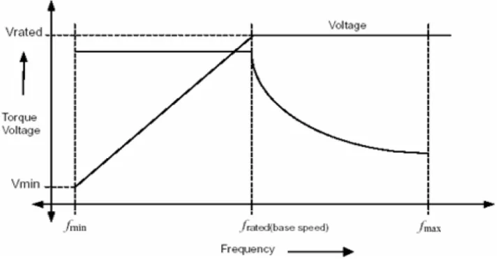
This makes constant Volts/hertz the most common speed control of an induction motor. Fig 1
shows the relation between the voltage and torque versus frequency. It demonstrates torque
voltage and frequency being increased up to the base speed. At base speed, the voltage and
frequency reach the rated values as listed in the nameplate. The motor can be driven beyond
base speed by increasing the frequency further. However, the voltage applied cannot be
Fig 1: Speed Torque Characteristics with V/f Control.
Therefore, only the frequency can be increased, which results in the field weakening and the
torque available being reduced. Above base speed, the factors governing torque become
complex, since friction and windage losses increase significantly at higher speeds. Hence, the
torque curve becomes nonlinear with respect to speed or frequency.
2.2.2 Vector Control
AC motors, particularly the squirrel-cage induction motor (SCIM), enjoy several inherent
advantages like simplicity, reliability, low cost and virtually maintenance-free electrical
drives. However, for high dynamic performance, their control remains a challenging problem
because they exhibit significant non-linearity and many of the parameters vary with the
operating conditions. Field orientation control or IVC of an induction machine achieves
decoupled torque and flux dynamics leading to independent control of the torque and flux.
Fig.2. shows block diagram of speed control system using vector control.
Vector control is a technique which allows the induction motor to act like a Separately
excited DC machine with decoupled control of torque and flux, making it possible to operate
the induction motor as a high-performance four-quadrant servo drive. The principle of vector
control was devised by Hassel and Blacked and was developed by Leonard. In separately
excited DC machine with a constant field excitation, torque is directly proportional to
armature current. The orthogonal relationship between air gap flux and torque is independent
of the speed of rotation so that the torque of the DC machine is proportional to the product of
the flux and armature current. If the magnetic saturation is ignored, field flux is proportional
to field current and is unaffected by armature current because of the orthogonal orientation of
the stator and rotor fields.
Therefore, direct control of armature current gives direct control of motor torque and fast
response, because motor torque can be altered as rapidly as armature current can be altered.
The vector control technique provides a similar control strategy for the induction motor. The
idea behind vector control is that the stator current of the induction motor is decomposed into
orthogonal components as a magnetization component (flux producing) and a torque
component. These components are controlled individually. In order to obtain high dynamic
performance of the induction motor, the magnetizing current component is maintained at its
rated level while the torque should be controlled through the torque component for the stator
current.
3. Direct Torque Control
Direct torque control (DTC) is one method used in variable frequency drives to control the
torque (and thus finally the speed) of three-phase AC electric motors. This involves
calculating an estimate of the motor's magnetic flux and torque based on the measured
voltage and current of the motor. Stator flux linkage is estimated by integrating the stator
voltages. Torque is estimated as a cross product of estimated stator flux linkage vector and
measured motor current vector. The estimated flux magnitude and torque are then compared
with their reference values. If either the estimated flux or torque deviates from the reference
more than allowed tolerance, the transistors of the variable frequency drive are turned off and
on in such a way that the flux and torque errors will return in their tolerant bands as fast as
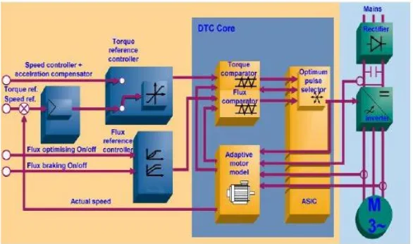
Fig. 3: Block diagramof DTC.
3.1 Direct Torque Control Principle
Direct Torque Control (DTC) is an optimized AC drives control principle where inverter
switching directly controls the motor variables: flux and torque. The measured input values to
the DTC control are motor current and voltage. The voltage is defined from the DC-bus
voltage and inverter switch positions. The voltage and current signals are inputs to an
accurate motor model which produces an exact actual value of stator flux and torque every 25
microseconds. Motor torque and flux two-level comparators compare the actual values to the
reference values produced by torque and flux reference controllers. The outputs from these
two-level controllers are updated every 25 microseconds and they indicate whether the torque
or flux has to be varied. Depending on the outputs from the two-level controllers, the
switching logic directly determines the optimum inverter switch positions. Therefore every
single voltage pulse is determined separately at "atomic level". The inverter switch positions
again determine the motor voltage and current, which in turn influence the motor torque and
flux and the control loop is closed.
3.2 Stator Flux Control
The IM equations, in a stator reference frame, are defined by: where Rs and Rr are the stator
and rotor resistances. Ls and Lr are the mutual stator and rotor inductances. The stator flux is
estimated from the measure of stator current and voltage and their transformation in the
subspace. So The stator flux module and the linkage phase are given by So, the variation of
the stator flux is directly proportional to the stator voltage, thus the control is carried out by
varying the stator flux vector by selecting a suitable voltage vector with the inverter. A two
level hysteresis comparator could be used for the control of the stator flux.
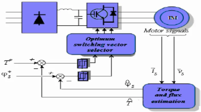
3.4 Direct Torque Control with Three-Level Inverter
The basic functional blocks used to implement the DTC scheme are represented in Figure.
The instantaneous values of the stator flux and torque are calculated from stator variable by
using a closed loop estimator. Stator flux and torque can be controlled directly and
independently by properly selecting the inverter switching configuration.
Fig. 5: DTC scheme for AC motor with three level inverter.
3.5 Stator Flux and Electromagnetic Torque
The calculated magnitude of stator flux and electric torque are compared with their reference
values in their corresponding hysteresis comparators as are shown in Fig 3.4. Finally, the
outputs of the comparators with the number of sector at which the stator flux space vector is
Fig. 6: Stator flux and torque hysteresis comparator.
The selected voltage vector will be applied to the induction motor at the end of the sample
time.
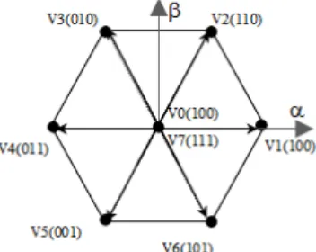
Fig. 7: Partition of d-q plane into six angular vectors.
Neglecting the stator resistance, implies that the end of the stator flux vector will move in the
direction of the applied voltage vector, as shown in Fig 5. Is the initial stator flux linkage at
the instant of switching. To select the voltage vectors for controlling the amplitude of the
stator flux linkage, the voltage vector plane is divided into six regions, as shown in Fig 6. In
each region, two adjacent voltage vectors, which give the minimum switching frequency, are
selected to increase or decrease the amplitude of, respectively. For instance, vectors and are
selected to increase and decrease the amplitude of when is in region one and is rotating in a
counter-clockwise direction. In this way, can be controlled at the required value by selecting
the proper voltage vectors. Fig 7 shows how the voltage vectors are selected for keeping
within a hysteresis band when is rotating in the counter clockwise direction.
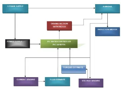
4. Hardware Implementation
Fig. 8: Functional block diagram.
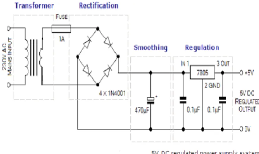
4.1 Power Supply System
A power supply is a device that supplies electrical energy to one or more electric loads. The
term is most commonly applied to devices that convert one form of electrical energy to
another, though it may also refer to devices that convert another form of energy (e.g.,
mechanical, chemical, solar) to electrical energy. A regulated power supply is one that
controls the output voltage or current to a specific value; the controlled value is held nearly
constant despite variations in either load current or the voltage supplied by the power supply's
energy source. Every power supply must obtain the energy it supplies to its load, as well as
any energy it consumes while performing that task, from an energy source. A power supply
may be implemented as a discrete, stand-alone device or as an integral device that is
hardwired to its load. In the latter case, for example, low voltage DC power supplies are
commonly integrated with their loads in devices such as computers and household
Fig. 9: Power supply circuit for PIC 16F877.
The PIC16F887 having 40pins and 5 ports. In this PIC microcontroller the first pin is
connected with the master clear circuit, it is used for the clear purpose. For this circuit we
will provide +5v supply. For this project we won‟t use port A and port E. 11th and 12th pin
for the purpose of VSS and VDD. For RF we will provide +5v supply. In power supply
circuit first the step down transformer will provide 12v AC supply. Then this alternating
current converted into direct current with the help of bridge rectifier. At last with the help of
particular rectified IC we can get particular voltage level.
4.3 Working
The torque and stator flux of the induction motor is estimated and compared with the
reference values independently. The torque and flux errors produced are given as input to the
fuzzy logic controller where the linguistic inputs are processed as per the fuzzy rules table
and crisp output is produced. The controlled output can be applied as a firing signals to the
inverter through IR2110 (Driver IC) and Optocoupler.TheOpto isolation of signals is
necessary as the control signals from the controller is digital one where as the firing signals to
be applied to inverter should be analog one. Thus torque and flux of the induction motor is
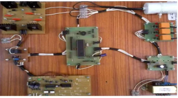
Fig. 10: Hardware setup.
5. CONCLUSION
In this paper, we present a kind of fuzzy torque control system for induction motor based on
fuzzy control technique. The simulation results suggest that FLDTC of induction machine
can achieve precise control of the stator flux and torque. Compared to conventional DTC,
presented method is easily implemented, and the steady performances of ripples of both
torque and flux are considerably improved. The main improvements shown are: • Reduction
of torque and current ripples.• No flux droppings caused by sector changes circular trajectory.• Fast torque response. • Zero-steady-state torque and flux.
REFERENCES
1. Takahashi and T. Noguchi, ″A New Quick-Response and High- Efficiency Control
Strategy of Induction Motor, ″IEEE Trans. On IA, Sept/Oct 1986; 22(5): 820-827.
2. M. Depenbrock, ″Direct self – Control (DSC) of Inverter– Fed Induction Machine,″ IEEE
Trans. Power Electronics, Oct 1988; 3(4): 420-829.
3. D.Casadei, F.Profumo, G.Serra and A.Tani, ″FOC and DTC:Tox Viable Schemes for
Induction Motors Torque Control,″ IEEE Trans. Power Electronics. On PE, Sept2002;
17(5).
4. C.Nagarajan and M.Madheswaran, „Experimental verification and stability state space
analysis of CLL-T Series Parallel Resonant Converter with fuzzy controller‟ - Journal of
Electrical Engineering, 2012; 63(6): 365-372.
5. R.Raja and C.Nagarajan, “Performance Analysis of LCL-T Filter Based 2 Stage Single
Phase Gird Connected Module with ANN Controller using PV Panel," Current Signal
8. M.Madheswaran, C.Nagarajan, “DSP Based Fuzzy Controller for Series Parallel
Resonant converter”, Frontiers of Electrical and Electronic Engineering, 2012; 7(4):
438-446.
9. C.Nagarajan, “Single-Stage High-Frequency Resonantac/AC Converter Using Fuzzy
Logic and Artificial Neural networks‟, Conference on Emerging Devices and Smart
Systems (ICEDSS), 2nd and 3rd March, organized by mahendra Engineering College,
Mallasamudram, 2018; 30-37.
10.E Geetha, C Nagarajan, “Induction Motor Fault Detection and Classification Using
Current Signature Analysis Technique”, Conference on Emerging Devices and Smart
Systems (ICEDSS), 2nd and 3rd March, organized by mahendra Engineering College,
Mallasamudram, 2018; 48-52.
11.GS SatheeshKumar, C Nagarajan, ST Selvi, “A Virtual Impedance Based Analysis of
Dynamic Stability in a Micro-Grid System”, Conference on Emerging Devices and Smart
Systems (ICEDSS), 2nd and 3rd March, organized by mahendra Engineering College,
Mallasamudram, 2018; 38-41.
12.CS Lakshmi, C Nagarajan, “Neural Controlled Multi-Level Inverter Based DVR for
Power Quality Improvement”, Conference on Emerging Devices and Smart Systems
(ICEDSS), 2nd and 3rd March, organized by mahendra Engineering College,
Mallasamudram, 2018; 42-47.
13.S Thirunavukkarasu, C Nagarajan, “Performance Analysis of BLDC Motor Drive for
Feed Drives”, Conference on Emerging Devices and Smart Systems (ICEDSS), 2nd and 3rd
March, organized by mahendra Engineering College, Mallasamudram, 2018; 67-70.
14.JP Daniel, C Nagarajan, “Hybrid Filter for Distorted Voltage Source in Microgrids”,
Conference on Emerging Devices and Smart Systems (ICEDSS), 2nd and 3rd March,
organized by mahendra Engineering College, Mallasamudram, 2018; 11-15.
15.K Umadevi, C Nagarajan, “High Gain Ratio Boost-Fly Back DC-DC Converter using
and 3rd March, organized by mahendra Engineering College, Mallasamudram, 2018; 64-66.
16.C.Nagarajan and M.Madheswaran, “Experimental Study and steady state stability
analysis of CLL-T Series Parallel Resonant Converter with Fuzzy controller using State
Space Analysis”, Iranian Journal of Electrical and Electronic Engineering, 2012; 8(3):
259-267.
17.C. Santhana Lakshmi and C. Nagarajan, “Multiconverter Technology Based Voltage
Compensation for Photovoltaic System” Ecology, Environment and Conservation, 2017;
23: 226-229.
18.C.Nagarajan and M.Madheswaran, “Stability Analysis of Series Parallel Resonant
Converter with Fuzzy Logic Controller Using State Space Techniques”, Electric Power
Components and Systems, 2011; 39(8): 780-793.
19.C.Nagarajan, M.Muruganandam and D.Ramasubramanian – „Analysis and Design of
CLL Resonant Converter for Solar Panel - Battery systems- International Journal of
Intelligent systems and Applications, 2013; 5(1): 52-58.
20.C.Nagarajan and M.Madheswaran, “Experimental Study and Comparative Analysis of
CLL-T and LCL-T Series Parallel Resonant Converter with Fuzzy/ PID Controller”,
Journal of Electrical Engineering, 2011; 11(3): 122-129.
21.C.Nagarajan and M.Madheswaran, “Analysis and Simulation of LCL Series Resonant
Full Bridge Converter Using PWM Technique with Load Independent Operation” has been presented in ICTES‟08, a IEEE / IET International Conference organized by
M.G.R.University, Chennai, 2007; 1: 190-195.
22.C. Nagarajan, M.Madheswaran and D.Ramasubramanian, “Development of DSP based
Robust Control Method for General Resonant Converter Topologies using Transfer
Function Model,” Acta Electrotechnica et Informatica Journal, 2013; 13(2): 18-31.
23.S.Sathish Kumar and C.Nagarajan, “Performance - Economic and Energy Loss analysis
of 80 KWp Grid Connected Roof Top Transformer less Photovoltaic power Plant,”
Circuits and Systems, 2016; 7(6): 662-679.
24.D.Casadei and G.Serra, ″Implementation of Direct Torque Control Algorithme for
Induction Motors Based on Discrete Space Vector Modulation,″ IEEE Trans. Power
Electronics, July 2002; 15(4).
25.Y.Xia W.Oghanna "Study on Fuzzy Control of Induction Machine With Direct Torque