Preparation of Nano-Structured La
0.6Sr
0.4Co
0.2Fe
0.8O
3¹¤Cathode
for Protonic Ceramic Fuel Cell by Bead-Milling Method
Hiroyuki Oda
1,+, Yuji Okuyama
2, Takaaki Sakai
3and Hiroshige Matsumoto
1,4,51Department of Molecular and Material Sciences, Interdisciplinary Graduate School of Engineering Sciences, Kyushu University, Kasuga 816-8580, Japan
2INAMORI Frontier Research Center (IFRC), Kyushu University, Fukuoka 819-0395, Japan 3Center for Molecular Systems (CMS), Kyushu University, Fukuoka 819-0395, Japan
4International Institute for Carbon-Neutral Energy Research (I2CNER-WPI), Kyushu University, Fukuoka 819-0395, Japan 5Next-Generation Fuel Cell Research Center (NEXT-FC), Kyushu University, Fukuoka 819-0395, Japan
Nano-structured La0.6Sr0.4Co0.2Fe0.8O3¹¤(LSCF6428) cathode for protonic ceramic fuel cell (PCFC) prepared from planetary bead-milled
nanoparticles was investigated. The cathode made by the bead-milled particles showed a porous structure consisting of homogeneous size particles and pores in the range 100 nm. The PCFC comprised of this cathode, Ni anode and BaCe0.6Zr0.2Y0.2O3¹¤(BCZY622) electrolyte increased the cell performances about 6 times that of the cell using the cathode without milling. The cathode preparation using bead-milling is effective in improving the cell performance with an expanded contact area of the cathode/electrolyte interface due to decreasing particle size and good adhesion of the particles to the electrolyte. [doi:10.2320/matertrans.M2013426]
(Received November 26, 2013; Accepted January 20, 2014; Published March 25, 2014)
Keywords: protonic ceramic fuel cell (PCFC), cathode, La0.6Sr0.4Co0.2Fe0.8O3¹¤, bead-milling
1. Introduction
Protonic ceramic fuel cells (PCFCs) are solid oxide fuel cells (SOFCs) that use proton-conducting oxides as the electrolyte.14) The activation energy of the proton conduc-tion is typically in the range of 0.30.65 eV58)and is lower than that of oxide ion conduction in solid oxides used for conventional SOFCs. Thus PCFC can work within inter-mediate temperature region (400600°C) which is lower than those of the conventional SOFCs based on a doped zirconia oxideion-conducting electrolyte. PCFC consists of a proton conducting oxide as the electrolyte, a metallic catalyst, most typically combined with the electrolyte material as the anode and a mixed ionelectron conductor (MIEC) as the cathode.912) The electrolyte and electrode resistance increases as the operation temperature decreases and therefore the electrode activity should be improved to operate PCFC at such intermediate temperatures.
Extensive research has been conducted on PCFC cathodes with the major aim of reducing the operation temperature and improving cell performance. Some reported studies have considered the modification of the cathode structure, such as the preparation of MIEC combined with the electrolyte. For example, Ricoteet al.reported the evaluation of the cathode performance consisting of BaCe0.2Zr0.7Y0.1O3¹¤as backbone structure with infiltrated La0.58Sr0.4Co0.2Fe0.8O3¹¤particles.12) This study succeeded in increasing the contact area of the electrolyte/cathode interface and reducing the area specific resistance of the cathode compared to the La0.58Sr0.4Co0.2 -Fe0.8O3¹¤cathode only. To obtainfine structure cathode was made by spray coating or spray pyrolysis of their metal nitrate solution.1315)The thin film cathode was prepared by deposition technique under high vacuum such as pulse laser deposition and chemical vapor deposition.16,17)
The authors found that planetary bead-milling was important in grinding the solid oxides into nanoparticles sizes.18,19)In contrast to bottom-up methods, such as the sol gel methods, hydrothermal synthesis and so forth, planetary bead-milling is categorized as a top-down approach that prepares nanoparticles by crashing the starting coarse particles and thus can be used for various solid materials. This important aspect of planetary bead-milling is advanta-geous to a wide range of solid oxide and is particularly useful to prepare nanoparticles for electrode materials, which usually have complicated chemical compositions and thus difficult to be prepared by bottom-up methods. In addition, the grinding is a simple process giving the planetary bead-milling an advantage of easiness to manage the bead-milling procedure and the ability for large scale production. No extensive study on the use of bead-milling of electrode material particularly by use offine beads with a size less than 100 µm for solid oxide fuel cells have been reported so far. We have reported the use of bead-milling to pulverize Sm0.5Sr0.5CoO3 (SSC55) for the preparation of PCFC cathodes in combination with proton-conducting oxide electrolyte BaCe0.6Zr0.2Y0.2O3¹¤ (BCZY622).20) The SSC55 powder was successfully milled to obtain homogeneously dispersed slurry in ethanol. One problem of the slurry was the shrinkage during drying and baking, resulting is the formation of cracks. We found that using the slurry prepared by bead-milling with the addition of polyvinylpyrrolidone (PVP) effectively avoided the shrinkage in the cathode. PVP covered SSC55 nanoparticles showed a good adhesive behavior for the electrolyte disk even after drying and baking. The cathode made of the milled slurry showed lower overpotential than that without milling at intermediate temperature, resulting in better performance when used for PCFC. The use of planetary bead-milled slurry was effective in avoiding the peeling of the electrode in comparison with the cathode prepared without milling SSC55. However, due to a large discrepancy in the thermal expansion coefficient +Corresponding author, E-mail: mt-h-oda@mms.kyushu-u.ac.jp. Graduate
Student, Kyushu University
between SSC55 (20.5©10¹6K¹1 21)) and BCZY (BaCe 0.7 -Zr0.1Y0.2O3¹¤, 10.2©10¹6K¹1 22)) respectively, the elec-trodes easily peeled off from the electrolyte when changing the cell temperature. Therefore the use of a cathode with a smaller thermal expansion coefficient will be advantageous for the stability of the cell.
In this study, La0.6Sr0.4Co0.2Fe0.8O3¹¤ (LSCF6428), which has a smaller thermal expansion coefficient (15.3© 10¹6K¹1 23)) than SSC55, was used as the cathode. Bead-milling was applied to LSCF6428 to reduce the particle size and the resulting slurry was used to prepare the cathode. BCZY622 was used as the electrolyte to complete the fuel cell and the electrode performance was examined. This paper reports detail preparation of the cathode by planetary bead-milling method, and the comparison of the performance between the cathodes made of bead-milled and LSCF6428 and that without mill.
2. Experimental
La0.6Sr0.4Co0.2Fe0.8O3¹¤ (LSCF6428) was prepared by solid state reaction method. La2O3, SrCO3, Co3O4 and Fe2O3 were appropriately weighed, mixed in a zirconia mortar with ethanol and calcined at 1400°C for 10 h in air. Calcined specimen was grinded by planetary ball-milling with 15-mm-ºzirconia balls at 300 rpm for 1 h into ethanol. Obtained powder was dried in vacuum oven at 120°C. The cathode made of this powder is shown hereafter as“without milling” LSCF6428 powder. The powder was used as a starting material for bead milling. Planetary bead-milling was conducted to prepare size-reduced LSCF6428 particles using planetary mill (P-7, Fritch). 2 g of the powder was pre-milled with 2-mm-º zirconia balls at 500 rpm for 1 h, and then milled with 0.05-mm-º zirconia beads at 800 rpm for 7 h. Zirconia pot (45 cm3) with 16.6 g of ethanol as a dispersant and 2.54 g of polyvinylpyrrolidone (PVP, m.w.=220000, 35 mass% in water) was used. The added PVP polymer works as a cathode slurry binder and also prevents the formation of cracks and peeling from the electrolyte disk during drying and baking.20) Dynamic light scattering (DLS, Zetasizer Nano ZS, Malvern) measurement was performed on the obtained slurry to evaluate the particle size distribution. Powder X-ray diffraction (XRD, Ultima IV, Rigaku) and thermogravimetric analysis (TGA, TGA-50, Shimadzu) was performed for the slurry dried with infrared lamp.
BaCe0.6Zr0.2Y0.2O3¹¤ (BCZY622) was prepared by a sol gel method to obtain a high relative density. Nitrates of the component metals, Ba(NO3)2, Ce(NO3)3·6H2O, ZrO(NO3)2· 2H2O and Y(NO3)3·6H2O, were appropriately weighed and dissolved in water. Citric acid monohydrate and EDTA were added under stirring as chelating agent, followed by the addition of ammonium solution to adjust the pH>10. The mole ratio of citric acid monohydrate and EDTA were 1.5 : 1 of Ba(NO3)2. The solution was heated with stirring, followed by evaporation and dried overnight to obtain the precursor resin. The electrolyte powder was obtained by firing the precursor in air at 900°C for 10 h and was granulated using roll mill with 2-mm-ºzirconia beads into ethanol at 300 rpm for 12 h. The completely dried powder was molded, cold
isostatically pressed at 300 MPa, andfinally sintered in air at 1600°C for 10 h to obtain dense (>95%) electrolyte disk.
The sample disk for the fuel cell measurement was comprised of the cathode, the anode and the reference electrode onto BCZY622 disk (diameter=13 mmº, thick-ness=0.5 mm). LSCF6428 cathode was prepared by spin-coating using the bead-milled slurry on one surface and baked at 1150°C for 1 h in air. As a comparison, another cathode made of LSCF6428 which was not bead-milled was prepared from the paste containing the as-calcined LSCF6428 powder using screen printing. The micro structure of the prepared cathode was observed by field emission scanning electron microscope (FE-SEM, JSM-7001F, JEOL). Porous Ni prepared from screen printed NiO paste on the counter side of the electrolyte disk was used as anode. The NiO was baked at 950°C and was annealed in wet hydrogen atmosphere at 600°C to form porous metallic Niin situafter the sample was assembled to the experimental apparatus. The diameter of the anode and cathode was 8 mmº. Platinum paste was applied on the rim of the disk, to form the reference electrode.
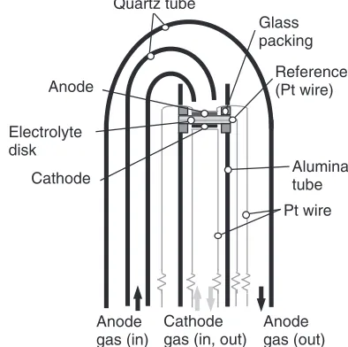
Figure 1 shows the schematic illustration of the apparatus for electrochemical experiment. The sample disk was fixed on the alumina tube with Pyrex glass rings (Thickness= 0.5 mm). The glass ring was melted in situat 950°C to seal the electrode compartments after the sample was assembled in the experimental apparatus. A platinum mesh (80 mesh) with platinum lead wires were used as the current collector for electrodes, and attached to the reference electrode by winding the wire on the rim of the electrolyte disk.
The fuel cell characteristics were evaluated at 600°C. Humidified H2 was introduced to the anode at 30 cm3/min whereas humidified air was introduced to the cathode at 30 cm3/min, respectively. The water vapor pressures of the anode and cathode gases were both p(H2O)=0.019 atm. A DC was sent galvanostatically to the cell to measure the currentvoltage and currentpower density characteristics using a current pulse generator (Nikko Keisoku, NCPG-10-IS). The electrode performance of the cell was evaluated by a
Quartz tube
Reference (Pt wire) Glass packing
Anode
Cathode Aluminatube
Pt wire Electrolyte
disk
Anode gas (in)
Cathode gas (in, out)
Anode gas (out)
[image:2.595.326.523.74.270.2]current interrupt method and AC impedance spectroscopy. Electrode overpotentials were evaluated by a current interrupt method as follows.24)The electric potentials of the anode and cathode against the reference electrode,VAR(j) andVRC(j), were measured as a functions of the current density, j. The overpotentials, defined as the changes in the potentials from those under open circuit condition, consist of electrode reaction polarization,©ARand ©RC, overpotentials due to the changes in hydrogen concentrations were ignored because of the hydrogen partial pressure constant in the measurement, ohmic losses,iRARand iRRC, are shown in eqs. (1) and (2).
VARðjÞ VARð0Þ ¼©ARþiRAR ð1Þ
VRCðjÞ VRCð0Þ ¼ ð©RCþiRRCÞ ð2Þ
The change in potentials of the cell was monitored with an oscilloscope (LeCroy, Wave Surfer 422) when a DC was shut off. AC impedance spectroscopy was measured under open circuit condition using a LCR meter (ZM2375, NF). For the measurement of cathode resistance, LCR meter was con-nected to the 3-electrode cell where a potential was measured between the cathode and reference electrode, while a current
flowed between the anode and cathode. The frequency range was from 100 mHz to 1 MHz.
3. Results and Discussions
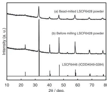
After planetary bead-milling of LSCF6428 with ethanol dispersant and PVP additive, a viscous slurry was obtained. The viscosity was approximately 20 mPa·s at 26°C and originated from the addition of PVP. The milled particles were well-dispersed in the slurry and did not show any aggregation. Figure 2 shows the particle size distribution of LSCF6428 samples before and after planetary bead-milling obtained by DLS measurement. The mean diameter of bead-milled particles was 105 nm and about 3 times smaller than that before milling. These results indicate that the planetary bead-milling reduces the particle size of LSCF6428 powder, and the resulting particles are well dispersed in the ethanol dispersant with PVP. When the milled particles were observed by FE-SEM, the particle size was seen to be less than 100 nm, as shown later in Fig. 5. It seems that the particle size obtained by DLS measurement was affected by PVP which covered the LSCF6428 particles even after ultra-sonication. Figure 3 compares the XRD patterns of LSCF6428 before and after planetary bead-milling. It is seen from thefigure that LSCF6428 maintains its original crystal structure after milling. Peaks in the pattern of the milled specimen are broader than those of the powder before milling. The peak width of the bead-milled powder was broadened to a small extant than that of the powder without milling, suggesting the reduction of the crystallite size. No apparent contaminations such as ZrO2 and other chemical compounds of La, Sr, Co and Fe are recognized in XRD pattern of the milled specimen.
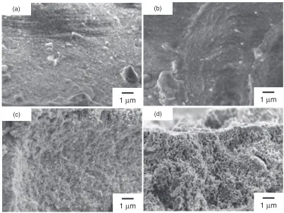
The cross-sectional FE-SEM images of the cathodes after baking at 1150°C are shown in Fig. 4. The cathode made from as-calcined LSCF6428 consisted of particles in the range of 0.25 µm and pores in the same range. On the other hand, the cathode made by planetary bead-milled particles consisted of homogeneous size particles and pores in the
range approximately 100 nm. From the comparison of these SEM images, it is evident that the slurry prepared by planetary bead-milling provides much fine porous electrode structures than the cathode made by solid state reaction method. Figure 5 shows the cross-sectional FE-SEM images of the cathode made by bead-milled LSCF6428 slurry and baked at 300, 600, 950 and 1150°C. The cathode layers look dense in the cases baked at 300 and 600°C, while those baked at 950°C appear to be porous. The particles turned to aggregate with approximately increase in size and porosity at 1150°C. Thermogravimetric analysis of the PVP-containing LSCF6428 is shown in Fig. 6. The weight loss until 400°C was probably caused by decomposition of PVP on the sample surface. The large weight loss between 400 and 500°C can be attributed to the decomposition of PVP within the inter-particle gaps and there by promoting the observed aggrega-tion and increasing porosity. When the baking temperature was increased to 950°C a fine porous structure became visible.
Fuel cells using cathodes prepared with and without planetary bead-milling were constructed and examined at 600°C. Both cathodes were baked at 1150°C to compare the effect of the starting LSCF6428 particles. Currentvoltage (IV) and currentpower density (IP) characteristics of the PCFCs are shown in Fig. 7. The open circuit voltages (OCVs) of the cells using the cathodes prepared from bead-milled LSCF6428 and the as-calcined LSCF6428 are 1.086 and 1.093 V, respectively. The theoretical value of OCV can be calculated by Nernst’s equation and is 1.14 V for the present experimental condition when uniquely conducting electrolyte is assumed. Generally, the proton-conducting perovskites have partial electron hole
conductiv-As-calcined LSCF6428 dmean = 345 nm
Milled LSCF6428 dmean = 105 nm
Milling
Diameter, d / nm
0.1 1 10 100 1000
0 10 20 30
Number
distribution (%)
Fig. 2 The particle diameter distribution of LSCF6428 particles before and after bead milling measured by dynamic light scattering (DLS). Measurements were conducted on slurries diluted with ethanol.
10 20 30 40 50 60 70 80
Intensity (a. u.)
2θ / deg.
(a) Bead-milled LSCF6428 powder
(b) Before milling LSCF6428 powder
LSCF6446 (ICDD#049-0284)
[image:3.595.307.548.72.137.2] [image:3.595.332.517.196.356.2]ity in highp(O2) region,25,26)cathode gas atmosphere in the present case of fuel cell, and the hole conductivity causes the decrease in OCV.27) The obtained OCV was about 0.05 V
lower than 1.14 V and is thus explained by the partial hole conduction. The maximum power density of PCFC with the cathode prepared from milled LSCF6428 was 18.5 mW/cm2.
1 μm 1 μm
1 μm
(a) (b)
(c)
1 μm (d)
Fig. 5 SEM images of the cross sectional structure of the cathode made from bead-milled LSCF6428 slurry after heating at 300°C (a), 600°C (b), 950°C (c) and 1150°C (d).
200 nm (b)
200 nm (d)
2 μm (c)
Cathode
Electrolyte
2 μm (a)
Cathode
[image:4.595.102.498.69.366.2] [image:4.595.96.499.409.712.2]This value was about 6 times higher than the maximum power density of PCFC based on as-calcined LSCF6428 cathode of 3.3 mW/cm2. The cell using the bead-milled LSCF6428 showed higher fuel cell performance than that using as-calcined LSCF6428.
A current interrupt method was applied to separate overpotentials into the contributions from the electrodes and electrolyte resistances. Figure 8 shows ohmic losses of the cells and overpotentials at the anode and cathode. The ohmic loss of the cell using the bead-milled LSCF6428 cathode was decreased by about 6 times from that of the cell using the as-calcined LSCF6428 cathode. The overpotential at the anode was almost the same, and the overpotential of the as-calcined LSCF6428 derived cathode was about 6 times higher than that made from the planetary bead-milled LSCF6428 cathode.
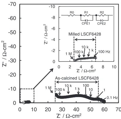
Impedance measured under the open circuit condition shows the same tendency. Figure 9 shows the Nyquist plot of the impedance between cathode and reference electrode. In the plots of as-calcined LSCF6428 cathode, a small dispersion corresponding to the electrolyte in the higher frequency region (1 M-500 kHz) and two semi-circle
corre-sponding to cathode reaction in the lower frequency region (500 k-0.1 Hz) were observed. The electrode resistance was determined using equivalent circuit analysis.28) The spectra werefitted with equivalent circuit in Fig. 9, R0 corresponds to the electrolyte, R1-CPE1 and R2-CPE2 correspond to the cathode. Two semi-circles are assignable to the electrode reactions that referred to the literature.12) R1-CPE1 (500 k-100 Hz) corresponds to the ion transfer of cathode/electrolyte interface and into the cathode bulk, and R2-CPE2 (100 0.1 Hz) corresponds to the oxygen dissociation/adsorption at
30 40 50 60 70 80 90 100
0 100 200 300 400 500 600 700 800 900
W
eight change (%)
Temperature, T / °C
Fig. 6 Thermogravimetry curve of the powder of dried bead-milled LSCF6428 due to 25900°C. The heating rate is 4°C/min which is the same rate of baking the cathode for the fuel cell measurement.
-10 -8 -6 -4 -2 0
0 2 4 6 8 10
-70 -60 -50 -40 -30 -20 -10 0
0 10 20 30 40 50 60 70
Z' / Ω•cm2
Milled LSCF6428
As-calcined LSCF6428
100 k 10 k
1 k 10010 1
0.1 Hz 1 M
100 k 10 k
1 k 100 Hz 1 M
R0 R1 R2
CPE1 CPE2 Z'' / Ω • cm 2 Z'' / Ω • cm 2
Z' / Ω•cm2
Fig. 9 Nyquist plots of cathode resistance of the fuel cell between LSCF6428 electrode and Pt reference electrode measured at 600°C. The partial pressures of gases at the anode side werepH2O¼0:019atm and
pH2¼0:981atm, and those at the cathode side werepH2O¼0:019atm,
pO2¼0:21atm, respectively.
0 5 10 15 20 25 0 0.2 0.4 0.6 0.8 1 1.2
0 20 40 60 80
Power density
,
P
/ mW cm
-2
Cell voltage,
V
/ V
Current density, I / mA cm-2
:Milled LSCF6428 :As-prepared LSCF6428 I-V I-P
Fig. 7 Cell voltages (IV) and power densities (IP) of BCZY622 electrolyte cells with Ni as the anode and LSCF6428 cathodes made from bead-milled and without bead-milling powders measured at 600°C. The partial pressures of gases at the anode side werepH2O¼0:019atm
and pH2¼0:981atm, and those at the cathode side were pH2O¼
0:019atm,pO2¼0:21atm, respectively.
0 0.1 0.2 0.3 0.4
0 20 40 60 80
Current density, I / mA cm-2
0.1 0.2 0.3 0.4 0.2 0.4 0.6 0.8 1 0 0
Ohmic loss, iR
Anode, ηa
Cathode, ηc
:Milled LSCF6428 :As-calcined LSCF6428
Overpotential, η / V Overpotential, η / V Ormic loss, iR / V
Fig. 8 Ohmic losses of the fuel cells and overpotentials of each electrode at 600°C. The partial pressures of gases at the anode side werepH2O¼
0:019atm and pH2¼0:981atm, and those at the cathode side were
[image:5.595.76.260.66.203.2] [image:5.595.335.517.71.324.2] [image:5.595.66.271.260.436.2] [image:5.595.324.528.390.591.2]the cathode surface. As shown in Fig. 9, the resistance of the cathode ascribable to R1-CPE1 made from planetary bead-milled LSCF6428 appears to be markedly smaller than that from the as-calcined powder. However the arc of R2-CPE2 was not able to measure clearly in bead-milled LSCF6428 cathode. For comparison of the resistance ascribable to gas dissociation/adsorption at the cathode surface, it needs to measure the impedance at variety partial pressure of oxygen and water vapor. From these results, it is evident that the use of the planetary bead-milled powder increases the cathode performance. Since LSCF6428 used for the cathode is a mixed conductor of oxide ion and electron, and BCZY622 used as electrolyte is a proton conductor, a triple-phase boundary (TPB) of the cathode, electrolyte and gaseous phases is primarily assumed to be the cathodic reaction site. These results suggest that smaller particle size of LSCF6428, 100 nm in the present case (Fig. 4), are advantageous in increasing the amount of TPB compared to the cathode made of coarse as-calcined LSCF6428. The ohmic resistance was also reduced by the use of the cathode derived from the milled LSCF6428. This fact is explainable by assuming a higher contact area of the cathode/electrolyte interface due to good adhesion of the bead-milled particles to the electrolyte. In total, the use of the planetary bead milling for the preparation of the cathode provides fine porous structure, resulting in good performance of PCFC.
4. Conclusions
LSCF6428 nanoparticles have been successfully prepared by the planetary bead milling method. The electrode prepared from the planetary bead-milled LSCF6428 showsfine porous structure with particle and pore size of about 50 nm. Such an electrode structure resulted in better electrode performance when used with BCZY622 proton conducting electrolyte than the coarse LSCF6428 cathode prepared from as-calcined powder. The lower cathodic overpotential using the milled LSCF6428 can be attributed to the increase in triple phase boundary originated from the small cathode particles in contact with the electrolyte with good adhesion.
The present results suggests possible advantages of the use of bead milling for the preparation of oxide electrodes, i.e., the milledfine powder is effective in establishingfine porous structure and good adhesion between the electrode and electrolyte.
Acknowledgement
This research was supported by Kyushu University Global COE program “Novel Carbon Resource Sciences”.
Interna-tional Institute for Carbon-Neutral Energy Research (WPI-I2CNER) is supported by World Premium International Research Center Initiative (WPI), MEXT, Japan.
REFERENCES
1) H. Iwahara, H. Uchida and S. Tanaka:Solid State Ion.910(1983) 10211025.
2) N. Bonanos, B. Ellis and M. N. Mahmood: Solid State Ion.2830
(1988) 579584.
3) N. Taniguchi, K. Hatoh, J. Niikura, T. Gamo and H. Iwahara:Solid State Ion.5356(1992) 9981003.
4) O. Yamamoto:Electrochim. Acta45(2000) 24232435.
5) A. Mitsui, M. Miyayama and H. Yanagida:Solid State Ion.22(1987) 213217.
6) T. Norby and Y. Larring:Curr. Opin. Solid State Mater. Sci.2(1997) 593599.
7) K. D. Kreuer:Solid State Ion.125(1999) 285302.
8) K. D. Kreuer, S. Adams, W. Münch, A. Fuchs, U. Klock and J. Maier:
Solid State Ion.145(2001) 295306.
9) D. W. Dees, T. D. Claar, T. E. Easler, D. C. Fee and F. C. Mrazek:
J. Electrochem. Soc.134(1987) 21412146.
10) N. Q. Minh:J. Am. Ceram. Soc.76(1993) 563588.
11) L. Yang, C. Zuo, S. Wang, Z. Cheng and M. Liu:Adv. Mater.20(2008) 32803283.
12) S. Ricote, N. Bonanos, P. M. Rørvik and C. Haavik:J. Power Sources
209(2012) 172179.
13) J. Liu, A. C. Co, S. Paulson and V. I. Birss:Solid State Ion.177(2006) 377387.
14) D. La Rosa, M. Lo Faro, G. Monforte, V. Antonucci and A. S. Aricò:
J. Appl. Electrochem.39(2009) 477483.
15) D. Beckel, U. P. Muecke, T. Gyger, G. Florey, A. Infortuna and L. J. Gauckler:Solid State Ion.178(2007) 407415.
16) F. S. Baumann, J. Fleig, H.-U. Habermeier and J. Maier:Solid State Ion.177(2006) 10711081.
17) Y. W. Ju, H. Eto, T. Inagaki, S. Ida and T. Ishihara:Electrochem. Solid-State Lett.13(2010) B139B141.
18) T. Sakai, H. Matsumoto, Y. Sato, J. Hyodo, N. Ito, S. Hashimoto and T. Ishihara:Electorochem.77(2009) 876878.
19) T. Sakai, J. Hyodo, T. Ishihara and H. Matsumoto:J. Ceram. Soc. Japan
120(2012) 3942.
20) H. Oda, T. Yoneda, T. Sakai, Y. Okuyama and H. Matsumoto: Solid State Ion., in press. (doi:10.1016/j.ssi.2013.12.020)
21) H. Y. Tu, Y. Takeda, N. Imanishi and O. Yamamoto:Solid State Ion.
100(1997) 283288.
22) Z. Zhu, Z. Tao, L. Bi and W. Liu:Mater. Res. Bull.45(2010) 1771 1774.
23) L.-W. Tai, M. M. Nasrallah, H. U. Anderson, D. M. Sparlin and S. R. Sehlin:Solid State Ion.76(1995) 273283.
24) H. Matsumoto, T. Shimura, H. Iwahara, T. Higuchi, K. Yahiro, A. Kaimai, T. Kawada and J. Mizusaki:J. Alloy. Compd.408412(2006) 456462.
25) H. Uchida, N. Maeda and H. Iwahara:Solid State Ion.11(1983) 117 124.
26) N. Kurita, N. Fukatsu, K. Ito and T. Ohashi:J. Electrochem. Soc.142
(1995) 15521559.
27) N. Bonanos, K. S. Knight and B. Ellis:Solid State Ion.79(1995) 161 170.