RESEARCH ARTICLE
ENHANCING TEST PATTERN COMPACTION ALGORITHMS FOR SIMPLE TWO
STAGE CIRCUITS
Thamarai, S.M., Kuppusamy, K. and Meyyappan, T
Department of computer science and Engineering, Alagappa University, Karaikudi-630003, Tamilnadu, South India.
ARTICLE INFO ABSTRACT
In this paper, a test pattern compaction algorithms for simple combinational circuits is proposed. It generates test pattern and simulate faults. Fault diagnosis is an important part of failure analysis. The fault diagnosis procedure considered here selects a set of faults and a set of tests. It stores fault simulation results in a fault dictionary and compares dictionary entries against observed faulty behaviors. It adopts fault based test minimization for simple two stage combinational circuits. Proposed Algorithm minimizes the number of test cases based on the number of faults detected. The problem of finding faults and diagnosis consists of two sub problems. The first problem is the determination of possible list of faults. It may include all possible single faults and multiple faults that may occur in a circuit. The second sub problem is minimizing number of tests to be performed to cover all the faults. The job of the proposed algorithm is to find essential tests from all possible test cases. The algorithm is implemented and sample boolean expressions in sum of product forms for sample circuits are experimented. The results obtained are tabulated and plotted. The time and space complexity of the algorithm are measured. From the results, it is observed that the execution time of the algorithm is linear. It increases with the increase in the number of gates in the given circuit. Test reduction upto 99% is observed. The performance of the proposed algorithm is compared with adaptive scheduled fault detection method, and found to be better in terms of reduction in number of tests and processor time it consumes.
INTRODUCTION
A logic circuit, network, or system is a collection of elements put together to perform specified function. Logic circuits fall in two categories: combinational type and sequential type. In combinational type simple logic functions such as AND, OR, NAND, and NOR are performed instantly without time sequence entering into consideration.(Samprakash,1975). Integrated circuit
manufacturers are constantly trying to decrease the number of faulty parts they produce. They analyze parts that fail production tests and determine failure of
each part. It results in improved circuit design or the manufacturing process. Determining the cause of
failure for a circuit is known as failure analysis (Brain Chess, 1995). Failure analysis begins with fault
diagnosis. The objective of fault diagnosis is to form a hypothesis that predicts the physical location of the failure of the chip. A failure analysis engineer uses fault diagnosis results to guide the search for the defect. If the diagnosis is imprecise, the engineer may have an overwhelming physical area to examine (Brain Chess, 1995).
*Corresponding author: [email protected]
Worse yet if the diagnosis is incorrect and the engineer removes the upper layers of the faulty circuit, the actual defect may be destroyed and there will be no way to determine the cause of failure, it is important that a diagnosis be both precise and accurate. Fault diagnosis begins with the selection of a fault model, which describes the behavior of the faults that will be used to explain a faulty circuit behavior. The popular single stuck-at-fault model assumes that the circuit contains a wire that has lost its ability to change values. The wire is stuck-at-1 and stuck-at-0. The single stuck-at fault model is widely used because of its simplicity.
In recent years, the development of integrated circuit technology has accelerated rapidly; MSI and LSI techniques promise to make today’s functional level devices and tomorrow’s basic components. Accordingly, digital systems are built with more and more complexity; the fault testing and diagnosis of digital circuits becomes an important and indispensable part of the manufacturing process. The Integrated circuit fabrication is prone to random defects, which may affect the functionality of a device and cause erroneous outputs. Testing of finished
ISSN: 0975-833X
International Journal of Current Research Vol. 4, pp. 015-019, May, 2010
INTERNATIONAL JOURNAL
OF CURRENT RESEARCH
© Copy Right, IJCR, 2010 Academic Journals. All rights reserved.
Key words:
Combinational circuits, Fault diagnosis, Test cases, Boolean Expressions
Article History:
Received 12rd April, 2010 Received in revised from 15th April, 2010
053 International Journal of Current Research, Vol. 4, pp. 052-053, May, 2010
circuits is essential in weeding out defective parts to ensure that electronic systems built using the ICs function correctly. Sets of test vectors applied to circuits by a tester must have high defect coverage if they are to be effective. Furthermore, since the cost of testing Ics is a significant fraction of the overall manufacturing cost, the time required to test a chip should be minimized. Effective tools for Automatic Test Generation are needed to obtain compact test sets with high defect coverage. In the commercial market, up to 80% of the test costs are due to the analog and mixed signal functions (Kalpana and Gunavathy,2005) that typically occupy around 10% of the chip area which leads to investigation of new testing strategies .Hence there is a necessity to reduce the testing cost (Su and CHO, 1972). The factor that has the biggest impact on testing cost of a chip is the time required to test it. This time can be decreased if the number of tests required to test the chip is reduced. Hence, a test set that is small in size is required.
MATERIALS AND METHODS
A number of basic analytic and heuristic methods namely
fault table method, path sensitizing and equivalent-normal-form(ENF) method, Karnaugh map and tabular method, the ENF karnaugh map method, the Boolean
difference method ,and the SPOOF method are already in
practice.
The fault table method (B. Holdsworth) is the most classic approach to the problem. It is completely general and always yields the minimum set of diagnostic tests. However it suffers from the fact that it requires the very large fault table to be constructed. To overcome the problem of construction of very large fault table, the concept of path sensitizing is introduced. The path sensitizing method (B. Holdsworth) requires no fault table, basically it works only for the class of tree like circuits and special non tree like circuits. Equivalent
normal form(ENF) method is heuristic and systematic
procedure derived from the concept of path sensitizing, (Samuel C.Lee ). Although this method has eliminated the two imperfections that the fault table and path sensitizing methods have, it introduces an unattractive new feature, the requirement of the cumbersome computation of a ‘score function’ for every literal in the ENF and the complemented ENF of the circuit. ENF
Karnaugh map method eliminates the above three short
comings (Samuel C.Lee). This method is the combination of ENF method and the Karnaugh map and tabular method. Both the ENF method and ENF-Karnaugh map method do not guarantee minimal experiments, nor is there a guarantee that a set of sensitized paths can be found for every circuit.
Finally, the boolean difference method and the
SPOOF methodsare two convenient general methods for
deriving tests for detecting any single and/or multiple faults in any part of the circuit without using any fault tables or maps. In Adaptive scheduled test minimization
method, heuristic approach is used for test minimization part. This method, consists of two phases. In the first phase fault table alone is created. In the second phase number of tests is minimized. In this paper, the authors create diagnosing tree by dissecting the fault table matrix into two sub-matrices based on essential test number. The test number is added to essential test set (Thamarai et. al).
Column numbers in these two matrices are added to the root node of the tree as right and left siblings. Left children contains fault-free output column numbers from the matrix (0s) and the right one contains faulty output column numbers from the matrix(1s). The process is repeated until both left and right children results in a single column in them. Essential test set is found after removing redundant test numbers in it.
In Adaptive Scheduled Fault Detection (ASFD) method, each test (input) is applied to the circuit. Application of next test depends on the outcome of the previous test. Test minimization is achieved in this way. The choice of test schedule depends on the outcome of the individual tests in the sequence. A convenient way to present such a sequence of tests and their outcomes is to use a diagnosing tree.
Proposed method
In the proposed method, two tables are generated for the given combinational circuit (boolean expression in sum of products form) namely fault table and fault detection table. It removes the redundancy in test set by grouping test numbers that detect the same fault.. Test numbers detecting single faults are also collected as essential test numbers.
After a digital circuit is designed and built, it is always desirable to know whether the circuit is constructed without any faults. If it is properly constructed and in use, it may be disabled by almost any internal failure. The process of applying tests and determining whether a digital circuit is fault free or not is known as fault detection. If a known relationship exists between the various possible faults and the deviations of output patterns, it is possible to identify the failures and classify them within the smallest set of possible components. This process is termed as fault location. Fault diagnosis is generally referred to as the composite of both the above processes.
The diagnostic techniques of digital systems have progressed from the state of testing the operation codes of the machine instruction set in the early days to the current hardware-assisted software aids for speedy determination and identification of faulty elements. In the Large Scale Integration era, the problem of diagnosis is shifted from locating for faulty discrete component to the identification of replacement module in which faulty component is resident.
procedure to obtain a minimal fixed-scheduled fault-detection test set (experiment) using a fault table consists of the following three steps:
1 .Construction of the fault table 2 .Construction of fault detection table 3. Proposed Algorithm for test minimization
Step 1 : Construction of the fault table
If x1,x2,…..,xn are the input variables to a single output
circuit whose fault-free(correct) output is z = z(x1,…..xn)
and z1,z2,…..zi are the erroneous outputs, each corresponding to one of the possible faults 1,2,….i , a
multiple-output table of the combinations may be obtained:
This is called a fault table, F. The complete test set for any
i is the set of input combinations x j
=(x1 j
,x2 j
……xn j
) such that
z(xj) zi(xj) = 1 for all 1 i l (3.1)
The multiple-output table above may be simplified as follows:
1.Delete the columns that correspond to undetectable faults; that is, delete the columns zi in the table that are identical to z.
2.Combine the columns that correspond to indistinguishable faults; that is, combine the columns zi and zj if zi = zj .
The reduced fault table F* still contains the complete information about the complete test sets for detecting all the detectable faults. In fact, the complete test set for detecting each detectable fault i may be obtained by
taking Exclusive-OR (denoted by the symbol ) operations on column zi with column z as Equation 3.1.
Step 2: Construction of fault detection table
The fault detection table or fault detection matrix GD is
constructed as follows: Each column i , i=1,2,…,l of GD
presents the indistinguishable fault under detection and the entries of the column are obtained from the reduced-fault table by z(xj) zi(xj) .The rows of GD are the input
combinations of the union of all the complete test sets for detecting the faults. If there are m distinguishable faults and the union of all the complete test sets contain p tests, the size of GD is p x m. An entry in row j and column i is
1 if row j is a test for fault i , and is 0 if row j is not a test for fault i. Since there is no need for displaying both the 0’s and 1’s entries in the table GD, it is customary to
display the 1’s only and to leave all the 0 entries blank.
Step 3: Proposed Algorithm for test minimization The first step toward obtaining a minimal test set from a fault-detection table is simplification of the table by deleting certain superfluous rows and columns following the two rules:
RULE 1:
Delete any row whose 1’s all fall in the same columns as the 1’s in some other row. That is, delete any row that is covered by, or is the same as, some other row.
RULE 2 :
Delete any column that has 1’s all the other rows in which another column has 1’s. (Chang,1965).That is, delete any column that covers, or is the same as ,some other column.
These steps may be applied in any order until neither is applicable. The reduced table GD
*
has distinct rows and distinct columns; also, no row covers another row, and no column covers another column. The problem choosing a minimal set of tests that can detect all the faults are discussed in the proposed algorithm. First group 1’s in adjacent rows and column in the fault table. Find the uncovered 1’s in the fault table. Output the test numbers with uncovered 1’’s. Collect test numbers covering the same fault and output one of them. Collect test number covering more than one fault and output the test number. Remove the redundant test numbers incollected output. Complete Algorithm for Fault Detection and Test Minimization
This algorithm accepts the given expression in sum of product form as input. In the first stage, it generates fault table and detects faults. In the Second stage, it determines essential tests after eliminating redundant tests, if any. Proposed method minimizes number of tests to be performed. The pseudocode for proposed Algorithm is s given below:
Step 1: Start
Step 2: Read the input Boolean Expression(Sum of products)
Step 3: Find the number of symbols
Step 4: Find s-a-0 and s-a-1 faults and their expressions Step 5: Eliminate duplicate faults
Step 6: Compute binary combinations Step 7: Apply binary value to fault free output Step 8: Apply binary value to faulty output
Step 9: Evaluate the original expression for the binary combination i and store it in f0
Step 10: Evaluate the i th faulty expression for the binary combination i and store it in fi
Step 11: Find fault detection table fd by comparing f0 and
fi
Step 12: Collect Essential Tests using Proposed Algorithm
Step 12.1: Group adjacent one’s in rows Step 12.2: Group adjacent one’s in columns Step 12.3: Mark the grouped one’s
Step 12.4: Identify the uncovered test numbers
Step 12.5: Identify the test numbers covering the same fault
Step 12.6: Identify the test numbers covering more than one fault
Step 12.7: Eliminate the redundant test numbers Step 13: Display the Essential Tests
Step 14: Stop
RESULTS AND DISCUSSION
The proposed algorithm is implemented in C language and experimented with different boolean expressions. It finds essential test numbers for the given boolean expression. Circuits with two-input And gates are given in Table1. Row
Number x1 x2 … xn z z
1 z
2 … z
i
0 0 0 … 0 0 1 0 … 0
1 0 0 … 1 1 1 0 … 1
. . .
. . .
. . .
. . .
. . .
. . .
. . .
. . .
. . .
. . .
018 International Journal of Current Research, Vol. 4, pp. 015-019, May, 2010
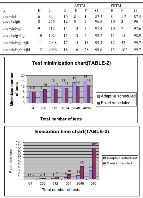
Circuits with And gates having more than two inputs are given in Table 2. The boolean expressions are subjected to proposed algorithm and the results are shown in Table1 and Table2. The results obtained are are plotted to establish the efficiency of the algorithm.
The proposed method achieves high percentage of test minimization in case of gates with lesser input leads than gates with higher input leads. In both cases, Execution time of the Algorithm increases with increase in number of gates. The results are compared with Adaptive scheduled Test Minimization method. Both of these methods, keeps very large fault detection table. This will increase the memory requirement of data structures used. The increase in memory requirement is directly proportional to the total number of inputs to the gates.In the proposed algorithm test minimization varies from 62.5% to 99.7% with the lowest one corresponding to circuit with four gates. In Adaptive scheduled method test minimzation varies from 50% to 99.6% with lowest one corresponding to circuit with four gates.
Legend:
ASTM- Adaptive scheduled test minimization FSTM- Fixed scheduled test minimization A – Boolean expression, B – No. of inputs
C – Total number of inputs D – No. of faults Minimized Tests F – Execution Time in Seconds G – Minimization
TABLE I. (circuits with two input AND gates)
A B C D
ASTM FSTM
E F G E F G
ab+cd 4 16 8 7 0.5 50 6 1 62.5
ab+cd+ef 6 64 11 10 1 82.8 7 1 89
ab+cd+ef+gh 8 256 14 13 2 94.9 9 4 96.5
ab+cd+ef+gh+ij 10 1024 17 15 6 98.5 12 41 99.4
ab+cd+ef+gh+ij+kl 12 4096 20 17 28 99.6 13 113 99.7
Test minimization chart(TABLE-1)
7 10 13 15 17 6 7 9 12 13 0 5 10 15 20
16 64 256 1024 4096
Total number of tests
M in im iz e d nu m b er o f te s
ts Adaptive scheduled
Fixed scheduled
Minimization percentage chart(TABLE-1)
50 82.8 94.9 98.5 99.6 62.5 89
96.5 99.4 99.7
0 5 10 15 20 25 30 35 40 45 50 55 60 65 70 75 80 85 90 95 100
16 64 256 1024 4096
Total number of tests
Mi ni m iz a ti on P e rc e nt a ge Adaptive scheduled Fixed scheduled
TABLE 2.(circuits with more than two inputs)
A B C D
ASTM FSTM
E F G E F G
abc+def 6 64 10 8 1 87.5 8 1.2 87.5
abcd+efgh 8 256 12 8 2 96.8 10 3 96
abc+def+ghi 9 512 14 13 3 97.4 10 7 97.6
abcd+efg+hij 10 1024 15 13 5 98.7 11 15 98.9 abc+def+ghi+jk 11 2048 17 15 13 99.3 12 42 99.7 abc+def+ghi+jkl 12 4096 18 16 28 99.6 13 102 99.7
Test minimization chart(TABLE-2)
8 8
13 13 15
16
8 10
11 12 13
10 0 4 8 12 16 20
64 256 512 1024 2048 4096
Total number of tests
Mi n im ize d n u m b e r o f te s ts Adaptive scheduled Fixed scheduled
Execution time chart(TABLE-2)
1 2 3 5 13
28
1.2 3 7
15 42 102 0 10 20 30 40 50 60 70 80 90 100 110 120
64 256 512 1024 2048 4096
Total number of tests
E x e c u ti on t im e Adaptive scheduled Fixed scheduled CONCLUSION
Results obtained by employing the proposed method can be used to create Fault Library containing fult-free and faulty outputs for essential tests alone. Diagnosing the given circuit essentially involves comparison of fault free and faulty entries in a column of the library. If a value differs in consecutive rows of the same column, then the circuit is diagnosed as faulty. The reamaining essential tests need not be applied. Hence, the proposed method reduces the number of tests to be performed to detect faults. Both methods requires the construction of very large fault table for their working. This procedure is quite simple and easy to apply. The drawback of this method is that it requires a large amount of computer storage space to store the fault table. The next phase of the research work is extended with the development of suitable Genetic Algorithm to overcome the limitation of the proposed method.
REFERENCES
Brain Chess, 1995, Diagnostic test pattern generation and the creation of small fault dictionaries, M.Sc Thesis, University of California, Santa Cruz.
Chang H.Y., 1965 , An Algorithm for selecting an Optimum set of Diagnostic Tests, IEEE Trans. Electron. computers, C-14, pp 706-711.
Holdsworth B, “Digital Logic Design”, Second Edition, Prentice Hall of India.
Kalpana P. and Gunavathy.K, 2005, Fault Oriented Test Pattern Generator for Digital to Analo
converters, Academic Open Journal, C- 13.
[image:4.612.309.540.78.396.2]Samuel, C. Lee, Digital Circuits and logic design, Fourth Edition,Prentice Hall of India.
Su. S.Y.H and CHO. Y.C. 1972, A New Approach to the fault location of combinational circuits, IEEE Trans. on Computers , C-21: 21-36.
Thamarai, SM., Kuppusamy, K. and Meyyappan, T. 2010, Adaptive Scheduled Fault Detection to minimize the number of testcases for simple circuits, proceedings of National conference on Recent Trends in Advanced Energy Materials(NCRTEM-2010), ISBN No.978-93-80400-14-3, 92.