© 2019, IRJET | Impact Factor value: 7.211 | ISO 9001:2008 Certified Journal
| Page 1168
Floating Oscillator based Electric Generator using Mechanical
Energy Harvesting
V Gukan
1, T K Balasekaran
2, E ArunMozhi Devan
3, G Udhaya Kumar
41,2,3
Student, Dept. of EEE, Valliammai Engineering College, Kattankulathur, Tamilnadu, India
4Associate Professor, Dept. of EEE, Valliammai Engineering College, Kattankulathur, Tamilnadu, India
---***---Abstract -
Industries are the major source for thedevelopment of the country. The dramatic increase in population causes the requirement of industries to meet out their basic needs. This increase in industrial civilization causes demand for power to function. For this we need large amount of power generation from different kinds of sources but conventional sources are causing unbalance in the environment by pollution and global warming. To overcome the power demand and production of power in eco-friendly manner, speed breakers are the most efficient sources for the power generation. Since the vehicles count increasing day by day, a large number of vehicles stand in queue at the tollbooth. So, we can utilize the potential energy of vehicles by using speed breakers at regular interval in tollbooth.
Key Words
: Floating magnetic oscillator, renewable
sources, speed breaker power generation, Neodymium
and ferrite magnet.
1. INTRODUCTION
Roadways are the largest and frequently used means of transportation in terrestrial. A large amount of potential energy is wasted at the speed breakers every time when the vehicles pass over it. So, the potential energy of the vehicles can be utilized to generate electricity at the speed breakers. The roller and rack-pinion mechanism use only mechanical parts so the efficiency is lower by frictional losses.
To overcome the frictional losses and gain additional energy and for efficient energy conversion, use of permanent magnet in addition to spring is very much efficient. By using the permanent magnet, we can utilize both kinetic energy of spring and magnetic energy of magnets for electricity production.
In this method, the free-floating magnet between the magnets are responsible for making linear oscillations which is given to the rack and pinion gear which is responsible for converting two-way linear motion into one-way rotation motion. Springs which are impacted by the potential energy of the vehicle are used to transfer the potential energy of the vehicle to the magnetic oscillations. Since the moving parts are of magnetic domain the losses due to friction between the mechanical stationary parts are very much reduced in this method.
[image:1.595.312.557.648.771.2]
Moreover, the linear oscillations are of TO and FRO motion, for making the shaft to rotate in one direction the ratchet and pawl setup is used which is responsible for vehicle and for larger power requirement use of large size magnets with strong magnetic field is advisable. The materials used are made up of nylon which is well suited for medium weight vehicles. But for heavy weight vehicles, it is better to use high strength materials for rack and pinion gears. This paper represents the use of floating magnetic oscillation to produce electrical energy by converting potential energy of the vehicle into kinetic energy and then into electrical energy.
Table 1. Statistics of Indian Roadways
Indian roadways 5603293 km Number of speed
breakers(approx.)
>500000
Average power generated by speed breaker with Floating oscillator
3000W/day
Total power generated in India/day
1500 MW
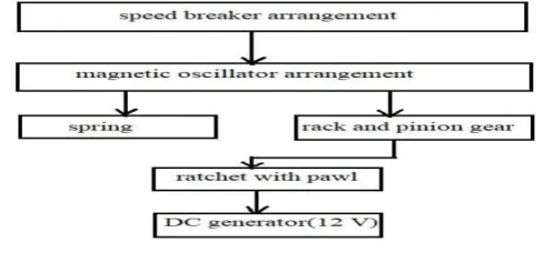
2. BLOCK DIAGRAM OF PROPOSED SYSTEM
© 2019, IRJET | Impact Factor value: 7.211 | ISO 9001:2008 Certified Journal
| Page 1169
Figure.1 Block diagram of Proposed Method3.
ANALYSIS AND DESIGN
3.1
MAGNET
- Length of the magnet = 0.4 inch
A-pole area in inch square = 3.14-inch square - Residual magnetic flux in kilogauss For N42 grade magnet, =13.2 kilogauss
Force due to magnet with contact with a piece of steel in lb
F = 0.58* *
F = 0.58 *(13.2 *13.2) *0.4 * F = 71.649 lb = 32.5 Kg
Force in terms of Newton
F = Mass *Acceleration due to gravity F = 32.5 *9.81
F = 318.819 N
Force exerted by one magnet to another magnet in Newton (F)
F = 318.819 N
Net force acting on the floating magnet = F – force due to weight of the floating magnetic segment + force due to the applied load
= 318.819 – (2 *9.81) + 981 = 1280.199 N
Net force acting on floating magnet =1280.199 N.
3.2
HELICAL SPRING
d – diameter of the spring wire = 8 mm. D – mean coil diameter of the spring = 75 mm. N – number of active turns of spring = 7 turns. W – applied load = 981 N.
G – modulus of rigidity of wire material = 80 GPa.
Axial deflection produced when load applied
ᵟ = =
ᵟ = 70.728 mm
– free length of the spring = 250 mm. – solid length of the spring.
= - - 0.15
= 250 – 70.728 – (0.15 *70.728) = 168.668 mm.
Stiffness of the spring
K = =
= 13.87 N/mm.
3.3
RACK AND GEAR
PINION GEAR
T1 - Number of teeth = 96 teeth
D1 – Diameter of pinion gear = 120 mm
Module = = = 1.25
DRIVEN GEAR
T2 – Number of teeth = 12 teeth D2 – Diameter of driven gear = 15 mm Module = = = 1.25
RACK
Length of the rack = π *D1 = π *120 Length of the rack =376.99 mm.
3.4
SPEED CALCULATION
N1 – Speed of the pinion gear in RPM. N2 – Speed of the driven gear in RPM.
= = = 0.125
N2 = = 160 RPM. (N1 = 20 RPM).
3.5
TORQUE CALCULATION
Torque = force * perpendicular distance (radius of driven gear)
Torque = 981 * 60 mm T = 58.86 Nm.
3.6
POWER OUTPUT
Power produced = Watt P =
P = 986.209 Watt.
4.
CONSTRUCTION
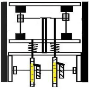
The combination of three upper fixed magnets and lower fixed magnets and floating magnets are called moving arrangement. The upper part of the moving arrangement is connected to the handle for applying force and lower part of it is connected to springs. The upper and lower magnets and floating magnets used here are neodymium magnets with magnetic grade N42. The floating magnets are ring shaped neodymium magnet suspended axially with stainless steel
© 2019, IRJET | Impact Factor value: 7.211 | ISO 9001:2008 Certified Journal
| Page 1170
rod on its axial hole. The three floating magnets are attached [image:3.595.332.540.91.775.2]with wooden rod horizontally through which the rack and pinion mechanism is connected. Initially the floating magnets are made to repel with lower fixed magnets which make them floating. These floating magnets are made to be fixed in desired position by stands connected to the sidewalls at the time of moving arrangement moves downwards. The pinion gear and ratchet are connected with shaft which is fixed at sidewalls by ball bearings through which DC generator set is connected through shaft.
Figure 2. 2D construction details with three floating magnets
5.
WORKING
When the vehicle passes over the speed breaker setup, the force is applied on the handle (Figure 3). The moving arrangement attached to the handle which also moves downwards causes the spring to compress while the floating magnet is kept stationary with the help of stands attached to sidewalls. Immediately after the vehicle passing, the spring expands with massive force which is impact on the floating magnet during the lower fixed magnets repel the floating magnet with massive force (Figure 4). At that time floating magnet make oscillations (TO and FRO motion) which given to the rack through which the pinion gear along with ratchet rotates (Figure 5). The ratchet which convert the two-way linear motion into one-way rotational motion of the DC generator set. After several oscillations the floating magnet comes to the initial position (Figure 6).
[image:3.595.341.528.108.298.2]Overall the potential energy of the vehicle is first converted into kinetic energy of floating magnetic oscillation arrangement. Then the kinetic energy of magnetic oscillation and compression of springs are converted into mechanical energy by rack and pinion gear mechanism. Then the speed is multiplied by compound gear setup. Then the mechanical energy is converted into electrical energy by DC generator.
Figure 3. phase 1
Figure 4. phase 2
[image:3.595.40.295.235.420.2]© 2019, IRJET | Impact Factor value: 7.211 | ISO 9001:2008 Certified Journal
| Page 1171
Figure 6. phase 4
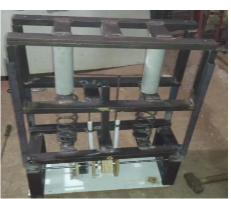
Figure 7. Experimental setup
6.
RESULT ANALYSIS
Table 2. Result Analysis
SI NO LOAD (Kg) OUTPUT POWER
FOR ONE CROSSING(W)
1 50 55
2 100 121
3 150 210
4 200 250
Thus, these experiments conclude that, if load increases
then the spring deflection is maximum for which the
mechanical energy (rotation of pinion gear) is
increased. Thus, the electrical energy increases as
potential energy (weight of the vehicle) is increased.
The electrical energy is also proportional to the speed
of the vehicle through which it passes the
experimental setup.
7.
COMPARISON WITH PREVIOUS SPEED BREAKER
MECHANISM
SI NO
PARAMET ERS
RACK-PINION METHOD
FLOATING OSCILLATOR 1 Efficiency Moderate High 2 Shaft
rotation
Low High
3 Design Moderate Moderate
4 Weight impact
Spring Spring
5 Cost Moderate Moderate
6 Maintenan ce
More required Less required
8.
CONCLUSION
Availability of sources (potential energy of the vehicle) is free of cost and enormous. Hence this project is very much useful to obtain power from ever available energy from the vehicles. Even though the cost of the Neodymium magnet is little higher, by considering its importance in the future electricity development, it is better to implement in roadways and gets benefited. The development of electric vehicles is rapidly increasing, so by implementing it we can provide the electric energy necessary for the electric vehicle by energy from the vehicle itself.