1
Designing a Smart Rainwater Buffer
Bachelor thesis for Creative Technology by Boaz Vetter
BSc Project Report 5-8-2017
Supervisor: Ir.ing. R.G.A. Bults Critical observer: Ir. J. Scholten Faculty of EEMCS
2
Abstract
3
Acknowledgements
I would like to thank several people that helped or supported me during this project. First of all, I would like to thank my supervisor, Richard Bults. Richard has given me lots of advice and feedback throughout the span of this project. His hands-on approach helped me during development of my prototypes.
Secondly, I would like to thank Hendrik-Jan Teekens. He was my contact person at the municipality of Enschede, who visited the campus of the University of Twente countless times to provide feedback on this project.
4
Table of Contents
Abstract ... 2
Acknowledgements ... 3
1 Introduction ... 6
2 State of the Art ... 7
2.1 Problem analysis ... 7
2.2 Rainwater harvesting advantages... 9
2.3 Literature research method ... 9
2.4 Currently available solutions ... 10
2.5 Infiltration systems ... 11
2.6 Buffering systems... 13
2.7 Concluding problem analysis and literature review ... 18
2.8 Novelty of the research question ... 18
3 Methods and techniques ... 19
3.1 Creative Technology Design Process ... 19
3.2 Requirements Elicitation ... 20
3.3 MoSCoW ... 20
3.4 Stakeholder Analysis ... 21
3.5 Concept generation ... 21
3.6 iPact analysis ... 21
3.7 Demonstrating the prototypes ... 22
3.8 Evaluation ... 22
4 Ideation... 23
4.1 Stakeholder identification and analysis ... 23
4.2 Functional and non-functional requirements ... 24
4.3 Concepts ... 25
4.4 Conclusion ... 29
4.5 iPACT analysis ... 30
5 Specification ... 32
5.1 Proposed setup ... 32
5.2 Functional Architecture ... 35
5.3 Specifying the prototypes ... 36
5
6 Realization ... 40
6.1 Decomposition of system components ... 40
6.2 Development of lo-fi prototype 1 ... 40
6.3 Development of lo-fi prototype 2 ... 42
6.4 Development of hi-fi prototype 3 ... 43
6.5 Development of hi-fi prototype 4 ... 46
7 Evaluation and Discussion ... 47
7.1 Functional and non-functional requirements evaluation ... 47
7.2 Feedback on prototype ... 48
8 Conclusion ... 50
9 Recommendations ... 51
10 References ... 52
11 Appendices ... 54
Appendix A – Map displaying locations extreme runoff ... 54
Appendix B – Results brainstorm session ... 55
Appendix C – Baseline and satellite stakeholders... 56
Appendix D – Material list ... 57
Appendix E – Smart Rainwater Buffer python code ... 58
6
1
Introduction
Last year’s Little Prince’s Day main theme has been about flooding [1]. The heaviest downpours based on the most recent KNMI prediction models for 2050 have already occurred prematurely [2]. The past ten years the water boards have invested 1,5 billion euros to fight stormwater runoff, but it has become clear an extra effort has to be made from other parties: the municipality and the inhabitants of their cities.
With its 160,000 inhabitants Enschede is the urban heart of East Netherlands. The
geographical situation in Enschede makes rainwater management a daunting task. Enschede lays on a moraine, has been built on a hill and the area has been paved through the years. Due to these factors, in weather conditions with a large volume of rainfall in a short time the strain on the existing sewerage system of the city of Enschede is too high. At spikes of heavy rainfall over time, parts of the city might flood as result. The geographical factors inducing flooding are further elaborated on in chapter 2.
Stormwater runoff causes damage and health hazards directly to the inhabitants situated in lower areas, to shops and to the municipality. Appendix A shows the area with stormwater runoff in the streets as well as some of the most extreme flooded areas at yearly peak rainfall moments in Enschede. The municipality of Enschede targeted a problem area, marked purple on this map. The municipality reached out to the University of Twente to design a solution for this expanding problem. The main focus lies primarily on providing a smart solution for large volume rainwater buffering in the aforementioned target area of the Oldenzaalsestraat, which has a surface runoff of roughly 7.000 m3 of rainwater. The main research question for this project is defined as:
“How to develop a rainwater buffering system that reduces the strain on the sewerage system of Enschede and is distributed over the premises of its inhabitants?”
7
2
State of the Art
In this chapter, the causes of flooding specific to the city of Enschede are analysed. Relevant buffering- and infiltration systems are explored in order to understand currently available solutions, including their advantages and disadvantages.
2.1 Problem analysis
The origin of flooding in the city can be attributed to Enschede’s geographical and
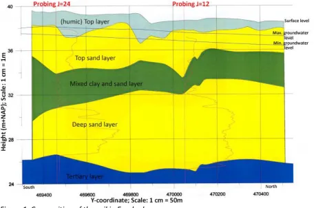
[image:7.595.71.531.234.536.2]morphological situation. Enschede is situated on a moraine: the land was pushed up by big chunks of land ice in the glacial age. This implies that Enschede lies on mixed soil as shown in figure 1.
Figure 1: Composition of the soil in Enschede
Soil, at the surface level consists of mixed ground: fine sand, a layer of loam, raw sand, and a layer of clay. This poorly pervious deep clay layer is situated at a depth of 12 to 20 meters [3]. Depicted in figure 1, the probed bearing capacity of the soil has a measured coefficient of friction of J=12 or J=24. It can be concluded that Enschede’s soil is rather impervious, considering clay usually has a coefficient higher than 5, and peat has a coefficient of over 8. As a result of impervious soil, Enschede has problems with high ground water levels. This contributes to material damage due to flooding [4]. This factor not only contributes to contextualizing the problem, but also shows that the soil of Enschede is not ideal for water buffering systems relying on infiltration systems.
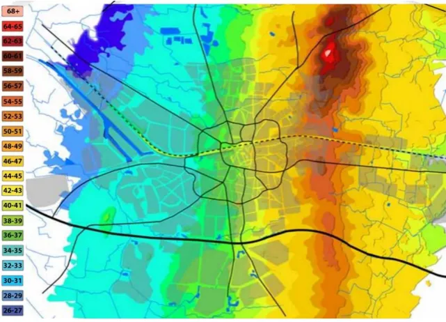
8 depicted in figure 2. Because of the high amount of paved surface area, not all the water gets absorbed into the soil during peak rainfall moments.
[image:8.595.73.394.197.428.2]The altitude at which the city of Enschede is built also contributes to the risk of water runoff in particular areas. Figure 2 shows a height map of Enschede. The eastern part of the city is roughly 44 meters higher compared to the lowest part of Enschede in the west. This slope in the city causes water to naturally flow and settle towards the western area of Enschede, making it a high-risk zone for floods.
Figure 2: Height map of Enschede indicated in metres
Stormwater runoff causes significant negative impact to homeowners, the municipality of Enschede and (insurance) companies. Aside from property damage, urban stormwater runoff increases health risks to homeowners and inhabitants. Damage of property includes seal cracks or damage in foundation walls, windows, doors, basement flood damages, loss of irreplaceable items or plumbing failures [6]. Moreover, stormwater runoff erodes soil, ditches and stream channels leading to degraded water quality. As a result, aquatic habitats in nearby ecosystems can be adversely altered [7, 8, 9]. Lastly, stormwater runoff carries continued mobility issues for vulnerable areas of Enschede.
Appendix A shows a map of Enschede with the problem areas during heavy downpour marked. Red indicates water inside the houses of residents and companies. As it can be seen on the map, more than half of Enschede’s streets are flooded during a storm. The only areas not flooded are the areas not in the center and the higher-up eastern area of
Enschede. The focus for this project is on the area of the “Oldenzaalsestraat”, marked purple on the map. An interview with the client showed that in this area, during a TS100-situation1, approximately 7.000 cubic meters of surface runoff floods the streets.
Rainfall is expected to be more extreme than in the past, leading to more cases of flooding with material damage as a result [10]. The goal in this project is to think of a buffering
9 solution for this problem. The surface of the targeted area comprises 154 hectares.
Interviews with the client showed that roughly two-thirds of this area has been paved, which means about 100 hectares is paved. A solution has to be created that goes beyond the existing sewerage system as it is incredibly expensive to replace [11, 12]. Currently, every 70 years the sewerage system is replaced. The last time Enschede replaced its sewage system was 40 years ago, therefore with 30 years to go a more time-efficient solution needs to be employed.
2.2 Rainwater harvesting advantages
The first and foremost important aspect of buffering rainwater in Enschede is to reduce the threat of runoff. However, buffering rainwater is also an environmentally conscious action and can save the inhabitant of Enschede on their monthly water bill. Figure 3 shows a possible reduction in use of sanitized water by up to 57% [10], by reusing rainwater for different purposes in and around the house.
Figure 3: Sanitized water reduction [10]
2.3 Literature research method
In the following section, literature review is performed to explore the design space of relevant stormwater management solutions. Literature research terms were elicited by performing a brainstorm session and by conducting semi-structured interviews with the client.
10
Figure 4: Wordcloud displaying used key words in literature research
The matrix method of literature was a popular research method in the domain of health sciences [13]. This literature review method has been adapted since (R. Klopper et. Al, 2007), known as the concept matrix. The latter method was used in this project as the concept matrix is more flexible from an epistemological point of view, which benefits problem-based research in other domains where knowledge is of a conscious incompetence. The goal of literature review using this matrix is to refine knowledge on the subject, present to the reader a clear idea of the nature context of this research, to convince the reader of knowledge in the field and lastly to build a case for the empirical part of this study. 2.4 Currently available solutions
This section introduces and explores solutions that are currently employed in tackling
11 Concepts References St or m w at e r / R ain w at e r / R ain fa ll H om e ow n e r D ra in ag e In fil tr at ion H ar ve st in g / Buf fe rin g / R e te n tion R u n of f / O ve rfl ow / Fl oo d in g P e rm e ab ilit y / Fi lte r / P or ou s Soi l P av e d / P av e m e n t G ar d e n / P ar cel U rb an iza tion / R e si d e n tia l (L ID ) L ow Im p act D e v. C ist e rn / T an k / Ba rr e l R oo f(t op ) W at e r m an ag e m e n t St or m W at e r M an ag e m e n t M od e l
(Trieu et al., 2000) X X X X X X X
(Smullen et al., 2005)*
X X X X X X
(Litofsky et al., 2014)
X X X X X X
(Steffen et al., 2013)
X X X X X X X X
(Jennings et al., 2012)
X X X X X X X X X X
(Chenevey and Buchberger, 2013)
X X X X X X X X
(Schlüter and Jefferies, 2004)
X X X X X X
(Scholz, 2015) X X X
(Monaghan et al., 2016)
X X X X X
(Sandink, 2015) X X X X X X
(Jennings and Baker, 2015)
[image:11.595.26.578.67.597.2]X X X X X X X X X X x
Figure 5: Conceptual checklist matrix showing literature with overlap 2.5 Infiltration systems
12 Permeable Pavement Systems (PPS)
Permeable pavement systems (PPS) use a base and subbase of sustainable materials that allow water to flow through this surface. An example is depicted in figure 6. These systems are designed not only to reduce runoff, but also filter pollutants from the water.
Figure 6: Grass concrete tiles: a form of permeable pavement system
Even though PPS are designed to collect and infiltrate surface runoff to support recharge of groundwater levels, PPS can be used solely for storm management purposes as well. These systems are cost-efficient, easily mouldable to tailor needs and have been applied in a wide variety of places. Permeable Pavement Systems can be found in car parking lots, on roads and other public spaces. However, such a system heavily relies on the permeability of the soil, therefore, it is not a suitable solution for Enschede
As a part of the European Union’s climate adaptation project, Dutch, Flemish and British governments started an international cooperation project, Sponge2020. The goal and ambition of this project is to make densely populated cities fully capture or infiltrate all the rainwater. As a result of this project the municipality of Rotterdam installed a very similar system to the permeable pavement system: water buffering street tiles in Rotterdam’s Agniese neighbourhood [16]. These permeable tiles allow water to pass through but instead of letting the water infiltrate, the tiles capture and buffer the rainwater. Installing a similar system would be a possible solution to tackle the intrinsic disability of Enschede’s soil to absorb water.
Infiltration Gallery
13
Figure 7: Schematic illustration of a residential infiltration gallery used to reduce stormwater runoff [17]
As can be seen in figure 7, the residential downspout is connected to a sub-surface perforated pipe. This pipe is situated in an infiltration medium, which also functions as a buffer. Lastly the overflow of this gallery setup leads to a storm sewer. One advantage of this system is the low-key nature of this system; it is placed below the surface which means there are no aesthetical drawbacks. Albeit more powerful, this system also relies on a
relatively permeable yard soil. Such a system is ineffective in soil types comprised of clay and peat [18], therefore this is not an applicable solution in Enschede given its impermeable soil. Furthermore, this system requires digging out a garden to install it, which results in high installation costs and an inability to perform maintenance.
2.6 Buffering systems
Buffering systems can be used as an alternative to infiltration systems. These types of solution allow for the collection of rainwater. In rainwater harvesting scenarios for
stormwater management benefits, the larger the volume of the buffering cistern, the higher the stormwater control potential [19]. Therefore, volume capacity is an important factor when looking at these types of systems.
Downspout disconnection system
14
Figure 8: A connected downspout versus a disconnected downspout
One advantage of such a system is the moderate cost, but many home owners are reluctant to install such a system because this often merely shifts the problem: after heavy downpour, the home owner might be left with wet yards or leakage and mouldy basements [20]. Applicability to homes in Enschede and urbanized areas in general is limited. In the past decades, it became a trend for home owners in urban environments in The Netherlands to pave their garden with bricks, stones or other impermeable material, making this system unusable. Moreover, this system requires intervention of the homeowner. In case of heavy storm, the homeowner would need to switch the downspout manually once the garden is saturated, making it not an ideal or smart solution.
An intelligent disconnected downspout system was designed in 2015 by a group of Creative Technology students of the University of Twente called the Enskéton during a 24-hour brainstorm competition. This is essentially a smart disconnected downspout system that checks the local weather forecast and empties itself before heavy rainfall [21]. Such a system can be cost-efficient and controllable, but lacks high buffering capacity.
Stormwater ponds
15
Figure 9: Example of a stormwater pond in West Seattle, United States
According to Monaghan et al. [7], local residents’ receptivity to such a system depends on age, attitude about water quality and whether their home is adjacent to a pond. It was concluded that awareness of the ecological function of stormwater ponds is present, however merely knowing this was not enough to convince homeowners to adopt such a system. Furthermore, homeowners seemed unwilling to go against the social norms of landscaping. These ponds are not a viable option as most home owners are not situated nearby a pond. A similar solution would be for farmers to create separation ditches that are able to temporarily buffer in cases of overland flow. However, both of these systems would only be applicable in the outskirts of Enschede. Furthermore, it is important to take note that homeowners are not seeking an intrusive system that might negatively alter the opinion that neighbours have of them [7].
Green roof
Green roofing is a hot topic in the Netherlands right now, and is promoted from various municipalities. Considered a hybrid buffering and infiltration solution, a green roof consists of a thin layer of substrate with a good buffering capacity, respectively covered by a layer of plants. About 50% of the rainwater can be buffered by this soil and it is eventually
16
Figure 10: Model of a series of apartments with a green roof installed
Green roofing is sometimes applied to houses with an angled rooftop, but is considered highly inefficient because it loses its buffering function. On a flat roof, this is an effective solution, however there are considerable disadvantages to such a system. Because a green roof system weighs a lot, often modifications need to be made to a roof structure to improve the carrying capacity before it can be installed. A green roof also requires regular maintenance and safety modifications for the gardener that maintains these roofs [23]. Overall, the installation and maintenance of green roofs comes with substantial costs. Homeowners that do choose to install a green roof system often receive subsidy [24], lowering installation costs. The limited applicability makes this system unsuitable for the problem area in Enschede targeted by the municipality.
Water fence
This system is a commercial product which functions by redirecting water that pours on the roof to a hollow fence through the downspout and allows for its retaining [25]. Developed with the purpose of storing water in dry areas, hollow fences can also be used as buffering elements to capture and store storm runoff. Figure 11 shows an example of a hollow fence.
[image:16.595.73.264.559.746.2]
17 It is estimated that the service area of the average downspout includes 50% of the total roof area [26, 27]. This solution can be applied to any household with a garden without much effort. Furthermore, installation and maintenance costs are relatively low. However, this system is unsuited for stormwater management purposes unless water is allowed to flow out of the fence in case of overflow. The disadvantage of this system is the fact that it needs to be able to let water out, which can be tackled by implementing an intelligent system that empties the buffer when it’s full.
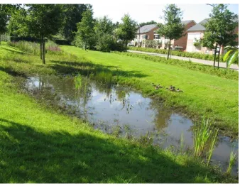
Wadi
[image:17.595.71.410.271.533.2]A wadi is a mixed buffering and infiltration system designed in Enschede [28]. Wadis comprise of a grassy area, situated lower than the environment which retains water and a connection to this area. Water is often transported to a wadi using sewerage pipes. Figure 12 shows a wadi in action.
Figure 12: A wadi retaining water in Enschede
Water captured by a wadi infiltrates in the soil or water is transported to surface area water located nearby. A wadi is a sustainable system, as it prevents clean water to be transported to a sanitation facility. A wadi cannot be implemented on the premise of Enschede’s
18 2.7 Concluding problem analysis and literature review
Periodically, the strain on the sewerage system of the city is too high. Impermeable soil and the gardens of homeowners commonly being paved make the infiltration solutions explored in this chapter unsuitable for the city of Enschede. Existing buffering solutions are either not applicable to premises of inhabitants, are tough to implement or simply do not provide the buffering capacity required to solve the problems during downpour.
The Enskéton does not buffer nearly enough runoff to be applied, however it has the added value of being an intelligent solution that responds to external factors. On the other hand, the water fence has a higher buffering capacity but it lacks intelligence to function as a resilient adaptive system, as it does not have the means to let water flow out autonomously. Buffering water captured from a disconnected downspout in underground basins is effective but requires a considerable amount of labour to implement.
2.8 Novelty of the research question
The analysis of the problem leads to the goal of this project. This project aims to bridge the gap in research and practical work by offering a smart solution to flooding caused by rainwater. Thus, the research question for this project is formulated as follows:
“How to develop a rainwater buffering system that reduces the strain on the sewerage
system of Enschede and is distributed over the premises of its inhabitants?”
In conclusion, it can be said that the main research question is novel, considering no
19
3
Methods and techniques
This section describes methods and techniques used in the ideation, specification, realization and evaluation phases of this project.
3.1 Creative Technology Design Process
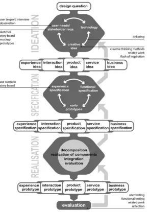
[image:19.595.77.368.232.648.2]The creative technology design process [29] served as a guideline for this graduation project in terms of planning, implementation and documentation. As can be seen in figure 13, this design process consists of four larger phases: Ideation, Specification, Realization and Evaluation. These four phases are further elaborated on, in chapter 4 to 7 in this report.
Figure 13: Illustration of the Creative Technology design process
The general design question of this project was determined through initial interviews with the municipality and the regional water authorities and an intensive technological
background research, found in chapter 2 – State of the Art.
20 brain storm sessions and concept generation, a design idea was decided on in the ideation phase (chapter 4). To converge, the five most promising ideas have been visualized and presented to the municipality of Enschede, which then chose a single idea to elaborate on. This convergent phase set the transition point to the specification phase.
In the specification phase, a number of low-fidelity (lo-fi) and high-fidelity (hi-fi) prototypes has been made to explore the design space, and realise a feedback loop through a short evaluation with the client and relevant stakeholders.
In the ideation phase, system requirements, stakeholder elicitation and a PACT analysis are described, following a description of the realization of the prototypes mentioned in the specification phase. Next, these prototypes are presented to the client, the municipality of Enschede. Based on this assessment and evaluation, changes might have to be made, features discarded or improved upon, resulting into a transition into a high-fidelity prototype.
A high-fidelity (hi-fi) prototype is built in the realization phase (chapter 6) using proven methods of engineering design. Iterative and incremental development was used to design and improve this prototype, allowing for backtracking in the case of faulty decisions. Initial evaluation should show whether the end product met the specification.
In the evaluation phase, functional testing and user testing is performed to assess whether the final prototype meets the system requirements.
3.2 Requirements Elicitation
Both functional and non-functional requirements for the intended system have been collected using two methods and techniques: interviews and literature research.
Multiple interviews with the most important stakeholders led to a draft of the functional and non-functional requirements. The most important stakeholders for eliciting these
requirements are listed in the influence-interest matrix under chapter 4 - stakeholder analysis.
These stakeholders are: the municipality of Enschede, regional water authorities Vechtstromen and the University of Twente. The most important requirements of the system are reliability, low-maintanance, low cost in that particular order as specified by the client.
Several system requirements have been listed as a result of literature research, described in chapter 2 – State of the Art. Additionally, the author gave his expert opinion in the field to set clear boundary conditions and add requirements that were deemed missing after performing aforementioned methods for requirements elicitation.
3.3 MoSCoW
21 this project are divided in one of the following categories, in order of importance.
Must have: Non-negotiable critical must-have attributes or features. Even if one must-have requirement is not included, the project delivery should be considered a failure.
Should have: Important and if possible, these features should be included.
Could have: Less critical, “nice to have” features that could be added to improve user experience or satisfaction.
Won’t have: Least critical, lowest payback attributes, or ‘Would like to have in the future’.
After eliciting the initial functional and non-functional requirements in chapter 4 – Ideation, system requirements have first been re-evaluated by means of review and expert opinion and, following this, subdivided in order of importance using the MoSCoW method in chapter 5 – specification.
3.4 Stakeholder Analysis
The development of a new product for a client starts with a good understanding of the requirements for this product. Requirements elicitation is the process of making explicit the (latent) requirements for a new product preferably with their priorities. However,
requirements elicitation may not be limited to the client, there may be more parties involved in the development process.
Every party (including the client) involved in the requirements elicitation process is a stakeholder. The challenge is to identify stakeholders relevant for the development of the product. Therefore, we adopt the stakeholder identification in the requirements engineering process from Sharp et al. [31].
3.5 Concept generation
Two brainstorm sessions were performed by the author to think of as many concepts as possible. The author chose to use the technique of making mind maps, to explore the design space using associations that branch off from a central idea. This map can be found in appendix B. Brainstorming as a way of concept generation defers judgment and reaches for divergence, stimulating idea generation and creativity.
Next, in order to diverge, the author made a choice to narrow down the concepts to five concepts. These concepts were drawn digitally as mock-ups, as visualizing concepts helps create a clear mental image. Moreover, it is a powerful tool to convey ideas during concept presentations to the client.
3.6 iPact analysis
An iPACT analysis was made in order to work out a typical user perspective scenario, considering Intended use, People, Activities, Context and Technology [32, 33].
22 Technology describes the features of the technology and how the users will interact with the technology.
3.7 Demonstrating the prototypes
Demonstrations of the system were split up in two parts. First, the system is shown running in the background, which showed the system in an equilibrium situation. Secondly, a run-through of the system in an emergency situation was presented. In this scenario, heavy rainfall is expected and the system will adjust itself accordingly. Only 50 litres of water will be discharged by the system to simulate how it works.
3.8 Evaluation
Evaluation is performed using client and stakeholder feedback from demonstrating the final prototype of the intended system, and by assessing the functional and non-functional
23
4
Ideation
Chapter 2 – State of the Art concludes there is a need for a novel system that can buffer rainwater, that reduces the strain on the existing sewerage system of Enschede and is also distributed over the premises of its inhabitants.Methods include setting (preliminary) requirements, brainstorms, visualizing concepts, decision making through the use of interviews and lastly an iPACT analysis.
4.1 Stakeholder identification and analysis
The influence and interest analysis of each stakeholder in this project have been analysed using an interest-influence matrix, shown in figure 13. The inhabitants of Enschede are rated highest in terms of influence and interest because these end-users are to operate and maintain the intended system. The primary contact person from the municipality of
[image:23.595.74.513.369.637.2]Enschede is Hendrik-Jan Teekens. Meetings with the client showed that the municipality has plans to use financial stimuli in the form of subsidy or lower taxes to the inhabitants of Enschede in order to encourage the adoption of the intended system, therefore they are rated high on terms of influence. As they are the initiators of this project, with responsibility of solving the problem of regular stormwater runoff, the municipality scores maximum on the scale of interest.
Figure 13: Influence-interest matrix showing roles of different stakeholders in this project
24 4.2 Functional and non-functional requirements
As described in chapter 3 – Methods and Techniques, these preliminary requirements have been elicited as a result of interviews and literature review. System requirements have been split in two categories: functional requirements and non-functional requirements. In the second iteration of system requirements, listed in chapter 5 – specification, requirements will also be categorised in order of importance using the MoSCoW method [34].
Functional requirements
-The system should be able to buffer rainwater -The system should be automatically regulated
-The system should be able to empty the buffer autonomously
-The system should be able to handle a throughput of a least 2000 litres per hour (see specification)
-The system should be modular
-The system should be adjustable from a distance
-The system should drain buffered rainwater without the possibility of damaging land or property
Non-functional requirements -The system should be scalable
-The system should be weather proof (ip65+) -The system should be durable
-The system should require low maintenance -The system should be economically efficient
-The system should control the water flow using valves
-The system should use make use of a network in order to receive weather updates and to be regulated externally
-The system should buffer rainwater without leaking -The system should be able to control water flow
25 4.3 Concepts
Before developing concepts, a two-part brainstorm session took place. The result of this brainstorm can be found in Appendix B. Next, five of these brain storm ideas have been developed into concepts. These concepts are further described in this section.
[image:25.595.70.526.152.525.2]4.3.1 Garden sponge
Figure 14: First concept, displaying a garden holding a massive sponge
26 4.3.2 Emergency balloon
Figure 15: Second concept, inspired by the idea of a foldable party-tent
Figure 15 describes the second concept. This second concept shows a portable, deployable solution in the form of an inverse party tent that buffers rain water.
Right before or during expected downpour this foldable system can be taken out of the shed and quickly set-up. The design is similar to a party tent, with a rubber material that stretches under the pressure of the water weight that it catches. The basic construction consists of four poles, a rubber material in between and a tap at the middle or bottom of the material. The advantage is that this solution is cheap and doesn’t require any adaptation or space.
27 4.3.3 Hollow plastic trees
Figure 16: Third concept, displaying an artificial tree that harvests water
Figure 16 displays a plastic three that uses the width of its branches to harvest water. An assortment of hollow plastic trees and bushes can be placed in the garden which catch rainwater. A fake tree with branches that reach out and a thick hollow base can store a substantial amount of water. Water flows from the branches, hanging plants and other type of real plants can be hung from the branches of the hollow tree which also absorb some of the water and might give the tree more of a natural appeal.
28 4.3.4 ”Bed of nails” buffering tiles
Figure 17: Fourth concept, displaying concept buffering tiles in two conditions: down and up
Figure 17 shows tiles that buffer rainwater. These tiles have nine retractable elements that pop up in times of heavy rainfall. This way, the garden can be submerged in water, but homeowners can still walk in their garden by stepping on these yellow elements.
These yellow elements are plastic elements able to withstand force, as they are meant for walking on. A requirement is for the garden to have a border around the outer edge of the tiles, to be able to submerge the tiles. The tiles have holes in the bottom for the buffered water to infiltrate into the soil after a downpour.
29 4.3.5 Smart Rainwater Buffer
Figure 18: Fifth concept, displaying a garden with buffering elements in the form of a fence and plant holders, and a control system near the downspout
A final concept is displayed in figure 18. This is a modular system which buffers water that falls on the roof of a house in containers with different shapes. A core element is the hollow fence. Elements can be linked together to create one big buffer. Ponds, garden furniture, bases for plants, hollow trees can all be connected to this system. The intelligence for this system is within the automated regulation at the downspout.
Instead of a standard-sized wooden fence, a hollow fence can be placed with the same dimensions between the industry standard pillars already present on the premise. Each fence element with standard dimensions of 14x180x180 can buffer roughly 450 litres of water. Using solely fence elements, the average garden of 40 square meter could hold up to 4050 litres of water.
4.4 Conclusion
30 4.5 iPACT analysis
As described in 3 – Methods and Techniques, an iPACT analysis has been applied to demonstrate a typical use case scenario in the intended context.
Figure 19 displays an iPACT analysis for the intended system. “People” have been described by comparing house prices in Enschede. It can be concluded the average household consists of a family from middle to upper-middle class. “Activities” has been described by looking at system functionality. “Context” has been described by looking at houses in the targeted problem area, marked purple in appendix A. The typical home in this targeted area is either a terraced house or a semidetached house with an average garden size of 40 square meters. This lower area in Enschede has been defined by the municipality of Enschede because there’s a large runoff of 7000 m³ during heavy downpour. Using google maps it has been determined these houses mainly have pointy roofs. “Technology” has been described from the end-user perspective in this scenario.
Scenario Type Use case scenario Rationale
This scenario has been developed as a part of the design process of this thesis. It is intended to give a rich description of a general context use case scenario of the proposed Smart Rainwater Buffer (SRB) system. The intention of this system is to buffer rainwater, in order to reduce stress on the existing sewerage system during times of peak rainfall. Homeowners in targeted problem areas in Enschede experience damage to property and safety hazards during a downpour. Homeowners are looking for a solution on their property which is not intrusive to their garden. Moreover, homeowners might appreciate the possibility of living more sustainable: tapping buffered rainwater to water the plants or the car.
PACT analysis
People – A starter family of four in their mid-thirties, well educated, able-bodied. The family members are not technically inclined, but know how to operate a computer and smartphone.
Activities - Using the system to buffer all the rainwater that falls on their roof during the heaviest downpour of the year. Then, buffered rainwater is used to water the garden. Context – Living in the Willem Alexanderstraat in Enschede. This area is well-known to have had issues with water flooding the streets periodically in the past, because this street is situated in a lower part of Enschede. Their garden measures 8 by 5 meters, about the same as their neighbours’ garden. They have a pointy roof with a downspout in the front and in the backyard. An industry-standard wooden fence shields off the backyard from outsiders.
Scenario title
31 Technology – The Smart Rainwater Buffer (SRB) envisaged as a standalone system that requires little to no interaction to function properly.
At the core of the intended system is a controller that autonomously opens and closes the buffer by means of a valve, based on the weather forecast. The homeowner can interact with the intended system in several ways: he can remotely empty the buffer from a pc or tablet, he can manually open the side taps of the buffer to water the plants and lastly, he can set the idle water threshold – the amount of water stored for gardening purposes. Scenario
Petra and Jos are a couple in their mid-thirties with a daughter of eleven and a son of eight. Petra is a social worker and Jos is a teacher of a high school. They live in a problem area concerning rainfall in Enschede, the Willem Alexanderstraat. They moved there five years ago and every year they had problems with stormwater runoff into their house. This year they decided to purchase the Smart Rainwater Buffer (SRB), which Jos placed himself on a Saturday afternoon. It was a relatively easy job: the fencing slats slid right into the existing concrete fencing base poles. He then needed to cut the existing downspout off to connect to the new hollow fencing system to finish installation. In autumn, the heaviest downpour of the year hit Enschede. The SRB emptied itself beforehand with an electrical valve and automatically buffered half the water that fell on their roof during the
downpour, a registered 1800 litres. Petra and Jos weren’t alone in purchasing this system, a lot of neighbours of Petra and Jos purchased the SRB this year. The neighbourhood was surprised to notice the streets weren’t flooded this time. In the days after, Petra and Jos’ system slowly releases 1600 litres of water back to the sewerage system, leaving 300 litres of water for Jos and Petra to water the plants.
32
5
Specification
In chapter 4 – Ideation one concept of an intended system has been chosen by the client. In this chapter, this concept is further analysed and elaborated upon by proposing a setup with functional design, including system specifications. Then two iterations of a lo-fi prototype will be discussed, transcending into two high-fi prototypes later.
5.1 Proposed setup
An outline of the proposed setup is given below in a bottom-up approach. Choices for individual elements and their dimensions are discussed in this section. Client interviews pointed out that the proposed solution has to be functional, require low maintenance and be cost-effective.
[image:32.595.71.399.396.654.2]The standard measurement for a concrete fencing slat base pole in the Netherlands is 10x10 centimetres [36]. The standard measurement of a fencing slat is 180 cm x 180 cm [37]. Figure 20 shows the dimensions of the proposed fencing element. An inner diameter of 14 centimetres was chosen. Consecutive fencing elements connect to each other with a 3.2 cm pipe on the bottom side. The maximum buffering capacity per element consists of 450 litres per fencing slat element. The material used will be plastic. Material thickness and strength of material has to be further researched. An inner diameter of 14 centimetres is determined to ensure high buffering capacity whilst not taking lots of space.
Figure 20: Dimensions of a single fencing element
33 openly at the bottom side, allowing water to flow through. Water levels will be even. An advantage of parallel over cascaded is the fact that only one valve is required, whereas every cascaded element needs to have an own valve, in order to let water out.
[image:33.595.95.350.289.585.2]The client decided the system would need to be engineered in a parallel-type fashion because cascading would require too much maintenance and the system would be more error-prone in a cascaded setup in case of congestion. Moreover, the costs of a cascaded system would be significantly higher because of the requirement of a separate valve for every element. A cascaded system does not allow for water to flow back into the sewerage system. The suggestion was made by the client not to use any valves but to use narrow-diameter pipes that have a low throughput, which will dump the water back into the sewerage system over time. This suggestion was made to keep the system reliable. This is not considered viable because control of water flow out of the system is lost without a valve.
Figure 21: Cascaded versus Parallel fencing setup
34
Figure 22: Typical setup in a 40 square metre backyard
An estimation has been made that determined there’s roughly 3500 parcels in this area. Using satellite pictures in google maps, an estimation has been made for the average surface area of the roofs of the houses in the aforementioned problem area. Using these satellite images 50 different roofs of resident houses in the area Oldenzaalsestraat have been measured, and average out to roughly 70 m² per roof per house with a backyard. Interviews with the client showed there’s a surface runoff of 7000 m³ of water in this problem area during the heaviest downpour of last year. In order to buffer all this water, 28,5 litres of water per m² of roof surface would have to be buffered. If all houses in this area would need to buffer all this water, the average house with a roof of 70 m² should buffer 2 m³ or 2000 litres of water during occurrence of extreme downpour. This is made given the assumption that rain falls straight down, without the influence of wind.
Predictions from the municipality of Enschede show that in a situation with an occurrence of T = 100, once in the hundred years, there’s a downpour of 40mm in Enschede in 75 minutes time. The total amount of water that will fall on the roofs in this problem area in this period of 75 minutes is (70*3500) * 0,04 = 9.800 m³ of water. Per average roof of 70 m² this is 2800 litres of water.
In conclusion, it can be said the throughput of the valves need to be able to handle at least 2800 litres per 75 minutes, or 2240 litres per hour.
Throughput
35 Throughput Kv [38] is defined as: 𝐾𝑣 = √𝑄(𝑙 𝑝𝑒𝑟 𝑚𝑖𝑛𝑢𝑡𝑒)
𝐹𝑔𝑙 ×𝐹𝑠𝑔
With Q as the wanted volumetric throughput measured in l/min, Fgl as the throughput factor for water and Fsg as the relative density. The desired minimum throughput is 33,33 litres per minute, which relates to a minimum diameter of at least 13mm. A diameter of 13mm will be able to handle a throughput of 3000 litres per hour at a pressure of 1 bar. Because at this width the leads could easily clog with dirt, a minimum width of 30mm is desired. Choosing this width will ensure the leads won’t get clogged easily.
Filtering
To minimalize the chance of clogging and to reduce maintenance intervals, filtering of the rainwater is a necessity. A coarse filter is placed on the existing downspout to filter out larger dirt such as leaves. Secondly, a fine filter of 500 micrometres is proposed to filter out the smaller dirt [39].
5.2 Functional Architecture
[image:35.595.72.463.390.566.2]In order to get a clear understanding of the intended functioning of the system, two decomposition layers have been made. Figure 23 shows the functional architecture of this system as a ‘black box’. The forecast data and system setup data are inputs, as well as end-user and administrator overrides, and the system outputs effectuation in the form of valve actuation, posting of performance data and error messages.
Figure 23: Decomposition level 0 of the functional architecture of the Smart Rainwater Buffer
Figure 24 zooms one level deeper on the functional architecture of the system, opening up the black box.
Starting on the left-hand side: Precipitation data is pulled by the rainForecastReceiver function. This function calculates how many litres of rainwater are expected in the buffer in the next two hours. Next, this processed precipitation data is sent to the bufferLogic
function.
36 controlling function called bufferController. The bufferController then effectuates this
decision.
[image:36.595.35.560.185.408.2]System performance data is sent from the bufferLogic to the user and officialities. The users and officialities can override the bufferLogic decision making in order to force immediate effectuation the bufferController, opening the valves. Users can also configure their system and send system setup data to the bufferLogic.
Figure 24: Decomposition level 1 of the functional architecture of the Smart Rainwater Buffer
5.3 Specifying the prototypes
Through iterative prototyping, additional system requirements were obtained. This section starts by describes specification, a short evaluation and additional system requirements for each prototype. Then, a second iteration of the functional and non-functional requirements of the intended system can be specified.
Prototype 1: Lo-fi
This initial prototype focuses on the requirement of measuring the input and releasing the buffered water in a controlled way. In order to realize this controlled feedback loop. A buffer to retain the water is required. Secondly, a sensor is required to measure the water level. Thirdly, a controllable valve should be placed as low as possible in the buffer. Lastly, a controller to regulate the system. In order to get a good understanding of the functionality and problems that arise, it is suggested to use a large buffer.
An Additional requirement that resulted from the presentation of this prototype to the client and supervisor:
37 Prototype 2: Lo-fi
Prototype 2 is a continuation of prototype 1. An overview of the result of prototype 1 can be seen in chapter 6 – Realization. Added functionality to the system include fetching local rain predictions based on a T+120 minutes model. The number of litres of rain expected in the buffer are calculated based on the location of the SRB prototype and roof surface. Raw SRB performance data is output on a terminal window.
Additional requirements that resulted from the presentation of this prototype: FR 1 – The system should calculate the optimal time for discharging rainwater FR 2 – The system must monitor buffered water temperature
FR 3 – The system must display legionella warnings to the user
FR 4 – The system should display system performance data which includes water level and water temperature
FR 5 – The system should be able to discharge rainwater in the garden as well as back into the sewerage system
FR 6 – The system should display the water level in percentages
FR 7 – System error notifications should be displayed to the user through the interface FR 8 – The system should have a physical button that allows discharging of buffered water Prototype 3: Hi-fi
In this third iteration, a dashboard was implemented to display system performance data to the end-user in a more meaningful way. Water level in the buffer is displayed visually in percentages. To realize this, a webserver is required.
Additional requirements that resulted from the presentation of this prototype: FR 1 – The system must use wireless connectivity to fetch data and broadcast a web interface
FR 2 – The system should automatically discharge water in the buffer after extended periods of high water temperature
Prototype 4: Hi-fi
38 5.4 Requirements, second iteration
Preliminary system requirements have been described in chapter 4 – Ideation. Additional requirements emerged during the development of these four prototypes, and have been added to the list. Requirements categorized using the MoSCoW method [34], as described in chapter 3 – Methods and Techniques.
5.4.1 Non-functional requirements Should have
NFR1 The system should be modular NFR2 The system should be scalable
NFR3 The system should require low maintenance
NFR4 Monitoring data displayed by the system should be presented in a meaningful way to the end-user
NFR5 The system should use wireless connectivity to fetch data and broadcast a web interface
NFR6 The system should display performance data using a webserver NFR7 The system should display the water level in percentages
Could have
NFR8 The system could be robust
NFR9 The system could be economically efficient
NFR10 The system could buffer rainwater without leaking NFR11 The system could be able to control water flow rate NFR12 The system could have additional manually operated taps
NFR13 System error notifications could be displayed to the user through the interface Won’t have
NFR14 The system won’t have a built-in infiltration solution
NFR15 The system won’t make use of the LoRa network [34] to communicate 5.4.2 Functional requirements
Must have
FR1 The system must be able to buffer rain water
FR2 The system must be able to empty buffered water autonomously FR3 The system must be automatically regulated
FR4 The system must be weather proof (ip54+)
FR5 The system must drain buffered rainwater without the possibility of damaging land or property
FR6 The system must monitor buffered water temperature FR7 The system must display legionella warnings to the user
FR8 The system must have a physical button that allows discharging of buffered water FR9 The system must automatically discharge water in the buffer after extended
39 FR10 The system must display system performance data which includes water level and
water temperature Should have
FR11 The system should be able to handle a throughput of a least 2000 litres per hour FR12 The system should be adjustable from a distance
FR13 The system should use make use of a network in order to receive weather updates and to be regulated externally
FR14 The system should filter dirt and rubbish from the water before buffering
FR15 The system should be able to discharge rainwater in the garden as well as back into the sewerage system
40
6
Realization
This section starts with a decomposition of system components, including materials used. Next, a description of the development of each prototype is given, with a small evaluation after the realization of every prototype.
6.1 Decomposition of system components
A decomposition step was taken to analyse necessary system components.
After researching different existing valve types, three different two-way valve types are considered. Butterfly valves are the industry standard in large fluid control applications, but are better suited for use in tubes with a large diameter. Another option is a magnetic
solenoid valve, these valves are cost-efficient albeit sensitive to dirt or other kinds of pollution. It is not feasible to completely filter out all dirt in the system, therefore this valve might perform worse over time. A third option is the use of ball valves, these seem more suited as these are applicable to narrow pipes. Ball valves become costly as the diameter increases, but a small diameter of half an inch allows for a high enough flow rate at 1 bar. A ball valve is more insensitive to dirt pollution, a ball valve will be used in the product. The choice of controller is a Raspberry pi, as these are powerful, cost-efficient and have an on-board general-purpose input/output (GPIO) interface. An Arduino is not considered because this lo-fi prototype is to merge into a hi-fi prototype which includes running a webserver in a later stage. Author’s experience teaches that Arduino microcontrollers often run into problems when hosting webservers concurrently with other continuous tasks. The programming language of choice is Python because of wide availability of libraries and ease of use in combination with GPIO-based applications.
The proposed sensor for measuring the water level is a waterproof ultrasonic sensor. Other options include measuring the liquid levels through capacitive sensing or a float sensor, but the choice was made for an ultrasonic sensor because this should be more reliable; less sensitive to errors as a result of accumulation of dirt and algae to it compared to a float sensor, and less unpredictable and error-prone than a capacitive liquid sensor.
6.2 Development of lo-fi prototype 1
The focus for development of this prototype was on the hardware setup. Figure 19 shows a picture of the building process. TheØ 32mm PVC tube on the top hand side was placed as high up as possible, slightly next to the middle of the buffer – an Intermediate Bulk
Container (IBC). An IBC was chosen because of the large buffering capacity and low cost. This was done to ensure a water tight seal with the rubber of the connections to the high-density polyethylene. The electrical ball valve, displayed in figure 18, was attached to the Ø 2” tap using a combination of a brass ½” to ¾” converter and three polypropylene connectors up to 2”.
41 and bolts. This ultrasonic distance sensor sends a 5v signal on the output (echo), so a voltage divider with resistor values of 1k and 2k Ohm was used to lower the voltage coming into the raspberry pi to roughly 3.3. volt, not to damage the raspberry pi. The buffer was connected to the existing 75mm downspout with a simple rain filler. By means of experiment, it was estimated that less than 20% of the water going through the downspout got harvested by the system.
Figure 25: Fitting the valve
42 This prototype has been presented to the client and the supervisor of this project. This first prototype was successful, as it was able to measure current water level and control the water level within a proof-of-concept setting on the campus of the University of Twente. Feedback was given by the client and supervisor to represent the output data of the system in a more meaningful way, and to average out readings to increase accuracy.
6.3 Development of lo-fi prototype 2
The system uses a rain barrel filler to fill the buffer. Rainwater harvested by this filler flows through a pipe, perpendicular to the downspout, into the buffer. If the buffer is full, water flows from the buffer to the downspout back into the sewerage system. The problem of low water harvesting power of the system was addressed in this prototype. Improvements on accuracy and stability of ultrasonic sensor readings were made by averaging 3
[image:42.595.72.387.387.731.2]measurements. The original downspout was 5mm smaller than the connector of the rain barrel filler. The Ø 75mm downspout had to be converted to Ø 80mm in order to fit the rain barrel filler. However, because of this 5mm gap at the conversion, water flowing down created a vortex towards the middle. This vortex lead to water falling through the middle instead of the side of the rain pipe. In turn, this lead to rainwater not being captured by the rain barrel filer. Figure 27 shows the solution: a converter (1) with a slanted inside, bridging a diameter of 75mm to a connection piece of 80mm (2). Furthermore, the system was made leak-proof.
43 As described in 5 – Specification, this prototype needed to fetch the local rain precipitation forecast data. This was realized using python to read out Buienradars’ GPSGadget app [40], which displays the precipitation forecast data for the T+120 minutes for the set GPS
coordinates expressed in an integer value between 0 and 256. In order to assess the accuracy of this data, a program was written in python to log the data. During times of logging, it was not uncommon to read out precipitation forecast values over 200, as high as ‘226’. Using the following formula provided by Buienradar [41], the expected rainfall in mm per hour can be calculated. In this example, 226 is used for ‘value’:
Precipitation Intensity = 10^((value-109)/32) = 4532 mm/hour.
At low rain intensities, the prediction model is fairly accurate. However, it was found that at high values, the inaccuracy raises dramatically. The example above displays this inaccuracy. For this system to function properly, it is key to have readings as accurate as possible. A solution to this problem is proposed in chapter 9 – Future work.
Expected rain is now displayed to the user in a more meaningful way by showing the calculated expected litres in the buffer in the next two hours, and by displaying the leftover water in the buffer expressed in litres. This is displayed later on this chapter, in figure 30. This version was presented to the client, Regional Water Board Vechtstromen and the supervisor. During this presentation, the suggestion was made by stakeholder Regional Water Board Vechtstromen to think of other ways to discharge a surplus in rainwater. They proposed to automatically discharge rainwater in the garden in winter instead of the sewerage system because of the low groundwater level during winter. Another point of attention was the possibility of the development of legionella if the temperature of the buffered water is too high for extended periods. The system should host a webserver locally in order to function completely autonomously
6.4 Development of hi-fi prototype 3
To realize displaying performance data to the end-user, implementation of a webserver was required. This has been realized using the python-based Flask microframework [42]. Real-time link between running python code is then realized using the Jinja2 template engine [43] to send back and forth data from html to running python code. Prototype 2 is then merged into this framework on a separate thread to keep the system running both tasks
concurrently. The system also has a waterproof physical override button, so the user can now tap water out of the system to water the plants or wash the car. Furthermore, a waterproof temperature sensor was added to monitor water temperature.
44
Figure 28: Different sensors attached to the IBC
Subsequently, a clamp had to be developed for the electronics enclosure. This building process is illustrated in figure 22. Additionally, a water-proof button was added on the side of the electronics enclosure for the end-user to discharge water from the system to their garden.
The system code of the lo-fi prototype was then integrated step-by-step. In order for the webserver to run concurrently with measurement of sensors, these functions are run on a separate thread. Additionally, code was added to monitor the water temperature
periodically. The python code for this system can be found in Appendix E.
45
46
Figure 30: Simple web interface on the Smart Rainwater Buffer
6.5 Development of hi-fi prototype 4
[image:46.595.73.255.554.746.2]In the last prototype, it was key to make the system more compact. During demonstrations, the system had a variety of cables running out to connect to a monitor, keyboard, mouse, power source, sensors, ethernet cable. The electronics of the system have been fit in the enclosure, displayed in figure 31. Instead of over ethernet, the system now uses wireless connectivity. All electronics have been enclosed in a waterproof IP-67 casing. The only external wires required are two power cables. The system uses cronjobs to automatically start on system boot. The power source is now to a smaller USB-type power supply instead of a bulky laboratory power supply. Appendix D shows a list of the used materials and their costs in the last hi-fi prototype.
47
7
Evaluation and Discussion
The evaluation of the product consists of two phases. First, all requirements have been tested in a demonstration setting to assess the system. Secondly, documented feedback on the final prototype by stakeholders was elicited.
7.1 Functional and non-functional requirements evaluation
System functionality has been assessed during a demonstration by addressing each
component of the functional and non-functional requirements individually. Figure 32 and 33 show the results of this evaluation session.
Functional Requirements
ID Function Compliant? Comments
FR1 Does the system buffer rainwater? Yes
FR2 Does the system empty buffered water autonomously? Yes
FR3 Is the system automatically regulated? Yes
FR4 Is the system weather proof? (IP54+) Yes*
Ultrasonic dist. sensor is not water-proof, different sensor is suggested
FR5
Does the system discharge water without the possibility
of damaging property? Yes Water flows back into the sewerage system
FR6 Does the system monitor water temperature? Yes
FR7
Does the system have a physical button that allows
discharging buffered water? Yes
FR8
Can the system handle a throughput of at least 2000
litres per hour? Yes
FR9 Is the system adjustable from a distance? No
Roof surface can be configured but does not affect system
FR10
Does the system make use of a network to receive
weather updates? Yes
FR11
Does the system calculate the optimal time for
discharging rainwater? Yes Empties two hours prior to a downpour
FR12 Does the system filter dirt and rubbish? Yes Only a coarse filter is applied
FR13 Does the system warn when maintenance is required? No
FR14
Does water get discharged after periods of high
temperature? No The temperature is only measured
FR15
Can the system discharge water into the garden as well
as the sewerage system? No
FR16 Is this system able to control water flow rate? No
FR17 Is it possible to operate the system manually? Yes Tactile push button on the side
FR18
Are system error notifications displayed through the
[image:47.595.35.574.220.747.2]web interface? No
48
Non-functional Requirements
ID Function Compliant? Comments
NFR1 Is the system modular? Yes
NFR2 Is the system scalable? Yes Can connect to any buffer
NFR3 Is the system economically efficient? -
No research performed; costs of prototype
under €500
NFR4 Does the system require low maintenance? No Not tested yet for extended periods
NFR5 Is monitoring data diplayed in a meaningful way? Yes Visual aid shows the water level
NFR6 Is the system robust? No Not tested yet for extended periods
[image:48.595.28.573.70.286.2]NFR7 Does the system buffer rainwater without leaking? Yes
Figure 33: Assessment of functional requirements of the SRB
7.2 Feedback on prototype
This final prototype has been presented to the municipality Enschede, the chairman of the Water Board, the supervisor and critical observer.
Informational poster
As a tool to explain this system to stakeholders from different backgrounds, an informational poster was designed. This poster can be found in Appendix F. This poster explains the
functioning of the system through the use of a MADE loop [44]: Monitoring, Analysis, Decision and Effectuation. An explanation of the system was given to the stakeholders by combining a cognitive walkthrough scenario and the MADE loop presented in this poster. Interviews
The critical observer of this project questioned why this system is designed to make use of a rain barrel filler instead of two pipes that lead 100% of the water through the pipes in the buffer. In a test session, it was estimated roughly two-thirds of the rainwater to be
harvested by the system. The most important reason for designing the system with a rain barrel filler is safety. If the system happens to clog with the proposed alternative, the existing downspout will fill up with water until it reaches the roof. This could cause water damage when the system is implemented in a context with a flat roof, like on the University of Twente. Moreover, designing the system to run 100% of the rainwater through the buffer will make it clog more frequently, requiring more maintenance.
The chairman of Water Board Vechtstromen pointed to the fact the sewerage system needs to be able to vent air. This is a non-issue the way the system is currently designed, because the downspout is always ‘open’ through the middle. With the proposed setup by the critical observer in the last paragraph this would be a problem however, which could be resolved by using a bleeder valve. This puts an extra requirement on the end-user to perform
49 The client asked to elaborate on the design choice of this valve opposed to a cheaper
alternative. As mentioned in chapter 5 – Specification, cheaper valves such as magnetic solenoid valves work less reliable when exposed to liquids polluted with dirt. One of the systems requirements is not to leak water, therefore a reliable valve was required.
What happens when the garden is not perfectly straight, and the buffering elements in the back of the garden are situated lower than the one next to the downspout? This comment was made by a representative of the municipality of Enschede. A water pump placed at the lower part with a second pipe on the bottom side back to the sewer would need to be added to solve this problem, or a second valve at the end which slowly releases to infiltrate in the soil.
The client warned for health hazards during the presentation of prototype 3: when rainwater is exposed to warm weather (>23C) for prolonged periods, the legionella bacteria could develop [45]. Legionella has a health risk if contaminated or evaporated water is inhaled or taken in by humans. The bacteria could spread when watering the plants with buffered water. To counter this, a temperature sensor has been added. The buffer should empty itself after prolonged water temperatures of over 23 degrees.
Vechtstromen also enquired about possibilities regarding infiltrating water automatically in the soil instead of discharging buffered water back into the sewerage system. During winter, the groundwater level is low. Though not added in the current setup, this feature could be added by adding a second 2-way valve, or replacing the existing 2-way valve with a 4-way 270-degree valve.
50
8
Conclusion
In this chapter, an answer will be given to the main research question. The goal of this project was to develop an intelligent solution for large volume rainwater buffering during heavy rainfall that reduces the strain on the existing sewerage system in the city of Enschede.
Through an iterative process of generating ideas, specifying, realizing and evaluating, also known as the Creative Technology Design Process, a system has been proposed to the client whilst carefully accounting for all stakeholders in this project. Multiple functional prototypes have been presented to the client, the municipality of Enschede. The result is an intelligent weather-aware buffering system that empties itself before heavy rainfall. This system is placed in the garden of house owners and, by connecting to the downspout, utilizes roof surface to harvest rainwater.
As a proof-of-concept, the system works. In the future, a different type of ultrasonic distance sensor should be used. Type HC-SR04 is very sensitive to small disruptions, and functions unreliably. Fetched weather data has showed exponential inaccuracy as values for precipitation forecast data go up. To combat the problem of low ground water levels in Enschede in winter, the system could be redesigned to automatically discharge rainwater in the soil. Long-term testing is required to assess system performance and stability over periods of time. This is recommended prior to starting a pilot study.
The main research question is: “How to develop a rainwater buffering system that reduces
the strain on the sewerage system of Enschede and is distributed over the premises of its
inhabitants?”


![Figure 7: Schematic illustration of a residential infiltration gallery used to reduce stormwater runoff [17]](https://thumb-us.123doks.com/thumbv2/123dok_us/9758935.476924/13.595.73.525.68.324/figure-schematic-illustration-residential-infiltration-gallery-reduce-stormwater.webp)