Intuitive Impedance Modulation in Haptic Control
using Electromyography
K.J. (Kees) van Teeffelen
MSc Report
C
e
Dr.ir. J.F. Broenink
Dr.ir. D. Dresscher
Dr. A.H. Mader
Dr.ir. W. Van Dijk
January 2018
001RAM2018
Robotics and Mechatronics
EE-Math-CS
University of Twente
i
Preface
This thesis was written to conclude the graduation period of the Master of Science programme in Systems and Control at the University of Twente in Enschede, the Netherlands. The presen-ted work was execupresen-ted within the joint innovation centre i-Botics, a collaboration between TNO and the University of Twente.
During the execution of the presented research I had the pleasure of combining work within the Robotics and Mechatronics group (RaM) of the University of Twente with a part time in-ternship at TNO in Leiden, the Netherlands. This combination offered me additional learning opportunities and great chances for my future career as a robotics engineer.
I would like to thank my daily supervisors, Dr. ir. Douwe Dresscher of the University of Twente and Dr. ir. Wietse van Dijk of TNO for guiding me through the process of my graduation project and for presenting me with all the help and feedback I needed to successfully complete this thesis. Furthermore, I would like to thank all others involved with RaM, TNO and i-Botics in particular that expressed interest in my research and offered to help me in any way, shape or form. Finally, I would like to thank all of the volunteers that participated in the experiments. Thanks to them I was able to collect insightful data that supports the claims of my research.
I hope you enjoy reading this thesis.
Kees van Teeffelen
iii
Summary
The research presented in this thesis focusses on the haptic control of a robotic teleoperation system. In this system, a KUKA LWR4+ robotic arm (slave device) is remotely controlled by a human operator through a Force Dimension omega.7 haptic device (master device). Besides encoding its position, this haptic device is able to apply force feedback to the operator.
To connect the robotic master and slave devices, an impedance controller is used. This imped-ance controller can be interpreted as a virtual spring of which the ends are attached to the end effectors of the master and slave devices. The effectiveness of motion tracking and the success-fulness of creating the desired interaction with a remote environment is summarised as the level of transparency of the system. The stiffness setting of the impedance controller is closely related to both the transparency and stability levels of the system. Although a stiff connection could in theory create a very transparent interaction between the two devices, stability can be-come an issue especially when communication delays are present between the two devices. By guaranteeing that all energy that is used by the controller is either added by the operator or the remote environment, stability can be guaranteed through the passivity theorem.
Keeping the transparency and stability properties of the system in mind, there does not seem to be an ideal stiffness setting for the impedance controller. Stability problems can harm the transparency level of the system which can for instance lead to high control efforts or a shak-ing behaviour of the robotic devices. For this reason, this research focusses on modulatshak-ing the impedance controller through muscle activation information of the human operator. These activation levels are captured using a Myo Gesture Control Armband, which creates an estim-ate of the muscle activation levels using electromyography. To goal is to creestim-ate a teleoperation system that uses impedance modulation in an intuitive way, which should increase the effect-iveness of the task execution by the human operator.
The impedance controller is designed using a PF architecture, meaning that the master control-ler sends information on the master’s position to the slave controlcontrol-ler, while the slave controlcontrol-ler sends back the forces computed by the impedance controller based on the relative position of both devices. This position and force information is sent over the communication channel, in which a delay can be added to simulate communication over a distance.
From the muscle activation data, an estimate of the co-contraction level in the human arm is created. This is the level of simultaneous activation of flexor and extensor muscle pairs, in which the position and the force application by the human arm do not change but the stiff-ness of the elbow joint is increased. These levels are calibrated to indicate a normalised co-contraction level between zero and one, after which the signal is low-pass filtered to extract the frequencies of interest. This normalised co-contraction level is then used as a scaling factor to scale the settings of the impedance controller.
The master and slave controllers both contain a transparency layer and a stability layer. In the transparency layer, variables are exchanged with the communication channel and the master and slave devices to which they are directly connected. On the slave side, the position informa-tion of both devices is used to compute forces that will be applied by the impedance controller. This is the force that is sent back to the master device to be applied here as well. The stability layers use an energy-based monitoring approach to make sure no energy is added by the con-troller, known as energy leaking. This is the effects that can cause destabilisation of the devices which increases for increasing time delays in the communication channel.
communication channel, co-contraction estimation and Gazebo simulation are all implemen-ted on one PC using ROS.
Hypotheses are included that focus on the expected behaviour of the system and the human operators. Co-contraction behaviour is expected to increase when carrying out a positioning accuracy task with respect to a task in which careful interaction with the remote environment is the main goal. Furthermore, during time delayed communication a decrease in stability is expected to result in a decrease in transparency, which can show as the mentioned shaking behaviour of the devices and the increase of controller efforts, harming the safety level of the system and its environment. Finally, it is expected that the designed impedance modulation approach will enable the operator to create a variable stiffness level of the controller which will correspond to the requirements of the conducted tasks.
Experiments were designed to validate the functional design of the system and to get an indic-ation of static friction levels in the KUKA hardware. Furthermore, experiments were done in which ten inexperienced test subjects volunteered to execute tasks using the simulated KUKA model. These tasks included a task of positioning accuracy, while moving in between and paus-ing on setpoints, and a task of careful interaction in which control efforts were to be minimised during an impact situation. During these experiments, relatively low and high constant imped-ance settings were tested versus the designed variable impedimped-ance setting that scaled between these low and high impedance levels. The test subjects were never aware of their ability to change the impedance level of the controller through their muscle activation to test the intuit-iveness of the design.
The functionality experiments confirmed the expectations, showing a fully functional control-ler when implemented on the simulated model but a large decrease in functionality when the KUKA hardware was used. This indeed seems to be the result of quite significant friction present in the joints of the hardware. From the data that was gather during the experiments with test subjects, is was seen that the co-contraction behaviour showed the expected results, creating a stiffer connection between the master and slave devices during the accuracy exper-iment than during the impact experexper-iment. This resulted in a combination of good results in both the accuracy and impact experiments, creating relatively low positioning errors and low controller efforts. The constant low and high impedance settings performed relatively good during some of the experiments but never during both the accuracy and the impact experi-ment.
v
Contents
1 Introduction 1
1.1 Context . . . 1
1.2 Problem statement . . . 1
1.3 Related work . . . 2
1.4 Research goal . . . 3
1.5 Overview . . . 3
2 Background 5 2.1 Teleoperation control . . . 5
2.2 Available hardware and software . . . 6
3 Analysis 11 3.1 Teleoperation system outline . . . 11
3.2 Transparency . . . 11
3.3 Stability . . . 16
3.4 Variable impedance control based on human motor behaviour . . . 20
3.5 Estimation of human impedance levels . . . 21
3.6 Hypotheses . . . 24
4 Design 27 4.1 Estimation of co-contraction levels . . . 27
4.2 Outline of master and slave controllers . . . 30
4.3 Transparency layer . . . 31
4.4 Stability layer . . . 33
4.5 Kinematic and dynamic KUKA models . . . 40
4.6 Quantifying parameter settings . . . 42
4.7 Implementation . . . 44
5 Experiments 47 5.1 Validating the functional design . . . 47
5.2 Indication of static friction levels in the KUKA hardware . . . 48
5.3 Experiments using test subjects . . . 48
5.4 Data collection and analysis . . . 53
6 Results 55 6.1 Validating the functional design . . . 55
6.2 Indication of static friction levels in the KUKA hardware . . . 59
6.4 Task execution in simulation . . . 62
7 Conclusions 69 8 Recommendations 73 Appendices 75 A Indication of static friction in KUKA joints . . . 75
B Results of the calibration procedures using test subjects . . . 75
C Results of the accuracy experiments using test subjects . . . 76
D Results of the impact experiments using test subjects . . . 77
E Plots of example results of the accuracy experiments . . . 78
F Plots of example results of the impact experiments . . . 82
G Implementation and use of software packages . . . 86
vii
List of Figures
1.1 Pictures of the used hardware components . . . 3
2.1 Overview of joint configurations and names in the KUKA LWR 4+ robotic arm . . 7
3.1 Simple schematic overview that illustrates the basic interactions between com-ponents found in a 1-DOF haptic teleoperation system . . . 11
3.2 Simplified schematic representation of a 1-DOF haptic teleoperation system us-ing an impedance controller as virtual connection . . . 12
3.3 Simple schematic overview that illustrates the basic energetic interactions and communicated variables in an impedance controlled haptic teleoperation system 14
3.4 Simplified schematic representation of a 1-DOF haptic teleoperation system us-ing an impedance controller and a PP communication architecture . . . 15
3.5 Simplified schematic representation of a 1-DOF haptic teleoperation system us-ing an impedance controller and a PF communication architecture . . . 15
3.6 Force application of a linear spring when compressed and extended around its centre position in continuous-time and discrete-time . . . 16
3.7 Visual interpretation of the energy levels and active behaviour of two virtual springs with relatively low and high stiffness values . . . 17
3.8 Schematic example of flexion and extension motions of the human fingers and forearm . . . 21
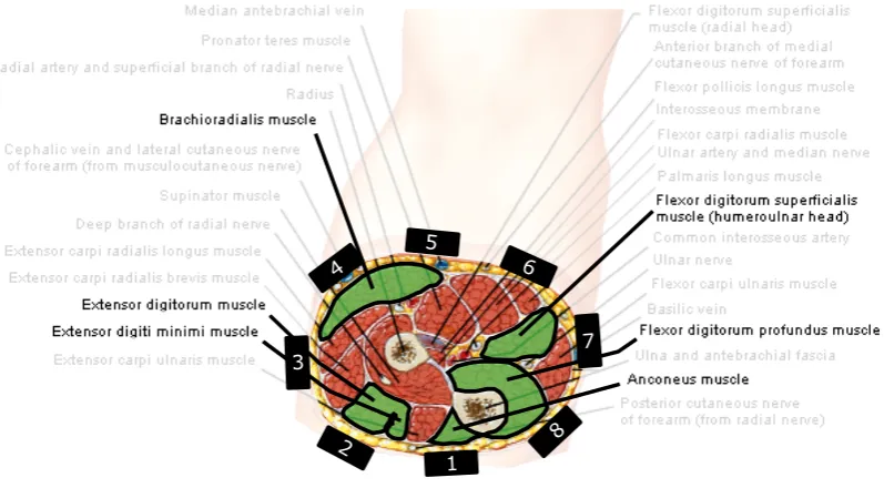
3.9 Schematic cross-sectional view of the human forearm, just below the elbow . . . 22
4.1 Schematic cross-sectional view of the human forearm, just below the elbow in-cluding possible placement of Myo electrodes . . . 27
4.2 Test results of second-order Butterworth low-pass filtered activation level signals versus the original signal received from the Myo Armband . . . 29
4.3 Outline of the omega.7 master controller and the KUKA slave controller . . . 30
4.4 Simple schematic representation of the designed haptic teleoperation system . . 31
4.5 Energy tank levels in time for switching virtual stiffness levels at time instantk without using energy compensation for impedance modulation . . . 36
4.6 Energy levels of two impedance controllers with different stiffness levels for a constant positional error resulting in different controller efforts . . . 37
4.7 Expected energy tank levels in time for switching virtual stiffness levels at time instantkwhile using the designed compensation algorithm . . . 37
4.8 Energy levels and difference in clipped energy for two impedance controllers with different stiffness levels for a constant positional error and constant force limitation 38
4.9 Screenshots of the KUKA LWR4+ model simulated in Gazebo in a wall mounted configuration . . . 40
5.1 Set-up configurations during the functional design validation experiments . . . . 47
5.2 Photo of the experiment set-up used during the experiments with test subjects . 48
5.3 Screenshot of the camera angle during the accuracy experiments . . . 51
5.4 Screenshot of the camera angle during the impact experiments . . . 52
6.1 Results of the functionality experiment in 3-DOF without any added communic-ation delay while using the simulated KUKA robot . . . 55
6.2 Results of the functionality experiment in 3-DOF with an added communication delay while using the simulated KUKA robot . . . 56
6.3 Results of the functionality experiment in 3-DOF while using the real KUKA robot 57
6.4 Results of the experiment that validates the energy compensation method for im-pedance modulation . . . 58
6.5 Commanded torques in every joint of the KUKA slave robot during the 3-DOF functionality experiment . . . 60
6.6 Example results of a calibration procedure for estimating the co-contraction levels of the user . . . 61
6.7 Results of the accuracy experiment versus the results of the impact experiment while no communication delay was added to the system . . . 63
6.8 Results of the accuracy experiment versus the results of the impact experiment while a communication delay was added to the system . . . 63
6.9 Overall mean absolute positioning errors for all tested impedance levels and com-munication delay settings . . . 65
6.10 Overall mean absolute peak controller forces for all tested impedance levels and communication delay settings . . . 67
E.1 Example result of the accuracy experiment for the low impedance setting without added communication delay . . . 78
E.2 Example result of the accuracy experiment for the high impedance setting without added communication delay . . . 78
E.3 Example result of the accuracy experiment for the variable impedance setting without added communication delay . . . 79
E.4 Example result of the accuracy experiment for the low impedance setting with the added communication delay . . . 80
E.5 xample result of the accuracy experiment for the high impedance setting with the added communication delay . . . 80
E.6 Example result of the accuracy experiment for the variable impedance setting with the added communication delay . . . 81
F.1 Example results of the impact experiment for the low impedance setting without the added communication delay . . . 82
F.2 Example results of the impact experiment for the high impedance setting without the added communication delay . . . 82
List of Figures ix
F.4 Example results of the impact experiment for the low impedance setting with the added communication delay . . . 84
F.5 Example results of the impact experiment for the high impedance setting with the added communication delay . . . 84
List of Tables
2.1 Overview of relevant specifications of the Force Dimension omega.7 haptic device 6
2.2 Overview of relevant specifications of the KUKA LWR 4+ robotic arm . . . 7
3.1 Muscles found in the human forearm related to flexion and extension of the fore-arm and fingers . . . 22
3.2 Relative advantages and disadvantages of relatively low and high impedance set-tings of a haptic teleoperation controller . . . 24
4.1 Relevant functions of the forearm and fingers with corresponding muscles and Myo electrode numbers . . . 28
4.2 Recommended parameter settings . . . 42
5.1 Overview of all parameters that were recorded during the experiments . . . 53
6.1 Computed static friction torques in the KUKA joints for clockwise and counter-clockwise rotations . . . 59
6.2 Maximum values of the absolute joint torques that were commanded during the 3-DOF functionality experiment for every direction of end effector motion . . . . 60
6.3 Overall mean values and standard deviations of the absolute positioning errors recorded during the accuracy experiments . . . 62
6.4 Overall mean values and standard deviations of the absolute peak controller forces recorded during the impact experiments . . . 62
6.5 Overall mean co-contraction levels during the accuracy experiments for periods of pausing, moving and these periods combined . . . 64
6.6 Percentage of change in overall mean absolute positioning error and the corres-pondingp-values when comparing the low impedance setting to the high and variable impedance settings . . . 65
6.7 Percentage of change in overall mean absolute positioning error and the corres-pondingp-values which resulted from the addition of the communication delay 65
6.8 Overall mean co-contraction levels during the impact experiments . . . 66
6.9 Percentage of change in overall mean absolute peak controller forces and the cor-respondingp-values when comparing the high impedance setting to the low and variable impedance settings . . . 67
6.10 Percentage of change in overall mean absolute peak controller forces and the cor-respondingp-values which resulted from the addition of the communication delay 67
A.1 Computed static friction torques in the KUKA joints for clockwise and counter-clockwise rotations . . . 75
B.1 Maximum extensor and flexor muscle activation levels established during the cal-ibration procedures . . . 75
List of Tables xi
C.2 Overview of the results of the accuracy experiments with the added communica-tion delay . . . 76
D.1 Overview of the results of the impact experiments without the added communic-ation delay . . . 77
Abbreviations and symbols
Abbreviations
Abbreviation Definition
DOF Degree Of Freedom
EMG Electromyography
ETP Energy Transfer Protocol
FRI Fast Research Interface
ROS Robot Operating System
PC Passivity Controller or Personal Computer PD Proportional-Derivative (controller) PF Position-Force (architecture)
PO Passivity Observer
PP Position-Position (architecture) SETP Simple Energy Transfer Protocol
TLC Tank Level Controller
Symbols - Latin
Symbol Unit Definition (fori=m(master) ors(slave))
dj [−] Joint specific damping ratio setting in the KUKA FRI
Dh [N·m·s/rad] Damping characteristic of the human arm
Dv [N·m·s/rad] Virtual joint damping
Dv,max [N·m·s/rad] Maximum virtual joint damping
Dv,mi n [N·m·s/rad] Minimum virtual joint damping
Fc,i [N] Clipped impedance control actions for devicei
Fcl i p [N] General constant controller action limitation
Fe [N] Forces applied by the environment
Ff r [N] Measured static friction forces
Fh [N] Forces applied by the human operator
Fi [N] Forces applied to devicei
Fi,max [N] Impedance control action upper bound for devicei
FK,i [N] Impedance control actions for devicei
˜
FK,i [N] Delayed impedance control actions for devicei
FP D [N] PD control actions
FT LC [N] Forces commanded by the TLC
Hab [−] Homogeneous transformation matrix from frameato frameb Hcl i p [J] Clipped energy as a result of saturation of control actions ∆Hcl i p [J] Energy change due to control action clipping
HD [J] Desired minimum energy tank level
∆He,i [J] Energy exchanged with the environment by devicei ∆H˜e,i [J] Estimated future energy exchange with the environment Hi [J] Energy tank level of devicei
˜
Hi [J] Estimated future energy tank level of devicei
Hi,d es [J] Energy tank level desired by transparency layer of devicei ∆HKv [J] Energy change due to impedance modulation
H+,i [J] Incoming energy flow for devicei
H−,i [J] Outgoing energy flow for devicei
J(q) [−] Jacobian matrix
k [−] Sample instant
xiii
Symbols - Latin (continued)
Symbol Unit Definition (fori=m(master) ors(slave)) Kd i s [N/m] Virtual stiffness of disabled DOFs
Kh [N/m] Stiffness characteristic of the human arm
Kr ot [Nm/rad] Virtual stiffness of rotational DOFs
Kv [N/m] Virtual stiffness level
Kv,max [N/m] Maximum virtual stiffness level
Kv,mi n [N/m] Minimum virtual stiffness level
oba [m] Translation of the origin of frameawith respect to frameb q [rad] Collection of robot joint angles
˙
q [rad/s] Collection of robot joint velocities
qmax [deg] Collection of maximum KUKA joint angles
˙
qmax [deg/s] Collection of maximum KUKA joint velocities
qs [rad] Collection of slave robot joint angles
˙
qs [rad/s] Collection of slave robot joint velocities
r [cm] Radius of force application measured from joint centre Rba [−] Rotation matrix from frameato frameb
Tac,b [m/s, rad/s] Twist of frameawith respect to framebexpressed in framec
ˆ
Tac,b [−] Unit twist ofawith respect to framebexpressed in framec ∆Ts [sec] Length of a sample period
vca,b [m/s] Translational velocity ofawith respect tobexpressed inc
Wa,b [N, Nm] Wrench applied to frameaexpressed in frameb Xc [m] Positional error at which control actions get clipped
Xe [m] Positional error of an impedance controller
˙
Xe [m/s] Velocity of the environment
˙
Xh [m/s] Velocity of (the arm of ) the human operator
Xi [m] Position of devicei
˜
Xi [m] Estimated position of devicei
˙
Xi [m/s] Velocity of devicei
Symbols - Greek
Symbol Unit Definition
α [−] Unitless muscle activation level ˆ
α [−] Normalised muscle activation level
αmax [−] Defined maximum muscle activation level
αmi n [−] Defined minimum muscle activation level
αf l ex [−] Flexor muscle activation level
αext [−] Extensor minimum muscle activation level
β [−] Transferred fraction of the energy tank level
γ [N·s/m·J] Damping parameter of the TLC in the stability layer η [−] Estimated co-contraction level
˜
η [−] Delayed estimated co-contraction level
τC md [Nm] KUKA torques commanded by the FRI
τD,s [Nm] Joint damping torques in the slave device
τF R I [Nm] Superposed torque command in the FRI
τmax [Nm] Maximum torque application in the KUKA joints
τs [Nm] Torques applied to the slave device
ωc,b
a [rad/s] Angular velocity ofawith respect tobexpressed inc ωc,l p [Hz] Corner frequency of a low-pass filter
1
1 Introduction
1.1 Context
The well-developed sensory and motor skills that humans possess allow them to effectively interact with a variety of environments. While they perceive their environment through the human senses like sight and touch, they are able to modulate their force application and the compliance of their limbs to dexterously interact with the environment. By modulating these dynamic properties, humans can create the desired manipulation behaviour corresponding to the tasks they are conducting. This task-dependent behaviour allows for a wide range of ma-nipulation tactics, like increasing limb compliance in order to carefully handle delicate objects or decreasing limb compliance to reject disturbing forces (Ajoudani et al., 2012; Brygo et al., 2015; Hill and Niemeyer, 2009; Shin et al., 2015; Walker et al., 2010).
However, humans are not always able to perform tasks safely or efficiently in some environ-ments like space, underwater or when toxic or nuclear materials are involved (Hashtrudi-Zaad and Salcudean, 2001; Hokayem and Spong, 2006; Niemeyer and Slotine, 1991).
Robotic systems on the other hand can be designed such that they can work in these human unfriendly environments, but generally lack the necessary dexterous manipulation skills. In-troducing advanced teleoperated robots could bridge the gap between the human dexterous manipulation skills and a robotic system that is designed to work in these environments. Tele-operated robots are remotely controlled by human operators to conduct tasks over a distance while feedback is presented to the operator in many possible forms like vision, audio, forces and vibrations. The research described in this thesis focusses on the haptic control of a robotic arm during which force feedback is provided to the operator. This forms a human-machine interaction which is aimed at projecting human manipulation skills to a remote environment (Chen et al., 2016; Walker et al., 2010).
The design of teleoperated robotic systems involves challenges in creating the feeling of tele-presence for the operator and ensuring stable and safe control of the robotic devices (Hogan, 1989; Hokayem and Spong, 2006). These challenges are faced in the joint innovation centre i-Botics, a collaboration between TNO and the University of Twente. A teleoperation platform is currently being developed within i-Botics, during which research is focussed on establishing effective, intuitive and safe teleoperation control.
1.2 Problem statement
One of the main challenges in the design of teleoperation systems that provide force feedback to the operator is dealing with time delays that occur when communicating with the teleoper-ated robot over a distance. These delays can especially be problematic in environments charac-terised by time-varying dynamics, since the human reaction to these changing dynamics will be delayed by the round-trip time of the communication channel (Hashtrudi-Zaad and Sal-cudean, 2001; Kim et al., 2005; Lawrence, 1993).
As a consequence, the safety levels of the teleoperation system and its environment can be negatively affected as this delayed reaction can lead to increased interaction forces between the robot and the remote environment (Ajoudani et al., 2012; Brygo et al., 2015; Walker et al., 2010).
of the human limbs such that the negative effects on the execution of telemanipulation tasks can be decreased. On top of that, it might be possible to create a more intuitive experience for the operator. Therefore, the main problem that will be studied in the proposed research is stated as the following:
"Can the dexterous compliant dynamic properties of the human limbs be captured and pro-jected to a haptic controlled teleoperation system and will this allow for more effective and intuitive execution of telemanipulation tasks?"
In order to capture the dynamic characteristics of the human limbs, this research will investig-ate the potential of using electromyography (EMG). With EMG, myoelectric signals are meas-ured that are sent to the muscles through the human central nervous system in order to activate them. These measured voltage levels can give an indication of the activation levels of muscles, from which an estimation of the dynamic properties can be determined. This estimation can be used at the remote site to respond to sudden changes in environment dynamics in a way that is similar to the human behaviour, without having to rely on information of the actual human reaction that is subjected to round-trip communication delays.
1.3 Related work
Several attempts in solving this problem were found in literature. Focus is placed on teleop-erated robots (slave devices) that are controlled by human operators through a haptic device (master device) which presents information on the interaction forces at the remote site through force feedback. Chen et al. (2016) conclude on positive results for the use of EMG, claiming that they were able to control a teleoperated robot more intuitively while increasing the track-ing performance as well. The actual effect on safety aspects like interaction forces were not studied in this research. Further indications that EMG can be used to identify human limb dy-namics are presented by Ajoudani et al. (2012). Although this research presents the use of EMG as an alternative to force feedback in teleoperation systems, it does show the extent to which EMG can be used in estimating the human limb characteristics. The research shows an iden-tification method for mass, stiffness and damping properties of the human arm in 3D, using EMG data from six relevant muscles.
Besides the use of EMG, other methods for estimating human dynamic characteristics have been applied in combination with force feedback in teleoperated robots. Research presented by Walker et al. (2010) shows the use of a gripper on the master device that is able to measure the grip pressure of the user and relates this data to the desired behaviour of the teleoperated robot. A tighter grip should then result in less compliant behaviour of the robot. This research shows clear benefits of using the variable compliant control on the robotic teleoperation sys-tem, mainly in reducing interaction forces in several situations.
Chapter 1. Introduction 3
1.4 Research goal
From the information on the context and the stated problem the following is stated as the main goal of this research:
"Create a teleoperation system that presents force feedback to the operator in which EMG data from the operator’s muscles is implemented in the control architecture to increase the intuitiveness and effectiveness of the execution of telemanipulation tasks while the system is subjected to time delays in its communication channel."
A teleoperation system will be created from available hardware in an attempt to reach this goal. Figure 1.1 shows the devices that will be used in the design of this set-up. The master device that registers the operator’s motions and applies force feedback is the omega.7 haptic device by Force Dimension, EMG data will be collected through a Myo Gesture Control Armband by Thalmic Labs and teleoperated slave robot will be a KUKA LWR4+ robotic arm. A computer simulated model of this KUKA robotic arm will be used as well in this research.
(a) (b) (c)
Figure 1.1: Pictures of the used hardware components: (a) Force Dimension omega.7 (master
device), (b) Myo Gesture Control Armband (EMG data collector) and (c) KUKA LWR4+ (teleop-erated robotic arm). Image credits: Force Dimension website (retrieved June 14th2017), Myo website (retrieved June 21th2017) and KUKA Roboter GmbH (2012).
1.5 Overview
5
2 Background
Information in this chapter purely functions as background information on the subjects that are addressed in this research. Readers familiar with one or more of these subjects can skip the corresponding sections. It includes some general information on teleoperation control, robotic manipulator control and specifications of the used hardware and software.
2.1 Teleoperation control
In order to create an effective teleoperation system, the teleoperated robot can be designed such that its sensory and motor systems resemble those of the human operator. By connecting the sensory and motor information of both the robot and the operator, an intuitive experience can be created for the operator. Terms generally found in haptic control, including telepres-ence, haptic feedback, transparency and stability, will be introduced in this section.
2.1.1 Telepresence
Telepresence describes the extent to which the operator will feel like he or she is conducting a task directly at the remote site (Chen et al., 2016; Lawrence, 1993). Increasing the amount of telepresence can for instance be accomplished through video and audio feeds and haptic feedback. The greater the feeling of telepresence for the operator is, the better he or she will be able to perform tasks in an intuitive way.
2.1.2 Haptic feedback
Over the past decades, the connection between the haptic senses of operators and the tele-operated robots has been studied in order to increase the level of telepresence. The human haptic senses create a tangible perception of the environment by gathering information on as-pects like motion, forces, shape, compliance, temperature, texture and vibration. The research that is presented here focusses on haptic feedback in the form of force feedback, which will be applied by a haptic interface (joystick) that can be used to register the operator’s motions to control the robot while also being able to apply forces to the operator. This way, information on the dynamic interactions that occur at the remote site can be reflected to the operator. Al-though haptic feedback creates a great step toward a more intuitive experience for operators, it involves challenges in creating the right feeling of telepresence while guaranteeing stable con-trol of all devices.
2.1.3 Transparency
Closely related to the level of telepresence is the level of transparency. This property is defined as the level in which the teleoperation system is able to accurately control the teleoperated ro-bot and reflect the interaction forces (Hashtrudi-Zaad and Salcudean, 2001; Kim et al., 2005; Lawrence, 1993). This forms the part of the feeling of telepresence related to the robotic devices. A high level of transparency is generally aimed for in the design of teleoperation ar-chitectures to increase the effectiveness and intuitiveness of the remote execution of tasks. However, increasing the levels of transparency often increases the risk of instability.
2.1.4 Stability
be guaranteed (Colgate and Schenkel, 1997; Hannaford and Ryu, 2002). A passive component is defined as a component that does not generate energy; the energy input can only be stored or dissipated. Consequently, energy supplied by this component can never exceed the energy stored in the system (Colgate and Schenkel, 1997; Niemeyer and Slotine, 1991). Furthermore, interconnecting passive components results in a system that is stable by definition (Colgate and Schenkel, 1997; Niemeyer and Slotine, 1991; Hogan, 1989).
2.2 Available hardware and software
The hardware components and software packages that are used during this research are dis-cussed in this section. Furthermore, some additional information is provided on the Cartesian and joint space control of a multi-DOF robot like the KUKA arm.
2.2.1 Hardware
Force Dimension omega.7
The Force Dimension omega.7 is a haptic device with 7 degrees of freedom (DOFs). The Cartesian coordinate frame is defined such that the large disc visible in Figure 1.1a is located in the (y,z)-plane with thex-axis perpendicular to the disc. Table 2.1 gives an overview of the rel-evant specifications of the omega.7. This haptic device allows for encoding translations along and rotations around the three axes, plus encoding the translation of the gripper. Furthermore, force feedback can be implemented along all translation axes, including the gripper. The most obvious limitation is that no torque feedback is possible around the axes of rotation.
DOFs Workspace Force application
Translation x-axis: 110 [mm] 12 [N] (y,z)-plane: 160 [mm]
Rotation
qx: 240 [deg]
N/A qy: 140 [deg]
qz: 180 [deg]
Grasping Stroke: 25 [mm] 8 [N]
Table 2.1: Overview of relevant specifications of the Force Dimension omega.7 haptic device. Source: brochure on Force Dimension website (retrieved June 14th2017)
Myo Gesture Control Armband
The Myo Gesture Control Armband is a light wearable developed by Thalmic Labs. It can be worn around the forearm, where it uses eight sets of electrodes to receive EMG data from su-perficial muscles. A software development kit is available which allows for reading levels of muscle activation from the Myo Armband through a Bluetooth connection. It can provide an array of eight integer values corresponding to each electrode at 50 [Hz]. These integers are unitless measures for the muscle activation levels, based on the EMG readings.
KUKA LWR4+
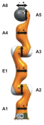
The KUKA LWR4+ is a 7-DOF robotic arm with a working envelope of 1.84 [m3] and a weight of 16 [kg]. Figure 2.1 presents an overview of the location, orientation and names of the seven joints and Table 2.2 gives an overview of range (qmax), maximum speed ( ˙qmax) and maximum
Chapter 2. Background 7
Figure 2.1:Overview of joint configurations and names in the KUKA LWR 4+ robotic arm. Image credit: (KUKA Roboter GmbH, 2012)
Joint name qmax[deg] q˙max[deg/s] τmax[Nm]
A1 ±170 110 176
A2 ±120 110 176
E1 ±170 128 100
A3 ±120 128 100
A4 ±170 204 100
A5 ±120 184 38
[image:23.595.266.339.81.286.2]A6 ±170 184 38
Table 2.2:Overview of relevant specifications of the KUKA LWR 4+ robotic arm. Source: KUKA Roboter GmbH (2012)
The KUKA arm has its own controller named the ‘KRC’, which can be accessed at low-level and at high control rates through the Fast Research Interface (FRI) (Schreiber et al., 2010). This allows for instance for the implementation of the following joint specific impedance control law:
τC md=kj(qF R I−qmsr)+D(dj)+τF R I+fd ynami c s(q, ˙q, ¨q) (2.1)
Here,τC md is control actions that is commanded to the joint actuators, kj includes the joint
specific stiffness values representing a virtual torsional spring betweenqF R I, the desired
an-gular positions of the joints andqmsr, the current angular positions of the joints.
Further-more, normalised damping parameters included in the damping ratiodjcan be added to the
joints, reaching from no damping (dj =0) to critical damping (dj =1). Finally, additional
torques can be superposed inτF R I. The FRI will add a compensation of certain dynamics, fd ynami c s(q, ˙q, ¨q). It is known that this contains the options of gravity compensation, other
forms of dynamics compensation are unknown. The variables ˙q and ¨q might suggest a com-pensation of (parts of the) friction and inertia of the robot.
link lengths and joint configurations presented in Figure 2.1 are known, the configuration of the distal end (the end effector) of the robot can be expressed in the frame of its proximal end (its base). Going from joint to joint along the robot, every link will have its own frame which is rotated and translated with respect to the previous one. Such a combined rotation and transla-tion can for instance be represented in a homogeneous matrix:
Hab= ·
Rab oba
0 1
¸
(2.2)
This represents the transformation from framea to frameb, containing the rotation matrixR fromatoband a translationoof the origin fromatob. When multiplied by a vector corres-ponding to a point in frameaexpressed as [xa,ya,za, 1]T, the expression of this point in frame
b results. Once every individual homogeneous matrix along the robot’s length is known, the chain rule can be applied to find the configuration of the end effector frame (n) expressed in the base frame of the robot (0):
Hn0=H10H21...Hnn−1 (2.3)
The homogeneous matrixHn0then gives the information on the position and orientation of the robot’s end effector with respect to its base.
Another mathematical approach that is often used to relate the joint space and the Cartesian space of the robot is the use of a geometric Jacobian. This matrix, often expressed as J(q), relates the joint velocities of the robot to the velocity of its end effector. In screw theory, these Cartesian velocities are expressed as twists like the following:
Tac,b= "
ωc,b a
vac,b #
(2.4)
Here,Tac,bis the twist of frameawith respect to frameb, expressed in framec. It consists of an
angular velocityωand a linear velocityv. With a Jacobian matrix, the twist of the end effector with respect to the robots base, expressed in the frame of this base, can be found when the angular velocities of the joints are known:
Tn0,0=J(q) ˙q (2.5)
Twists can also be used to create the contents of the Jacobian matrix. The Jacobian is a collec-tion of unit twists, expressed as ˆT. In a unit twist, the length of the vectorωis equal to one or if
ωis zero, the length of the vectorvshould be equal to one. All unit twist express the motion of a link with respect to the previous link in the base frame of the robot:
J(q)=£Tˆ10,0Tˆ20,1... ˆTn0,n−1 ¤
(2.6)
This Jacobian can also be used to compute joint torque commands for the robot when a certain combination of end effector force and torque is desired. This combination is called a wrench in screw theory. In the equation below, the transposed Jacobian matrix is used to find joint torques that correspond to a wrench (W0,n) applied to the robot’s end effector while it is expressed in the robot’s base frame:
Chapter 2. Background 9
2.2.2 Software
Robot Operating System (ROS)
In building the proposed teleoperation system, several hardware components will need to be connected to each other through a digital controller. In order to let the different components communicate with this controller, the Robot Operating System (ROS) will be used. ROS offers a framework for writing robotic control software by supplying sets of tools, libraries and con-ventions which should simplify this communication task. It is aimed at collaborative software development which makes it very useful in connecting the different pieces of hardware through software (ROS website, retrieved July 10th2017).
All components of the communication structure, like code that controls the hardware or code that includes the general control algorithms, will be written (or already exists) in the from of ROS nodes. These nodes can communicate with each other through topics. Nodes can publish data on these topics and/or subscribe to receive data from the topic. This data is transferred in the form of messages of basic types which allows for independent communication between nodes. Furthermore, nodes can request services from other nodes. Code for the ROS nodes will either be reused from other projects or created for the requirements of the proposed research.
Gazebo
11
3 Analysis
This chapter presents an overview of the analyses conducted during this research to come to a design strategy. It discusses a general teleoperation system outline, after which transparency and stability properties, problems and solutions are discussed. Next, useful literature is dis-cussed in more detail regarding the stated problem and the possibilities of using EMG to solve this problem are discussed. Finally, hypotheses are stated based on the presented analyses.
3.1 Teleoperation system outline
Generally, a haptic controlled teleoperation system that reflects forces to the operator consists of the following components: a human operator that holds a haptic interface (master device), a robotic manipulator (slave device) that interacts with the remote environment and a connec-tion between the two devices that consists of controllers and a communicaconnec-tion channel. These components are schematically depicted in Figure 3.1. The components all interact with each other, whether through software or physically. Shaping the interactions is what will be most im-portant when designing the teleoperation system, since the hardware components are known and the system should work for any variety of human operators and environments. As indic-ated in the figure, focus is therefore placed on designing the controllers and a communication channel, including their interactions with the hardware components.
Figure 3.1:Simple schematic overview that illustrates the basic interactions between compon-ents found in a 1-DOF haptic teleoperation system.
An energy-based analysis approach is often adopted in designing haptic controlled architec-tures since stability is often guaranteed through the passivity theorem (Colgate and Schenkel, 1997; Niemeyer and Slotine, 1991; Hannaford and Ryu, 2002; Hogan, 1989). When designing the hardware controllers and the communication channel, the energetic interactions between the components of the system are shaped and passivity can be analysed while striving for the highest level of transparency possible.
3.2 Transparency
The transparency level that results from the energetic interactions between the master and slave devices depends on hardware and design choices. Therefore, the used hardware will be analysed to further specify the inputs and outputs of the controllers. Then, a suitable interac-tion control strategy between the hardware components is determined. Finally, the methods for transparency control that fit this approach are presented and discussed.
3.2.1 Analysis of the hardware
by dynamic properties like low inertia, low friction and high backdrivability. Admittance type devices preferably receive a position or velocity command as a response to measured forces or torques and are characterised by relatively high inertia and friction properties, for instance caused by heavy gearing.
Based on the description of the characteristics, the omega.7 haptic device can clearly be qual-ified as being of the impedance type. It has low inertia and friction properties and it is able to execute force commands while data on positions and velocities can be read from the system. The KUKA arm on the other hand is harder to qualify. It possesses more inertia and friction than the omega.7, but when considering its size and degrees of freedom it is a relatively light-weight robotic arm in its class. As discussed in Chapter 2, the KUKA arm can be controlled trough its FRI which will command actuator torques. This makes this robotic arm an imped-ance controlled device as well. However, its inertial and frictional properties might harm the transparency level of the system, especially during free-space motions (Ott et al., 2010).
When viewing both devices as preferably impedance controlled, a controller should be de-signed that creates the interaction between both the devices which suits their causality.
3.2.2 Interaction control
In order to create both an effective and safe robotic teleoperation system, both motion tracking and interaction force control are of importance (Brygo et al., 2015; Hill and Niemeyer, 2009; Walker et al., 2010). Generally speaking, admittance type devices provide high levels of motion tracking accuracy but suffer from problems like instability when force commanding is desired, for instance when in contact with rigid objects. Impedance type devices can more easily be force controlled in a stable manner, but dynamic properties of the devices can harm the motion tracking capabilities (Ott et al., 2010).
Both devices used in this research will be impedance controlled, creating a fixed causality of the controller. The inputs will be based on the position and/or velocity information of the devices, while the outputs will be forces or torques. An impedance connection between two devices can be seen as a virtual spring, in which the level of transparency of the interaction is limited by the stiffness of this connection. Furthermore, virtual damping is generally added to reduce oscillatory behaviour of the virtual connection. During this research, this virtual damping will be added in every single joint of the KUKA arm. This way, damping is not subjected to the delays in communication between the master and slave devices. Furthermore, adding damping in every joint is preferred over Cartesian damping of the end effector because this will damp out kinetic energy in the robot’s null space as well. Since the KUKA is a 7-DOF robot, it will be able to move its links without moving its end effector, which is generally referred to as motion in its null space. Figure 3.2 presents a simple schematic interpretation of such a virtual connection in a haptic teleoperation set-up while only representing 1-DOF for simplification.
Dh
Kh
Kv
Xm Xs
Human arm & Master device
Slave device
Dv
qs
Chapter 3. Analysis 13
Here, the arm of the human operator and the master device are seen as one, while possessing the stiffness and damping characteristics of the human arm (KhandDhrespectively) and while
the Cartesian end effector position is referred to asXm. At this end effector position, one end
of the virtual spring with stiffnessKvis attached while the other end is connected to the slave’s
end effector positionXs. Furthermore, virtual dampingDv is present in its joint which has a
rotational displacement ofqs. The stiffness and damping properties present in the hardware
are assumed to be negligible here. When the communication channel is disregarded, the im-plementation of the virtual stiffness will apply Cartesian forcesFK,mandFK,sto the master and
slave devices respectively:
FK,m=Kv·(Xs−Xm)
FK,s= −Kv·(Xs−Xm)
(3.1)
Damping is added in the joints of the slave robot by commanding torquesτD,s to the joints,
depending on the angular velocity of the joints ( ˙qs):
τD,s= −Dv·q˙s (3.2)
When aiming for the highest transparency level possible,Kvis generally maximised to
repres-ent the stiffest connection possible. This allows for the most accurate reflection of motion and forces. However, high values forKvcan also be the cause of the reported high interaction forces
when the system is subjected to communication delays. When no delays are present, the re-mote environment will experience the slave device as having compliant properties similar to the human arm ifKv ÀKh. When the human reaction is delayed through the
communica-tion channel, the behaviour that will be felt will be determined by the stiff conneccommunica-tion made by Kv, leading to the high interaction forces. LoweringKvpermanently will however result in poor
transparency, since the operator will feel a weak spring in between everything he or she touches and the motion tracking will be less accurate as well. MakingKv(and correspondingDv)
vari-able is a solution that was found in literature before (Chen et al., 2016; Hill and Niemeyer, 2009; Walker et al., 2010). This method is often referred to as impedance modulation, or the resulting variable impedance control. However, these attempts have been quite exploratory and do not focus on the design of a complete and stable system that includes time delayed communic-ation. The research that is presented here will further investigate an impedance modulation strategy in haptic control by using EMG data from the operator’s muscle activation.
3.2.3 Transparency control
Realising an impedance controlled teleoperation system can be accomplished with multiple control architectures. Many strategies have been discussed in literature, Hokayem and Spong (2006) present a basic overview of the most commonly used strategies. Although in theory full transparency can sometimes be achieved when no communication delay is present in the system (Hashtrudi-Zaad and Salcudean, 2001; Kim et al., 2005), it requires many information channels (like the four-channel architecture in which position and force information is ex-changed for both master and slave device) and it requires accurate knowledge of the dynamics of the devices and its environments. Since the latter is almost never possible, extensive adapt-ive control schemes can be used to create accurate estimations of these dynamics. Because of the need of many sensors and complex control architectures, these methods are not further investigated in this research. It is expected that the functioning of the proposed variable im-pedance control strategy can be indicated with more simple, two-channel control approaches.
In this scheme, the slave controller block contains the impedance controller that is used as the interaction controller on the slave side. This controller relies on an estimation of the master’s end effector position ( ˜Xm). This is called an estimation because information onXmcan be
sub-jected to communication delays. Because the slave device is located and controlled at a remote site, it is important that a local impedance controller is running here. In case of communication loss, the behaviour of the slave device will be stabilised by its local impedance controller.
Figure 3.3:Simple schematic overview that illustrates the basic energetic interactions and com-municated variables in an impedance controlled haptic teleoperation system.
On the master side, several types of master controllers can be implemented which rely on dif-ferent types of information received through the communication channel, hence the question marks in the figure. Two approaches found in literature suit the scheme of Figure 3.3, generally referred to as the position-position (PP) architecture and the position-force (PF) architecture (Hashtrudi-Zaad and Salcudean, 2001; Lawrence, 1993). These names indicate the two para-meters that are sent through the communication channel: both rely on the master controller sending position information to the slave controller, while the slave controller can either send position information (PP) or force information (PF). The difference between these approaches will be analysed here.
Position-position (PP) architecture
Figure 3.4 shows a simplified sketch of a teleoperation system subjected to time delays in its communication channel while using the PP architecture. It can be interpreted as having two impedance controllers, one on the master and one of the slave side. This configuration has a few benefits. As long as ˜Xs and ˜Xm are stable and the impedance controllers show stable
Chapter 3. Analysis 15
Dh
Kh
Kv
Xm X˜ Xs
m
Kv
˜ Xs
Dv
Human arm & Master device
Slave device
Figure 3.4:Simplified schematic representation of a 1-DOF haptic teleoperation system using an impedance controller and a position-position (PP) communication architecture.
Position-Force (PF) architecture
Figure 3.4 shows the simplified sketch while the PF architecture is applied. The energy trans-ferred over the communication channel is clear, since it is the energy that is stored in and con-sumed from the same impedance controller. This allows for relatively easy energy monitoring and energy shaping to create a stable system. Furthermore, where the PP architecture tends to receive an overly conservative amount of energy from the operator, the PF architecture gener-ally receives too little energy. In order to provide a stable interaction, this energy should then be compensated for by an additional control facility. These options will be discussed in the next section. By compensating for the correct amount of energy, PF architecture creates the less conservative option. For these reasons, this architecture will be used in the design of the teleoperation system during this research.
Dh
Kh
Xm ˜ Xs
Xm
Kv
Dv
Human arm & Master device
Slave device
FK,m= −F˜K,s
3.3 Stability
In order for the teleoperation system to function both safely and effectively, stability of the sys-tem should be guaranteed. Unstable behaviour of the syssys-tem contains undesired divergent or oscillatory motions of the master and/or slave device (Hannaford and Ryu, 2002). Guarantee-ing stability of the system can be achieved by guaranteeGuarantee-ing passivity. Experiments conducted by Hogan (1989) indicated that the impedance of a human arm can be assumed passive. Since a system of interconnected passive components is a passive system by definition, a passive teleoperation control system and communication channel which are used in a passive envir-onment and operated by a human can be assumed to be a passive system. The causes of loss of passivity will be analysed here after which possible solutions are discussed.
3.3.1 Loss of passivity
Loss of passivity can occur in delayed systems: in haptic control, this is mainly seen as delays in the communication channel or as the effect of digital sampling in the control architecture (Col-gate and Schenkel, 1997). Seemingly passive control architectures, like the impedance control-ler proposed in this research (see Equation 3.1), can show active behaviour (i.e. production of energy) as a result.
Weir and Colgate (2008) describe that controlling continuous-time systems in discrete-time can cause loss of passivity. They describe the occurrence of energy leaking which adds virtual energy to the controllers, resulting in active behaviour. When transforming from continuous-time to discrete-continuous-time in digital control, sampling of motion information (e.g. position or ve-locity) is used at sample instants spaced by the length of the sample period (∆Ts). The
res-ulting discrete control actions, in the form of torques or forces, are generally applied to the continuous-time system for the length of this sampling period using a zero-order hold. This means that during the length of a sampling interval, the control action is not adjusted to the continuously changing motion of the system. Figure 3.6 gives a graphical interpretation of the difference between this theoretical continuous behaviour and the discrete behaviour of a di-gital impedance controller, which can be viewed as a linear spring.
Time [s]→
F
or
ce
[N
]
→
0
∆Ts
Discrete-time force Continuous-time force
Figure 3.6:Force application of a linear spring when compressed and extended around its centre position (0) in continuous-time (dashed line) and discrete-time (solid line) with sample lengths ∆Ts.
Chapter 3. Analysis 17
decompression, too much energy is extracted. This creates the active behaviour found in these types of controllers: energy not only stored, but also added by the virtual stiffness. Further-more, it can be concluded that the general cause of this is time delay, which can be the result of communication delays as well as the result of sampling.
Increased loss of passivity is seen for increased stiffness values of these controllers (Ajoudani et al., 2012; Brygo et al., 2015). This can be understood from Figure 3.6 as well: for higher stiff-ness values, the slopes in the continuous-time force application will be steeper. This will create a larger mismatch between the desired continuous-time behaviour and the actual discrete-time active behaviour. This mismatch in energetic interaction is depicted in a schematic way in Figure 3.7. Here, the energy levels of two ideal springs with different stiffness levels are in-dicated by the solid lines, while the springs start at their relaxed states, containing zero energy. Then, the springs are sequentially compressed and decompressed after which they reach their relaxed states again. The discrete-time behaviour of a impedance controller that represents these springs is indicated by the dashed lines. With respect to the ideal spring, which is repres-ented by the solid line, too little energy is added during compression while too much energy is extracted during decompression. This mismatch is indicated by the energy level of the dashed lines, reaching below zero. Since reaching an energy state smaller than zero is not possible, it indicates that energy was generated in the virtual stiffness that caused this behaviour. As men-tioned, this mismatch will increase when the stiffness is increased, as is also indicated in Figure 3.7.
Time [s]→ Time [s]→
Kl ow Khi g h
0 0
Ideal behaviour Active behaviour
E ner gy [J ] → E ner gy [J ] →
Figure 3.7:Visual interpretation of the energy levels of two virtual springs with relatively low and high stiffness values (solid lines) and the active discrete-time behaviour found in impedance con-trollers (dashed line). The virtual springs begin at a relaxed state after which they are sequentially compressed and decompressed until the relaxed state is reached again.
3.3.2 Guaranteeing passivity
Since this active behaviour cannot always be prevented, the system has to be designed such that the produced energy is always dissipated in order to remain passive. However, being too conservative by dissipating too much energy will decrease the transparency of the system (Col-gate and Schenkel, 1997; Hannaford and Ryu, 2002; Lawrence, 1993). Here, solutions found in literature will be discussed to guarantee passivity of the system.
Scattering theory and wave variables
Successful attempts of creating passive, delayed communication are seen in the application of scattering theory and wave variables. Within the communication channel, both constant and variable time delays can occur or even loss of data. It was introduced by Niemeyer and Slotine (1991) and many extensions have been introduced for this application to work in all kinds of circumstances and while striving for the best transparency level possible (Hokayem and Spong, 2006). However, it does only concern the creation of a passive communication channel while sampling effects in discrete-time controllers are neglected. Furthermore, creating a system based on this method which can deal with different kinds of communication problems like variable delays and package loss requires complex extensions. Eventually, the method also has to provide stability while the stiffness of the virtual connection is changed through impedance modulation. Extending the current knowledge on scattering theory and wave variables to cope with impedance modulation effects will not be trivial, there are other methods available that use more simplistic energy-based approaches which allow for easier extension. For these reas-ons, this method is not investigated further. Other methods are able to give better and less complex insights into the energetic interactions of teleoperation systems and allow for more simple extensions.
Numerical integration of conjugate variables
Hannaford and Ryu (2002) describe the use of a "passivity observer" (PO) and a "passivity con-troller" (PC). The passivity observer monitors the energy flows in systems with high sampling rates by simple numerical integration of the multiplication of power conjugate variables, e.g. velocity and force. These are variables that, when multiplied, indicate the power of the system. Both the operator and the environment can add energy to the system by creating a motion of the devices in the opposite direction of the control forces. Imagine for instance a simple im-pedance controller, of which the stored energy can be increased by increasing a position error while the controller applies control actions in the opposite direction in an attempt to decrease the position error. In the opposite situation, when the devices move in the direction of the ap-plied control action, energy will be extracted from the system. Whenever the observer notices that more energy is extracted by the control actions than was added by the operator or envir-onment because of the discrete time sampling effects described earlier, the same amount of energy will be dissipated by the passivity controller (e.g. a virtual damper). This means energy is only dissipated to prevent actual active behaviour, resulting in a system that is not overly conservative. The method does require very high sampling rates for the information on the conjugate variables in order to reliably integrate.
Discrete time energy monitoring
Chapter 3. Analysis 19
the energy exchange can easily be estimated from available data, after a sample period has ended. The below equation gives an example of this principle in 1-DOF:
∆He(k)=F(k−1)·(x(k)−x(k−1)) (3.3)
Where∆He(k) represents the energy exchange that happened between sample instantsk−
1 and k, F(k−1) represents the (zero-order hold) force applied during this period and (x(k)−x(k−1)) is the resulting difference in position which was established during this period.
Using this method, Kim and Ryu (2010) estimate the active behaviour of their controller. Fur-thermore, they estimate the amount of dissipated energy in the system. Next, they limit their control actions such that the energy leakage will not exceed the amount of dissipated energy, creating a passive system. A disadvantage of this method is that an accurate estimation of the physical dissipation is required that can never exceed the real amount of dissipation in order to guarantee passivity. Underestimating the amount of physical dissipation will however result in decreased transparency levels found in overly conservative systems.
The energy monitoring technique of Equation 3.3 can also be used in a variable damping tech-nique similar to what was seen in the research of Hannaford and Ryu (2002). An approach described by Franken et al. (2011) referred to as the "passivity layer" can be used to stabilise controllers and communication channels. In this method, a clear distinction is made between a transparency layer, which calculates the desired control forces/torques to reach the desired level of transparency, and a passivity layer, that only saturates the control actions and is able to add virtual damping when needed to guarantee a passive system. It monitors energy flows in the same way as discussed for the energy bounding algorithm by Kim and Ryu (2010) but extends the method for separate master and slave systems, both having to deal with active be-haviour. In this approach, virtual energy tanks are located at both the master and slave side which are able to send energy packets to each other through the communication line. An al-gorithm will constantly try to balance the energy levels of both tanks. Energy can only be added to or extracted from these tanks by the operator at the master side or the environment at the slave side. Control actions at each side will be saturated depending on what the energy level of the corresponding tank allows. With knowledge of the system’s state and the length of time samples, it can be estimated what control action will be allowed during the sample period in order to not consume more energy that is available at the start of the sample period. This way, only the energy that is put in by the operator or the environment can be used in controlling the robotic devices which should guarantee stability. If more energy is consumed than what was stored in the energy tanks, energy will be extracted from the user into the energy tank at the master side, for instance through a virtual damper. However, since a control action is needed for the operator to add energy to the control system, a deadlock situation can occur when the tanks are completely drained which will not allow for any control action. This can be prevented by maintaining a minimum energy level in the tank at the master side, so energy is extracted from the user to restore this level. It does however mean that there is more energy available for the system to use during a sample period in which the energy extraction at the master side will not change so there is more room for active behaviour during a sample period. The min-imum energy level should be pre-set and will not be trivial since it related to some amount of allowed active behaviour. This decision will mainly be influenced by the sampling rate and energy consumption of the system.
3.4 Variable impedance control based on human motor behaviour
During the analysis of transparency strategies (Section 3.2) a variable impedance control strategy was proposed as a possible solution to the problem stated in this research. With vari-able impedance control, constant modulation of the spring and damper characteristics can be used to influence both motion tracking effectiveness and force/torque application, similar to human manipulation behaviour. Several attempts to relate the impedance levels of a haptic teleoperation controller to human motor behaviour were found in literature.
Research conducted by Chen et al. (2016) shows a number of similarities with the research that is presented here. Although the nature is quite exploratory, with a number of features added to a telemanipulation system all at once, some testing has been done using multiple test subjects while a Myo Armband was used. The control architecture however is briefly explained and design choices are not very clear, especially regarding stability.
Both Chen et al. (2016) and Walker et al. (2010) indicate promising, desirable effects on the transparency properties and the intuitiveness of the teleoperation systems they designed. Their approaches in creating transparency differ, with Walker et al. (2010) using one impedance con-troller to determine the forces applied to both the master and slave device, while Chen et al. (2016) changed the gains of a position controller found on the master device while an imped-ance algorithm determined the amount of force feedback that was presented to the user. When regarding passivity for instance, the approach of Walker et al. (2010) gives a framework in which energetic interactions are more clear and can be compared, balanced and adapted when ne-cessary. Furthermore, Walker et al. (2010) clearly indicate that, although a controller may be very compliant, the interaction forces resulting from an impact situation occur instantly and will be determined by the mechanical properties of the robot rather than its controller set-tings. This is something that should be kept in mind. Higher compliance might result in lower contact forces, but impacts happen at frequencies far beyond the bandwidth of a controller. To solve this, Walker et al. (2010) introduce a mechanical clutch which can be varied through impedance estimation as well. Regarding the hardware used during the current research, this unfortunately is not a possibility.


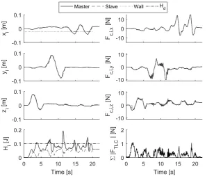
![Figure 6.2 shows the results of this experiment repeated with an added delay in the communic-ation channel of 10 [msec]](https://thumb-us.123doks.com/thumbv2/123dok_us/9710936.472136/72.595.130.450.213.466/figure-shows-results-experiment-repeated-added-communic-channel.webp)