An Inclusion-Exclusion Algorithm for Network Reliability
with Minimal Cutsets
Yan-Rui Sun, Wei-Yi Zhou
1
School of Sciences, Northeastern University, Shenyang, China
2
School of Electronic Information, Wuhan University, Wuhan, China Email: [email protected], [email protected]
Received August 10,2012; revised October 9, 2012; accepted October 23,2012
ABSTRACT
The inclusion-exclusion formula (IEF) is a fundamental tool for evaluating network reliability with known minimal paths or minimal cuts. However, the formula contains many pairs of terms which cancel. Using the notion of compara-ble node partitions some properties of canceling terms in IEF are given. With these properties and the thought of “dy-namic programming” method, a simple and efficient inclusion-exclusion algorithm for evaluating the source-to-terminal reliability of a network starting with cutsets is presented. The algorithm generates all the non-canceling terms in the unreliability expression. The computational complexity of the algorithm is O n
m3M
, where n and m are the numbers of nodes and minimal cuts of the given network respectively, M is the number of terms in the final symbolic unreliability expression that generated using the presented algorithm. Examples are shown to illustrate the effectiveness of the algorithm.Keywords: Inclusion-Exclusion Formula; Network Reliability; Minimal Cutset; Dynamic Programming
1. Introduction
The reliability of a network is an important parameter in design and operation of networks. There are many meth- ods to compute the reliability of networks [1,2]. Several algorithms exist in the literature for evaluating the reli- ability of a directed graph by inclusion-exclusion formula (IEF) based on either path (k-tree) enumeration or cutset enumeration [3-8]. In finding the k-terminal reliability by IEF there are two approaches, one based on enumerating all k-trees and the other based on enumerating all k-terminal cuts. If there are m minimal paths (or cuts) in a graph, there are possible intersection terms in IEF. However, the number of non-cancelling terms in IEF is considerably less.
2m1
Starting with the set of paths (or k-trees) of a directed graph, Satyanarayana and coworkers [5,6] developed methods of identifying non-cancelling terms in IEF. They showed that the non-canceling terms of the source- to-terminal reliability correspond one-to-one with the p-acyclic subgraphs of the given graph. An algorithm was given for generating all the p-acyclic subgraphs of a directed graph [5]. Buzacott [3] gave a corresponding result for the non-cancelling terms in IEF starting with the set of cuts of a graph. Since each term in the resulting formula is associated with a partition of the set of nodes of the graph, it was called the node partition formula.
Find all the node partitions of a graph is a very tedious work.
Using a lemma (the Lemma 3.4 of [3]) of incompara- ble node partitions of [3] and characteristics of canceling terms in IEF, by the thought of “dynamic programming” method a simple and efficient inclusion-exclusion algo- rithm is given in this paper for evaluating the source- to-terminal reliability of a graph based on minimal cuts. The algorithm generates only the non-canceling terms of the reliability expression of the graph.
2. Nomenclature, Notation and Assumption
A network is modeled as a directed graph G N E
,
(abbreviated to G) which consists of a set of nodes N and a set of edges (links) E. A node sN is the source of G and t N
s is the terminal of G.2.1. Nomenclature
Source to terminal (s – t) reliability: the probability that the source s is connected to the terminal node t by paths working edges.
s t cut: a subset of edges whose removal divides the node set of the network into two parts Ni and Ni such
that NiNi N, sNi and tNi, i.e. the edge set
Minimal st cut: st cut which no longer re- mains a st cut if its any edge is removed.
Candidate child set of Ni: an ordered set
Ni1,Ni2,,Nir
1,
i i
N N
consisting of all the node sets such that j
j 2,,r
,1 2 r
i i
N N Ni
2
.
Incomparable node sets: a pair of node sets and
such that and .
1
N
2
N N1N N2N1
2.2. Notation
i
N :subset of Nsuch that sNi
i
N : complement ofNi, and tNi
N Ni, i
: cut, i.e. the edge set from Ni to Nii
C : 1) cut
N Ni, i
1) event that all the edges of cut i fail :1) union of all the edges of cuts and
C
i j
C C Ci Cj
2) intersection of events Ci and C j i
U
(N
: union of i cuts )
i
: candidate child set of Ni
Pr : the probability of event
,G
Q s t : source-to-terminal (s – t) unreliability of G
2.3. Assumption
1) G has perfectly reliable nodes and s-independent 2-state (good and failed) edges, and the reliability of each edge has been given.
2) Let Ci
N Ni, i
and Cj
N Nj, j
be mincutsof G, then Cij
NiNj,NiNj
is also a min-
cut of G.
3. Preliminaries
Let be the set of mincuts of a given network G where corresponds one-to-one with the
C C1, 2,,CmCi
node set Ni, i.e. Ci
N Ni, i
m
(i1, 2,, ). The s – t unreliability of G, by IEF, can be expressed as
1 2 1 1 1 1 2 1 , Pr Pr PrPr 1 Pr
G
m
i i j
i m i j m
m
i j k m
i j k m
Q s t
C C C
C C C
C C C C C C
(1)the summations are over all mincuts and mincut combi- nations.
In formula (1), there exist possible terms. But it is possible that i j for some , . Indeed
the most vexing problem in reliability analysis using (1) is the appearance of large numbers of pairs of identical terms with opposite sign, which cancel. Find the charac-
teristic of canceling terms in (1) is the keystone of an efficient algorithm. Buzacott gave a simple and very useful lemma (Lemma 3.4 of Ref. [3]) to identify some canceling terms in (1).
2m1
U U i j, i j
Lemma 1. Given any two mincuts Ci
N Ni, i
and
,
j j j
C N N of G such that Ni and Nj are incom-
parable, all terms in IEF containing both Ci and Cj
cancel if Cij
NiNj,NiNj
is also a mincut [3].In formula (1), assume that N1 N2 Nm .
According to Lemma 1, (1) can be changed into:
1 2
1 2 1 2 1 2 1 1 1 1 1 , Pr Pr Pr Pr 1 Pr i j
i j k
k
i i ik
k
G m
i i j
i m N N
i j m
i j k
N N N
i j k m k
i i i
N N N
i i i m
Q s t C C C
C C C
C C C
C C C
(2)the summations are over all mincuts and mincut combi- nations that satisfy the given conditions.
The terms in (2) can correspond one-to-one the vertex of the m rooted trees with the following properties.
1) The root vertex of each rooted tree is the vertex i
corresponding to cut set , its weight is , sign is +1.
N
i
C N
i
2) Sons of each vertex i in every rooted tree are all
elements in
C
Ni , each son’s weight is the union of its father’s weight and the cut set corresponding to this son vertex, sign is its father’s sign times –1.
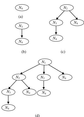
For example, let N1N2N3N4, Ci
N Ni, i
i1, 2, 3, 4
. Figure 1 are four rooted trees.In Figure 1(a), tree (N4) has a only vertex, the root
vertex N4. Its weight is C4, sign is 1. In Figure 1(c), tree
(N2)’s root vertex is N2, its weight is C2, sign is 1. N2 has
two sons: N3 and N4. The son vertex N3’s weight equals
to C2C3, signis –1; N4’s weight equals to C3C4, signis –1.
N3’s son is N4, here N4’s weight equals to C2C3C4, signis
1 1 1 .
The weight with its sign of each node in the rooted trees one-to-one corresponds with the term in the expres- sion of formula (2). So we discuss m rooted trees’ gener- ating. The rooted tree whose root is is denoted as tree
i
N
Ni .In fact, if we generate the rooted trees in non-increas- ing order of root’s modulus and generate the sons of each vertex in non-decreasing order of the son’s modulus, we can use the trees which have already been generated to generate the following trees. For example, Figure 1 are four rooted trees, where tree
N3 is a branch of tree
N2 , tree
N2 and tree
are the branches oftree
3
N
N1 . If tree
N3 is generated firstly, we can use(b) (c)
N2
N3
N4
N4
N3
N4
N4
(a)
(d)
N4
N1
N2
N4
N4
N3
N4
[image:3.595.84.257.82.322.2]N3
Figure 1. Rooted sub-trees. (a) Sub-tree(N4); (b) Sub-tree(N3);
(c) Sub-tree(N2); (d) Sub-tree(N1).
generate tree , we can use tree and tree directly. This is the thought of “dynamic pro- gramming”. By this thought the process of generating trees is greatly simplified.
N1
N3
N2
In formula (2) there are still many terms that can can- cel each other. The properties of canceling terms are dis- cussed as follow.
Theorem 1. Let i
i, i
be threemincuts of a directed graph G, 1 2 , and
. Then for any mincuts C N N
i1, 2, 3
N N N3
1 2 3 1 3
C C C C C
N0
1
0 0,
C N that N0N and C4
N4,N4
that N4N3 of G,0 1 2 3 0 1 3
C C C C C C C , C C C C1 2 3 4C C C1 3 4.
Theorem 2. Let Ci
N Ni, i
i1, 2, 3
be three mincuts of a directed graph G with 1 2 . If1 2 3 then doesn’t exist mincut
3
N N N
1 3
C C C C C C0
N0,N
2 3 0 1 3
C C C C C
0
of G, 0 1 such that 0 1 ; and
doesn’t exist
N N C C
4
4 4,
C N N
3
of G, such that .
4 3
N N
1 2 3 4 1
C C C C C C3 4
Theorems 1 and 2 imply that if we find out the all pairs of canceling terms that union of two cuts and three cuts, i.e. find out all 2 and U3 with , the all
canceling terms in (2) can be determined.
C
U U2 U
The following lemma gives a condition that U2U3
in (2).
Lemma 2. Let i
i, i
be threeminimal cuts of a directed graph G and . Then if and only if
.
C N N
3
i1, 2, 31 2
N N N
1 3 1 2 3
C C C C C
N2N N1, 3N2
According to Theorems 1 and 2 and Lemma 2 we give
the generating processes of the trees with above proper-ties 1) and 2). Such that trees’ vertices correspond with the non-canceling terms of (2).
4. Algorithm
This section presents an algorithm for efficiently generat- ing all the non-canceling terms in (2). The algorithm has four parts, The main part is to generate all trees whose vertices correspond with the non-canceling terms of (2).
4.1. Algorithm
1) Find all the mincuts of the given directed network
,
G N E
1, 2,
N N
1, 2,
N N
which satisfies assumptions. Let 1 2
be the mincuts corresponding to the node partitions , respectively. Order the node partitions as such that
, , , m
C C C
,Nm
,Nm N1 N2 Nm .
2) Find
Ni i1, 2,,m
.3) Generate m rooted trees by the following Algo-rithm-Tree, i.e. generate all the non-canceling terms of
, GQ s t .
4) Sum up the weights with sign of vertices of all the trees to obtain the symbolic expression of QG
s t, . Finally, we get the symbolic reliability expression of
, 1
,G G
R s t Q s t .
4.2. Algorithm Tree
By theorems 1 and 2, all the pairs of canceling terms in IEF can be known if we find the canceling terms which union of two and three cut sets. Using this property an algorithm “Algorithm Tree” is given. It has two parts: “Trees Generation” and “Weighted Trees”. It generates rooted trees in the non-increase order of the root vertex’s modulus, i.e. generates tree (Nm), tree (Nm-1), ···, tree (N1)
successively.
4.2.1. Trees Generation
We shall give an algorithm to generate all trees as follow. Algorithm Trees Generation
Input: 1) the node partitions of G: 1 2
such that
, , , m
N N N
1 2 m
N N N and the corresponding
mincuts 1 2 .
2) the candidate child sets: , , , m
C C C
1
1 11 12 1
1 2 1
, , , , ,
, , , ,
, ,
k
t
k k k kt
m m m
N N N N
N N N N
N N N
.
Output: all the trees. Begin
Step 1. Generate the first tree
with the only vertex, i.e. root vertex .
m
N
Nm
Step 2. Generate the second tree with a root N
1
vertex m1 and its only son vertex . Step 3. Suppose that trees
N Nm
m k
1
m i
N , i1, 2,,km have been generated. Generate tree
N
.N
1) The root of tree
m k
is m k .2) Generate sons (we call them the first-generation offspring) of :
N
m k
N Nm k ,1,Nm k,2, ,Nm k t ,m k
Nk
, m k ,
m k
(where
,1 m k,
N N
m k
N N
m k
1
G N
2 ,
, , , m k
m k Nm k t m ,
,
m k t m);
1 m k m k,1 ,2 , m k tm k
G N N N N N ,
.
3) While G N1
m k
do. BeginDenote the element with the minimal modulus in
as ,
m k Nm k i , 1 i t
N
.
1 mk 1 m k
m k ,i
G N G N .
Substitute Nm k ’s son Nm k i , with tree
Nm k i ,
,m k i
N
. Denote the son set of this vertex as
. Suppose
G N
m
G N
G N
N
1 m k i,
,N ,
1 2
1 k i, m k i, m k i, ,Nmk i,ki
Nm k i
(in the
non-decreasing order of their modulus).
0 m k i , G N1 m k i, .
For j = 1 to ki
Begin
If Nm k i ,j G N1
m k and ,N , N N , ,
j
m k i m k m k i , then
1 m k i, 1 m k i, k i,j
G N G N Nm
,
;
1 m k 1 m k ij
G N G N Nm k ;
Cut Nm k ’s son Nm k i ,j and Nm k,i’s son
,j
m k i
N N
N
with its offspring from current tree
m k i ,
;Else next j End
If 0 m k i, 1 m k i , , then mark m k i, ,
called it still node, denoted as still node .
G N G N
m k i,
N End.
Step 4. Repeat step 3 until all the trees
Ni , have been generated. ,m 1, , 2,
i m 1
End.
4.2.2. Weighted Trees
Tree’s weight is defined the sum of root’s and all verti- ces’ weights with their sign.
In the order of generating trees, starting from each tree’s root vertex gives each vertex a weight in depth- first-search. The root’s weight is the all edges of the cut set corresponding to the root vertex, sign is +1. Each non-still vertex’s weight equals to the union of its fa-
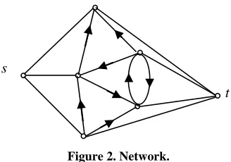
[image:4.595.339.503.84.199.2]t s
Figure 2. Network.
ther’s weight and all the edges of the cut set correspond- ing this vertex, its sign is its father’s sign times –1. Each still node’s weight equals to the union of its father’s weight and the tree’s weight whose root is this vertex and its sign is its father’s sign times –1.
5. Computational Complexity
The main part of the presented algorithm is “Algorithm Sub-tree”. It has two parts. One is Sub-trees Generation, the other is Weighted Sub-trees. The main work of “al- gorithm Sub-trees Generation” is to determine whether there exist edges between two sets. It at most needs
m 1
m 2
1 m m
1
2 comparison op-erations for each sub-tree. “Weighted sub-trees” runs in
O M
2m
18
2m 2
, where M is the number of terms in the last sym- bolic un-reliability expression. In fact, M is more smaller than . For example,the network in Figure 2, m = 18,
, but M = 151. For each of sub-trees, other operations at most take time. It takes
262144
O m
O n time to find all mincuts, where n is the number of nodes of a given network. It takes time to find each candidate child set. So the computational complex- ity of the presented algorithm is .
O m
O n m
3
M
6. Conclusion
This paper presents an efficient algorithm for evaluating the reliability of network based mincuts. The algorithm generates all the non-canceling terms in the unreliability expression. By the thought of “dynamic programming” method each vertex at most generates two generations children in every sub-tree. The number of vertices of the generated sub-trees are more smaller than the number of non-canceling terms in QG
s t, ’s expression. The algo- rithm has smaller time complexity.REFERENCES
[1] C. J. Colbourn, “The Combinatorics of Network Reliabil-ity,” Oxford University Press, New York, Oxford, 1987.
[3] J. A. Buzacott, “Node Partition Formula for Directed Graph Reliability,” Networks, Vol. 17, No. 2, 1987, pp. 227-240. doi:10.1002/net.3230170207
[4] J. A. Buzacott and S. K. Chang, “Cut Set Intersections and Node Partition,” IEEE Transactions on Reliability, Vol. 31, No. 4, 1982, pp. 385-389.
[5] A. Satyanarayana and A. Prabhakar, “New Topological Formula and Rapid Algorithm for Reliability Analysis of Complex Networks,” IEEE Transactions on Reliability, Vol. 27, No. 1, 1978, pp. 82-100.
doi:10.1109/TR.1978.5220266
[6] A. Satyanarayana and J. N. Hagstrom, “A New Algorithm
for Reliability Analysis of Multi-Terminal Networks,”
IEEE Transactions on Reliability, Vol. 30, No. 4, 1981, pp. 325-334. doi:10.1109/TR.1981.5221103
[7] L. C. Zhao and F. J. Kong, “A New Formula and an Al-gorithm for Reliability Analysis of Network,” Microelec-tronReliability, Vol. 37, No. 4, 1997, pp. 511-518.
[8] W. C. Yeh, “A Greedy Branch-and-Bound Inclusion-Ex- clusion Algorithm for Calculating the Exact Multi-State Network Reliability,” IEEE Transactions on Reliability, Vol. 57, No. 1, 2008, pp. 88-93.