-Network Computing Devices, Inc. 350 North Bernardo Avenue Mountain View
California 94043 (415) 694-0650
Email: [email protected]
NCD16
User's Manual
Part Number 9300034 February 1990 Printed in U.S.A.
Notice
The information contained in this document is subject to change without notice.
Network Computing Devices, Inc. shall not be liable for errors contained herein or for incidental or consequential damages in connection with the furnishing, performance, or use of this material.
This document contains information which is protected by copyright. All rights are reserved. No part of this document may be photocopied, reproduced, or translated to another language without the prior written consent of Network Computing Devices, Inc.
Copyright © 1990 by Network Computing Devices, Inc.
Trademarks
NCD16, NCD19, NCDnet, and XRemote arc trademarks of Network Computing Devices, Inc. X Window System, X, and XlI are trademarks of the Massachusctts Institute of Technology
DECnet, DECwindows, VMS, VAX, VT, and ULTRIX are trademarks of Digital Equipment Corporation Ethernet is a trademark of Xerox Corporation
UNIX is a registered trademark of AT&T
Sun Workstation and SunOS are trademarks of Sun Microsystems, Inc. PS/2 and PC/ AT are trademarks of IBM.
Warning!
This equipment generates, uses, and can radiate radio frequency energy, and if not installed and used in accordance with the instruction manual might cause interference to radio communications. This equipment has been tested and found to comply with the limits for a Class A computing device pursuant to Subpart
J
of Part 15 of FCC Rules, which are designed to provide reasonable protection against such interference when operated in a commercial environment. Operation of this equipment in a residential area is likely to cause interference in which case the user at his own expense will be required to take whatever measures might be required to correct the interference.This digital apparatus does not exceed the Class A limits for radio noise emissions from digital apparatus set out in the Radio Interference Regulations of the Canadian Department of Communications.
You can determine whether this equipment is causing interference by turning it off. If this equipment does cause interference to radio or television reception, you can try to correct the interference by using one or more of the following methods:
• Turn the television or radio antenna until the interference stops. • Move this equipment to one side or the other of the television or radio. • Move this equipment farther away from the television or radio.
• Plug this equipment into an electrical outlet that is on a different circuit from the television or radio. (That is, make certain this equipment and the television or radio are on circuits controlled by different circuit breakers or fuses.)
• Consider installing a rooftop television antenna with coaxial cable lead-in between the antenna and the television.
If necessary, you should consult an experienced radio/television technician for additional suggestions. You might find helpful the following booklet, prepared by the Federal Communications Commission:
"How to Identify and Resolve Radio-TV Interference Problems"
Table of Contents
Preface
Organization of this Manual ... i
How to Use this Manual ... i
Safety Considerations ... ii
1 A Quick Look at the NCD16 Introduction ... 1
Hardware and Software Components ... 2
Modes of Operation ... 3
2 Getting Started Introduction ... 5
Preinstallation Planning ... 6
Equipment Supplied ... 8
Unpacking and Inspection ... 9
Configuring the NCD16 Hardware ... 14
Testing Memory ... 27
Coprocessor ... 30
Assembling the NCD16 Components ... 31
Connecting the NCD16 Components ... 37
Connecting the NCD16 to a Network. ... 39
Connecting AC Power ... 41
Starting the Server ... 42
Establishing a Connection to a Host ... 45
3 X Window System Overview
Introduction ... .., ... 57
NCD16 X Display Server ... 59
Application Clients ... 60
Fonts ... 62
Color Database ... 64
Defaults and Resources ... 65
XHOST Security ... .., ... 66
4 Operating the NCD16 Introduction ... 67
Operating Controls ... .., ... 67
The Setup Key ... .., ... , ... 70
Setup Menus and Built-in Sessions ... 71
Warnings About Memory ... 121
5 Keyboards Introduction ... 123
Key Reassignment ... 124
6 Caring for Your NCD16 Introduction ... 141
Preventive Maintenance ... 141
Caring for the Keyboard ... 141
Cleaning. the Mouse ... 142
7 References NCO Documentation ... 143
Glossary
Appendix A: Specifications
Preface
This manual contains information you need to install, configure, and operate your NCD16. The NCD16 is an intelligent, graphics-oriented device which implements the XII Release 3 server protocol specification of the X Window System with selected Release 4 features, and operates over an Ethernet network or a serial port.
Organization of this Manual
This manual is organized into seven chapters, a glossary, and an appendix:
Chapter 1- A Quick Look at the NCD16 contains a description of the NCD16 and a list of equipment supplied.
Chapter 2 - Getting Started describes how to configure, assemble, and connect the NCD16, and how to power it up and log on to a host computer.
Chapter 3 - X Windows Overview provides an overview of the X Window System.
Chapter 4 - Operating the NCD16 explains setup windows and how to run CTERM, Telnet, and terminal emulation sessions.
Chapter 5 - Keyboards explains the keyboards used with the NCD16.
Chapter 6 - Caring for your NCD16 describes how to perform preventive maintenance and cleaning proced ures.
Chapter 7 - References lists documents that are available for reference. Glossary
Appendix A - Specifications describes features and characteristics of the NCD16.
How
to Use this Manual
If you have just taken delivery of the NCD16, you should read Chapters 1 and 2. Refer to Appendix A as necessary for specifications, to Chapter 2 if you need to change the hardware configuration, and to Chapter 4 for information on operating the NCD16.
To add memory, refer to Chapter 2. For routine maintenance and cleaning procedures, refer to Chapter 6.
Preface
We welcome any comments you may have concerning this manual. Address information including electronic mail and FAX is on the inside front cover.
Safety Considerations
This manual contains warning and caution symbols to denote operations which could cause injury to personnel or damage to equipment. Please do not ignore these symbols.
ii
Warning
The warning sign denotes a hazard. H calls attention to a procedure or prac-tice, which,
if not correctly performed or adhered to, could result in injury. Make sure you understand the indi*Cated conditions before proceeding with the procedure or practice.
Caution
The caution sign calls attention to an operating procedure or practice, which, if
not correctly performed or adhered to, could result in damage to or destruction of part or all of the product. Make sure you
1
A Quick Look at the NCD16
Introduction
The NCD16 network display station (or X terminal) is an advanced graphics terminal that works with a network of computers to provide a highly productive window environment. The NCD16 includes
• a high-resolution, bit-mapped display
• software that supports version 11 of the X Window System (or X) • a keyboard
• a three-button mouse
The NCD16 provides a window interface to a wide variety of X Window System client applications running on network-accessible hosts, such as Sun Workstations, V AX and UNIX minicomputers, and suppercomputers. It can initiate X Window System host sessions
or--through Telnet, CTERM, or serial sessions--access hosts that do not support X. NCDnet software, available as an option, allows the NCD16 to communicate over DECnet, while another optional package, XRemote, allows the NCD16 to communicate with remote hosts. The NCD16 has been designed and built based on standards. It supports not only the X Window System, but also Ethernet, TCP lIP (Transmission Control Protocol/Internet Protocol), and DECnet for superior network communications.
The NCD16 complements power with flexibility. An extensive set-up menu system lets you customize default settings and view diagnostic and network management information. A host-based configuration facility is provided to allow convenient, centralized configuration management. For typographic flexibility, eight different fonts are built into the NCDI6. Others can be dynamically loaded from hosts over the network.
You will find that the NCD16 and other members of the NCD family of X window displays are ideal for a wide range of applications, induding:
• Software development
• Computer-aided engineering, publishing, and design • Information retrieval
1: A Quick Look at the NCD16
Hardware and Software Components
The NCDI6 consists of the following hardware components:
• A high-resolution display monitor assembly including the system power supply • A base unit containing the digital electronics printed-circuit assembly (PCA) and
the Ethernet module • Akeyboard
• A three-button mouse
The software components for the NCD16 are: • Boot monitor
• X server, an executable module containing the XII server, operating system, and communications protocols (Internet protocol stack and NCDnet protocol stack or XRemote protocol stack).
• Host-loaded fonts (optional)
The NCD16 software components are distributed as follows:
Component Distributed as ...
Boot Monitor PROMs
X Server PROMs
QIC-24 cartridge
I/2-inch reel-to-rcel tape (1600 bpi) TK50 cartridge
Fonts X server tape
font tape
Modes of Operation
Modes of Operation
The NCD16 operates in one of ten modes: • X server over TCP lIP Ethernet
• X server over TCP ISLIP (Serial Line Internet Protocol) • X server over TCP lIP and DECnet
• X server over TCP lIP and DDCMP (Digital Data Communications Protocol) • X server over DECnet
• X server over DECnet and TCP ISLIP
• X server over DDCMP via serial cable • Telnet terminal over Ethernet
• ANSI RS-232-C terminal (serial terminal) • CTERM over Ethernet
The operational mode is selected in the setup menus. The setup menus can be recalled at any time with the Setup key. The setup menus have a number of menus and sessions for manual configuration, diagnostics, statistics, Telnet, CTERM, serial session, and network
management.
While in X server mode, the NCD16 can display X client windows from a variety of computers. The number of windows supported varies according to the application and the amount of RAM installed in the NCD16.
When running in the X server mode, you have the ability to open a Telnet session, CTERM session, or terminal session by switching to the setup menu. You can toggle between the X server mode or a session by pressing the Shift and Setup keys simultaneously to enter the most recently viewed setup menu, and by pressing the Setup key to return to X server mode. For a functional description of XRemote, the software that allows an NCD16 to communicate over a serial line, see the XRemote User's Manual.
2 Getting Started
Introduction
This chapter contains information that will allow you to install, configure, and operate the NCD16, including:
•
•
•
•
•
•
•
•
•
•
•
•
•
Preinstallation Planning Equipment Supplied Unpacking and Inspection Repacking for Shipment
Configuring the NCD16 Hardware Assembling the NCD16 Components Connecting the NCD16 Components Connecting the NCD16 to a Network Connecting AC Power
Starting the Server
Establishing a Connection to a Host Accessing the Auxiliary Serial Port Configuring NCD16 Software
Warning
2: Getting Started
Preinstallation Planning
Before installing the NCD16, you should perform the checklist below. You wiII need help from your system administrator. The NCD release notes are also a guide for the most current information.
• Components - Verify that you have all equipment (see Equipment Supplied). • Location - Decide on a suitabie location for the NCD16.
• Inform your system administrator of the foIlowing: a. The type of NCD display station - NCD16.
b. The Ethernet address of your NCD16. The Ethernet address can be found on the label on the bottom of the base unit. It contains 12 hexadecimal digits and should appear similar to the foIlowing:
OO:OO:A7:00:02:AB
With the Ethernet address, your system administrator can assign a network address, prepare a remote configuration file for your unit, and perform the steps to download your NCD16 if that's appropriate.
c. Your NCD16 License Key. If your unit is licensed for NCDnet, you will have received a License Pak with the unit. Your system administrator can enable NCDnet on your NCD16 via NCO's remote configuration capability. • Ask your system administrator the following:
a. What kind of network connection will you be using? The supported interfaces are a thin Ethernet (sometimes called 802.3 10Base2, or
Pre installation Planning b. How do you access the X clients? You can access a host using one or more of
the following methods: - X Display Manager (XDM) - Telnet
- NCDnet (CTERM) - XRemote
-SLIP
Your system administrator can tell you which of these facilities are available to you.
c. How do you modify your login environment? What to type once you begin an XDM session or log in to a host via the Telnet, CTERM, or serial session. (If
you use the Telnet, CTERM, or Serial session to start X applications, you will need to modify your login environment so that the X clients know what display to use.)
• Your system administrator will set up the following:
a. Download service - Perform the steps necessary to download your NCD16, if a download is appropriate.
b. Configuration service - Define a remote configuration file for your NCD16. This is optional. NFS or NCDnet require this service.
2: Getting Started
Equipment Supplied
The NCD16 consists of the following components:
Quantity Description
1 Monitor display unit with power cord
1 Base unit containing the electronics printed~circuit assemblies (PCAs)
1 User's Manual (this manual)
1 Documentation package
1 Keyboard
1 Three~button mouse
1 NCDnet license (optional)
Unpacking and Inspection
Unpacking and Inspection
The NCD16 components are contained in four boxes, packed in a single shipping box, as shown in Figure 2-1. Inspect the NCD16 components as described in the following paragraphs.
2: Getting Started
Shipping Container Contents
The units are packed in specially-shaped styrofoam protectors inside the shipping boxes. After unpacking the NCD16 components, inspect each item carefully for evidence of damage. If any item appears to be damaged, notify the shipping carrier and Network Computing Devices, Inc. (the address is contained on the title page of this manual), or the authorized representative from whom you purchased the NCD16. It is recommended that you retain the original shipping carton and packing material in case any NCD16 item has to be returned to Network Computing Devices.
If any item does not meet specifications or does not function properly, notify Network Computing Devices or your authorized representative immediately.
The NCD16 Hardware consists of five components:
• Display Monitor - See Figure 2-2
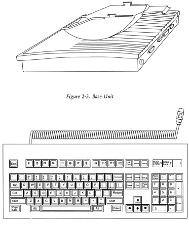
• Base Unit - See Figure 2-3
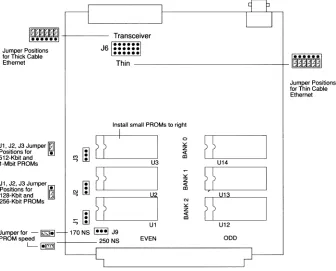
• Keyboard - See Figure 2-4
• Mouse - See Figure 2-5
• Power Cable
Unpacking and Inspection
2: Getting Started
Figure 2-3. Base Unit
~l
EJ
[J
[]
EJ
[~]~
8
E]
0
EJ
QJ0
@]
8
.~
0
Figure 2-4. Typical Keyboard
Unpacking and Inspection
Figure 2-5. Mouse
Repacking for Shipment
2: Getting Started
Configuring the NCD16 Hardware
The hardware configuration options consist of:
• Setting jumpers on the communications interface module in order to change from thin Ethernet to an attachment unit interface AUI (used for thick, twisted-pair, or fiber-optic Ethernet)
• Adding memory to the main module
If you are using thin Ethernet and do not need to add memory, no hardware configuration is required.
The NCD16 is shipped from the factory configured for thin cable Ethernet. However, if you are going to use an AUI and transceiver to connect the NCD16 to other than thin cable Ethernet, this configuration can be changed by a set of jumpers located on the
communications interface module.
14
Warning
Make sure that the AC power cord is not connected to the NCD16 display monitor.
Caution
Configuring the NCD16 Hardware
Removing the Communications Interface Module
The communications interface module is removed from the rear of the NCD16 base unit as described on the next page.
1. Remove the two screws holding the module in place in the base unit. See Figure 2-6.
Figure 2-6. Removing the Communications Interface Module Screws
2: Getting Started
Figure 2-7. Removing the Communications Interface Module
3. Slide the communications module out of the base unit.
Configuring the Jumpers
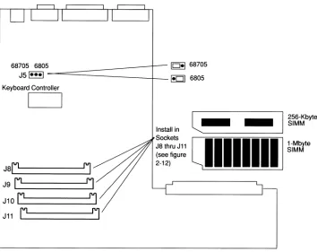
There are ten jumpers on the Ethernet communications module. Six of these are for
configuring the network interface, and the other four impact PROM size and speed. You do not need to change the jumpers unless you are using an external transceiver or are changing from a download to a PROM-based unit. See Figure 2-8 for the locations of the jumpers. The jumpers are described on the following pages.
Configuring the NCD16 Hardware
n"---_---'I
LJ
I~~~~~~II
+ - - - TransceiverJal···il
•••••• ••••••Jumper Positions for Thick Cable
Ethernet Thin ---+-llI~n;1]
11~~~~·!t
t~r'~r~ ~~~~ons Ethernet
Install small PROMs to right
H
I
I
0
H
J I. J2. J3 Jumper
Ii]
~~
zPositions for • «
512-Kbit and
'"
<III-Mbit PROMs ...., U3 UI4
H
I
~
U
JI. J2. J3 Jumper
~
z «Positions for
I
N <II1 28-Kbit and - ...., U2 LJI3
256-Kbit PROMs
~H
]
'"
H
~
z
«
::; <II
UI UI2
Jumper for -~- 170NS ~J9
PROM speed 250NS EVEN ODD
[image:28.540.107.443.140.411.2]L-~
2: Getting Started PROM Size Jumpers
Jumpers J1, J2, and J3 are used to indicate the size of the PROMs installed on the Ethernet communications module. Jumper J1 controls the BANK 2 sockets U1 and U12; J2 controls BANK 1 sockets U2 and U13; and jumper J3 controls the BANK 0 sockets U3 and U14. Setting the jumpers toward the bottom of the communications module (as viewed in Figure 2-8) sets them for 128-Kbit and 256-Kbit PROMs. Setting the jumpers toward the top of the
communications module sets the jumpers for 512-Kbit and 1-Mbit PROMs. The top of the communications module is the end where the external connectors TRANSCEIVER and THIN are mounted. See Figure 2-8.
PROM Speed Jumper
Jumper J9 is used to indicate the speed of the installed PROMs. See Figure 2-8 for the location of J9. The jumper is installed to the left for 170-ns PROMs, and to the right for 250-nsd PROMs (see Figure 2-8). PROMs may be mixed speeds of 170 and 250 nanoseconds. If any 250-ns PROMs are installed, the jumper must be set to the 2SO-ns position (to the speed of the slowest PROMs installed on the board).
Ethernet Jumpers
Jumper J6, which is a set of six jumpers, is used to configure the NCD16 for either a thin cable Ethernet network or for connecting a transceiver from the NCD16 to a thick cable, twisted-pair, or fiber optic Ethernet network.
Note that the unit is shipped from the factory with the jumpers configured for thin
Ethernet. Thus you do not need to configure the jumpers if you are going to use thin Ethernet. If you are using other than thin Ethernet, configure the jumpers for your network as follows:
18
1. Verify the type of network you will be using (the type will have been determined in the preinstallation planning).
2. Check the settings of the jumpers (refer to Figure 2-8).
Configuring the NCD16 Hardware PROM Sockets
PROMs are installed in pairs occupying the EVEN and ODD sockets (as shown in Figure 2-8) starting in BANK 0, then BANK 1, followed by BANK 2. A minimally-configured NCD16 must have two PROMs in BANK O. The PROMs are labeled to correspond with the BANK 0, BANK 1, BANK 2, EVEN, and ODD legends. There are two differences in the types of PROMs:
• Physical package size. The 27128, 27256, and 27512 PROMs are smaller and have fewer pins than 271001 PROMs. The outlines of the PROM sizes are shown in Figure 2-8. Large PROMs occupy the complete outline, while small PROMs must be installed to the right following the smaller outline.
• PROM speeds. PROMs come in 170-ns and 250-ns versions. Jumper J9 must be set according to the speed indicated on the PROM labels. In the case of mixed 170-and 250-ns PROMs, J9 must be set to the 250-ns position (the slowest speed). Boot PROMs are two small PROMs and occupy BANK O. If the unit is configured with server PROMs, four large PROMs will occupy BANK 1 and BANK 2.
Replacing the Communications Interface Module
Replace the communications interface module by sliding it into the base unit and replacing the two screws that lock the module into the unit.
Adding Additional Memory
2: Getting Started
68705 6805)
--=========J=
10-1 68705JSI"-I - 1-01 6805
Keyboard Controller
I
I
J S r ' - - - '
J9
Lr========~
J10
r'---J11
L.:r========::J
Install in Sockets J8 thru J11
l...
I
§f~~byte
..=::;;;;;:;;;;:;~~~ [image:31.540.125.479.117.398.2]ellllllill
~i~
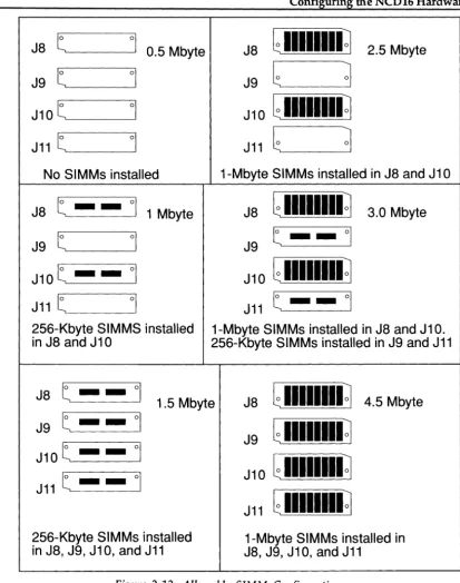
Configuring the NCD16 Hardware Optional RAM is furnished in O.5-Mbyte or 2-Mbyte increments. The O.5-Mbyte increment consists of two 256-Kbyte SIMMs, each containing two 256-Kbit by 4-bit RAMs. The 2-Mbyte increment consists of two l-Mbyte SIMMs, each containing eight l-Mbit by I-bit RAMs. The specifications for both SIMMs are: lOO-ns, low profile (l.l-inch high), 0.047 to 0.054 inch board thickness (0.05 inch nominal), 256K by 8 or 1M by 8.
Warning
Before performing the following procedure, make sure the AC power cord is not
connected to the NCD16.
Caution
2: Getting Started Accessing the Main PCA To gain access to the main PCA:
22
1. Remove all cables from the display monitor and the base unit.
2. If the display monitor and base unit are attached to each other, separate them as described below.
a. Tum monitor and base unit upside down and rest on a bench or other flat surface. (Be careful not to scratch the top of the NCD16.)
Configuring the NCD16 Hardware
Locking Tab Handle ...
Figure 2-10. Location of Locking Tab Handle
c. Lift up on the locking tab handle. The tabs should disengage. Press your fingers against the base unit while holding the locking tab handle up. Push base unit back and away from the front of the monitor and lift the base unit off the monitor .
2: Getting Started
4. With the base unit upside down, remove the two screws (near the front edge of the base) from the bottom of the base unit.
5. Lift slightly the front edge of the base unit's bottom cover and pull toward the front to release the plastic fingers at the rear of the base unit.
6. If it is necessary to remove any SIMMs, proceed as follows:
a. Place the base unit (with its cover removed) in front of you with the main PCA oriented as shown in Figure 2-9.
b. Select the SIMMs to be removed.
c. Use a small flat-blade screwdriver or similar instrument to release the locking tabs on each side of the SIMM socket (see Figure 2-11). Tilt the SIMM toward you and pull it out of the socket.
Locki ng Tabs
Figure 2-11. SIMM Socket Locking Tabs
Configuring the NCD16 Hardware
J8
t
°1
0.5 Mbyte
J8
G
IIIIIIII~
2.5 Mbyte
J9
t
°1
J9
G
~
J10
t
°1
J 1 0
G
IIIIIIII
~
J11
t
°1
J11
G
~
No SIMMs installed
1-Mbyte SIMMs installed in J8 and J1 0
J8
t - -
°1
1 Mbyte
J8
G
IIIIIIII~
3.0 Mbyte
J9 t
°1
J9 t - -
°1
J10t _ _
°1
J 10
G
IIIIIIII
~
J11 t
°1
J11 t -
-
°1
256-Kbyte SIMMS installed
1-Mbyte SIMMs installed in J8 and J1 O.
in J8 and J10
256-Kbyte SIMMs installed in J9 and J11
J8 t _ _
°1
1.5 Mbyte
J8
G
IIIIIIII~
4.5 Mbyte
J9 t _ _
°1
G
IIIIIIII~
J9
J10t -
_
°1
J 10
G
IIIIIIII
~
J11 t -
-
°1
J 11
G
IIIIIIII
~
[image:36.548.70.483.56.579.2]2: Getting Started
26
a. Place the base unit on a flat surface in front of you with the main peA oriented as shown in Figure 2-9.
b. Hold a SIMM by its edges and tilt it toward you. Push it firmly into a socket until you are sure it is seated all the way into the socket. Tilt the SIMM away from you until the two locking tabs, one on each end of the socket, click into place.
Testing Memory
Testing Memory
Whenever you add memory to the NCD16 or suspect that there may be problems with the terminal's memory, you should run the boot monitor's RAM March test on all banks of installed RAM.
To run this test, you need to enter the boot monitor. You can enter the boot monitor in one of two ways:
• Power up the terminal, then press the Esc key twice while the terminal is searching for an address or downloading the server.
• In the NCD16's setup menu, set "Boot X at Reset" to No, select "Save Power-On Values", then reset the terminal by double-clicking the setup menu's Reset Server button.
Once in the boot monitor, run the extended RAM test as outlined below for each bank of RAM installed. The SIMMs in J8 and J10 make up bank zero. Those in J9 and J11 make up bank 1.
1. At the boot monitor prompt (», type ex and press Return. 2. To select the RAM March test, type 8 and press Return.
3. Enter the appropriate starting access value for the bank being tested--400000 for bank zero or 600000 for bank one. Press Return.
4. Using the table below, enter the appropriate ending address value for the bank being tested, then press Return.
SIMM Size in bytes
256K
1M
Bank 0 (J8, JIO) Ending Address
47FFFF
5FFFFF
Bank 1 (J9, J11) Ending Address
67FFFF
2: Getting Started
28
5. Run the test once by pressing the Return key when asked for a test choice. The diagnostic code will display either
Pass - 00000001
to signify that the memory is good, a message of the form
was A5A5A4A5 sib A5A5A5A5 at 42C458 March test failure
if an error was detected. The first number is what the data was, the second is what was expected and the third is the memory address at which the discrepancy was detected.
6. If an error was detected, note the address of the failure (82C458 in the example above). Counting the bytes form zero to three and form left to right, note the byte or bytes in the test data that differ from the expected data (byte two in the example).
7. Using the table below, look up the first digit of the address at which the failure occurred and the byte that failed. The corresponding table entry gives the location of the failing SIMM.
Byte 400000 to 5FFFFF 600000 to 7FFFFF
0 J8 J9
1 JI0 Jll
2 J8 J9
3 JI0 Jll
8. In the example above using the column labeled "400000 to 5FFFFF" (for 42C458) and the row labeled 2 (discrepancy was in byte 2), the table reveals that the SIMM in J8 is failing.
9. Replace any failing SIMMs or remove the entire bank of SIMMs containing the failing SIMM, then rerun the memory test.
10. If you entered the boot monitor by pressing Esc twice and the test passed, you can reset the terminal by typing
rs
Testing Memory 11. If you entered the boot monitor by setting "Boot X at Reset" to No, you need to
2: Getting Started
Coprocessor
Assembling the NCD16 Components
Assembling the NCD16 Components
Warning
Make sure the AC power cord is not connected to the NCD16.
Attaching the Display Monitor
to
the Base Unit
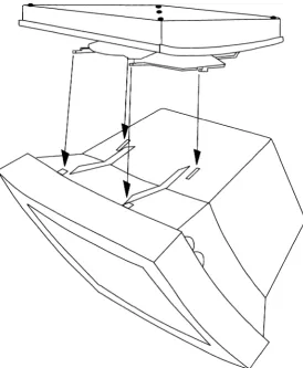
The display monitor is anchored to the base unit via a set of tabs and locking latches on the base unit.
To assemble the display monitor and base unit into a combined assembly:
2: Getting Started
32
Figure 2-13. Display Monitor, Bottom View
2. Note the locations of the slots on the bottom of the display monitor.
Assembling the NCD16 Components
Figure 2-14. Base Unit/Display Monitor Tab and Tab Socket Locations
[image:44.541.133.407.103.435.2]2: GeHing Started
Slide the Base Unit Forward
Until it Clicks into Place
Assembling the NCD16 Components
Caution
Make sure that the base unit and display monitor are locked together before you attempt to tum the assembly right side up.
2: Getting Started
Connecting the NCD16 Components
Connecting the NCD16 Components
The display monitor, keyboard, and mouse all connect to the base unit via connectors located on the rear panel of the base unit. The connectors are illustrated in Figure
2-17. Pinouts for all cables are described in Appendix A, Specifications.
Figure 2-17. Base Unit Connector Locations
Note
2: Getting Started
Caution
Do not connect the power cord to the NCD16 unless the monitor, keyboard, and mouse cables are all connected. Do not disconnect any of these cables when the NCD16 is powered on.
Connect the NCD16 components as follows:
1. Connect the display monitor cable to the monitor connector on the rear of the base unit. Be sure to tighten the retaining thumbscrews on the connector. 2. Connect the keyboard cable to the keyboard connector on the rear of the base
unit.
3. Connect the mouse cable to the mouse connector on the rear of the base unit. 4. Tighten the screws on all connectors.
Caution
Connecting the NCD16 to a Network
Connecting the NCD16 to a Network
The NCD16 connects to a thin cable Ethernet network via a BNC connector on the rear of the base unit or to an AUI cable via a IS-pin D connector (DB-IS) on the rear of the base unit. Note that an external transceiver is necessary when connecting to the DB-IS connector. For details on connecting the NCDI6 to a system or modem for XRemote, see the XRemote User's Manual.
Thin Cable Ethernet Installation
Connecting the NCD16 to a thin cable Ethernet network is accomplished with a BNC "T" connector as illustrated in Figure 2-18.
Thin Coaxial Cable Connection
BNC"T" \
Cable
---==y==
Ethernet Communications
Module
Cable Connected to Communications Module
Ethernet Communications
Module
2: Getting Started
1. As shown in Figure 2-17, connect the BNC "T" connector to the thin coaxial network cable at an appropriate location on the cable.
2. Connect the BNC "T" connector to the BNC connector on the back of the NCD16 base unit.
External Transceiver Cable Installation
As noted, if you are not using thin Ethernet, an external transceiver must be connected via an AUI cable. The connection to a typical external transceiver used with the NCD16 is
illustrated in Figure 2-18.
AUI Cable
Ethernet Communications
Module
~
Transceiver
,
-Figure 2-18. Connecting a Transceiver to the NCD16
Ethernet Cable
Connecting AC Power
Warning
Do not connect the power cord to the NCD16 unless the display monitor, keyboard, and mouse are all connected to the base unit connectors.
This product is equipped with a 3-wire grounding-type plug (a plug having a third (grounding) pin). This pin will fit only a grounding-type AC outlet.
If you are unable to insert the plug into the outlet, contact a licensed electrician to replace the outlet with a properly-grounded outlet.
6
[_~~
==>J
Do not defea t the purpose of the grounding-type plug.
Connecting AC Power
To apply power to the NCD16, make sure the display monitor power switch, located on the right side of the unit, is off. (The switch is off in the 0 position, and on in the 1 position.) Then plug the power cord into the back of the display monitor unit and into a wall outlet.
2: Getting Started
Starting the Server
When power is applied to the NCD16, the boot monitor tests the unit and a display similar to the following example will appear on the screen.
Boot Prom V2.1. 0
Testing available memory
Network controller passed
Keyboard controller
1.0 Mbytes
00:00:A7:00:02:AB
V2.00
Once the self-test has been successfully completed, the boot monitor (depending on configuration information stored in non-volatile RAM) will perform one of the following:
1. Enter the boot monitor. A > prompt is displayed. Note that no cursor is displayed in the boot monitor. The message will appear similar to the following:
Network Computing Devices NCD16 Boot Monitor
>
2. Load the server from PROM (only works on units with server PROMs). The message will read similar to the following:
Found server code at Ox40000
Unpacking text ... Unpacking data ... Done
3. Load the server via the network. The message will appear similar to the following:
Searching for IP address ...
Using IP address - 192.043.153.079
Starting the Server or
Searching for host ..
Loaded
This is followed by server initialization messages.
If the server is successfully loaded, it displays a "root-weave" window (a dark gray pattern), and, depending on configuration parameters, will display one of the built-in sessions such as the Telnet, CTERM, or Serial Session.
If only the root weave screen is displayed, the Setup key can be used to display the main setup menu. When the setup menus are displayed, pressing the Setup key returns the unit to the X server mode. When in X server mode, pressing the Shift and Setup keys
simultaneously enters the most recently viewed menu or session. In other words, the Setup key toggles between the setup menus or sessions and X server mode.
Should the server fail to load, an error message and prompt is displayed. Download can fail for a number of reasons, such as:
• You are not connected to the network. • No download available.
• The appropriate network code is not running on the download hosts. • Your Ethernet address has not been entered in the host data base.
Check your network connection. Then check the jumper settings. If everything appears to be correct, see your system administrator for assistance.
You can manually download the server using TFfP by entering the boot command:
where,
bt Xncd {NCO IP address} {host IP address}
Xncd is the optional server image
NeD IP address is your unit's internet address in hex or decimal dot notation (optional)
2: Getting Started
Or you can manually download the server using MOP by entering the boot command:
bd Xncd
where
Xncd - optional server image
If you cannot get the server to load, refer to the system administrator's manual for more information on the boot monitor, or see your system administrator for assistance.
To boot the server from PROMS use the command:
bp
To use X you must first create an authenticated connection to a host. This can be done using the X Display Manager (XDM) or by logging into a host. On the NCD16 you can log into a host using the Telnet, Serial, or CTERM sessions. The following paragraphs describe using XDM or host login to start X clients.
Establishing a Connection to a Host
Establishing a Connection to a Host
There are several ways to establish an initial connection with a host system to allow applications to be run on the NCD19.
• X Display Manager • Telnet
• NCDnet using CTERM • XRemote
• SLIP
2: Getting Started
Starting an
XDM
Session
The XDM login window may be displayed over the root-weave window when the server starts as shown in Figure 2-20. This depends on configuration parameters. If there is no XDM login window displayed and you want to use XDM, press the Setup key and select the X Server Parameters menu. In the lower portion of that setup menu you will find the XDM Parameters section. These parameters control XDM on the NCD16. See Chapter 4, Operating the NCD16, for further information.
Figure 2-20. XDM Login Window
Once the XDM login window appears, log in by typing your user name followed by a return and your password followed by a return. This will cause an XDM session to be started for you
Establishing a Connection to a Host
by executing your .xsession file (found in your home directory), or by starting an xtermif you have no .xsession file. If the last command in your .xsession file exists the system and the session is terminated. Consult your system administrator if you have trouble.
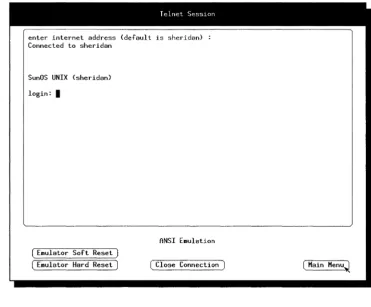
Starting a Telnet Session
The Telnet session window may be displayed over the root-weave window when the server starts (see Figure 2-21). This depends on configuration parameters. If there is no Telnet session displayed and you need to use Telnet, press the Setup key and select the Telnet session. See Chapter 4, Operating the NCD16, for further information.
lelnpt Se~~.'!ol)
enter internet address (default is sheridan> Connected to sheridan
SunOS UNIX (sheridan> login: I
ANSI E.ulalion
2: Getting Started
This allows you to log in to a host that supports Telnet and start an X client on your NCD16. You must first connect to the host system. The prompt looks like:
enter internet address (default is xyz):
To choose the default host, simply press Return. Otherwise, specify a host with either IP addr - decimal-dot notation (i.e., 192.43.153.16)
or
host -host name
You can use a host name if your network provides a name service. Consult your system administrator if you have trouble. You can then log in to the host.
Starting an X Client
After logging in you must inform potential X clients of your server address. For example, on UNIX systems:
%
setenv DISPLAY NCDhost:O
This sets the DISPLAY variable in your environment. NCDhost is your unit's host name assigned by the system administrator in the host data base. If you don't know your host name, or host name service is not available on your network, you can enter your internet address (available in the Network Parameters setup window).
You can then start a client such as XTERM:
%
xterm
&
or a window manager, such as uwm:
% uwm
&
Establishing a Connection to a Host
Starting with DECnet
NCDnet is a licensed option that allows your NCD16 to access DECnet. In order to use NCDnet the license key must be installed, and then you may connect to a DECnet host using CTERM.
License Key Installation
Normally your system administrator will install your license key for you via remote configuration. You can verify your license key by selecting the Licenses Features setup menu. (This menu is described in Chapter 4, Operating the NCD16.) If NCDnet has been
installed, the menu should indicate:
Licensed Features:
NCDnet
If the NCDnet license key has not been installed, you can install it by entering the 12-letter license key found on your License Pak shipped with your unit in the License Key field in the setup menu. First select the License Key field by clicking with the left mouse button. You may use either upper or lower case to enter the key followed by pressing the return key. If the key is correct, NCDnet will appear as a licensed feature. Then go to the main menu and save the current configuration in NVRAM. The License Key field will remain visible until you reboot your unit.
If the license key is incorrect, Bad Key will appear on the screen. Contact your system administrator or NCD if you have a problem with the license key.
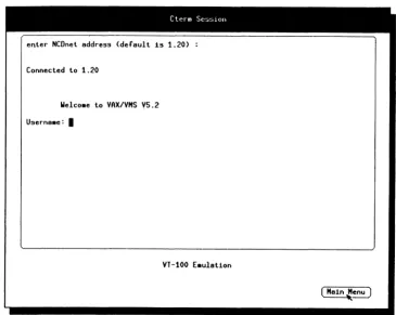
Starting a CTERM Session
The CTERM session is only available if the NCD16 has been configured with the correct license key to allow the use of NCDnet.
The CTERM session might be displayed over the root-weave when the server starts; this depends on configuration parameters. If there is no CTERM session displayed and you need to use CTERM, press the Setup key and select the CTERM session. See Chapter 4, Operating the NCD16, for additional information.
If the CTERM session menu choice is not present, there are two possible causes: 1. You are not running the correct version of the server.
2: Getting Started
CleT m Se~~>lon
,
e~ter NCDnet address (default 1s 1.20)
Connected to 1.20
Welco.e to VAX/VMS V5.2
Userna.e: I
[image:61.541.85.450.100.391.2]VT-100 E.ulat1on
Figure 2-21. CTERM Session Menu
The CTERM session allows you to log in to a host that supports CTERM and start an X client on your NCD16.
First you must connect to the host system. The prompt in the CTERM session looks like:
enter NCDnet address (default is xyz):
If the system you want to connect to is xyz, simply press Return. If you do not see a default, like xyz, in the prompt you will have to type a host name or address. A host name is the DECnet node name of the host. A host address is simply the DECnet node address (e.g.,
Establishing a Connection to a Host You can only use a host name if the NCD16 has been configured with a list of name-to-address pairs. See your system administrator if you have trouble.
Once you have selected the host, log in.
If the host is a VMS machine in which an NCD boot or font tape has been installed, the account NDS_LOGIN provides the simplest means of starting the DECwindows system. This account has no password and only allows access to start DEC windows on a remote X device. Log in as NDS_LOGIN and then exit the setup windows by pressing the Setup key. Mter a short delay, you should see the DECwindows login banner.
Once the DECwindows login banner appears, you can log in and you'll be running DECwindows on your NCD16.
If the host is an UL TRIX machine, simply log in to the host and follow the directions in the paragraph "Starting an X Client".
Using XRemote
XRemote is an optional software product that allows the NCD16 to run the X Windows System protocol efficiently over a serial connection.
With the addition of an XRemote PROM set, the NCD16 can be configured to use the X server using a serial line rather than Ethernet using the XRemote communication and compression protocols.
2: Getting Started
Using the X
Server Over
rep
and SLIP
The NCD16 can be configured to use the X server using a serial line rather than Ethernet by using the TCP protocols over SLIP (Serial Line Internet Protocol). The use of SLIP varies widely with the host or gateway providing the SLIP service at the other end of the serial line.
In order to use SLIP follow the steps below:
52
1. Configure the serial port. Go to the Serial Parameters setup window. The suggested configuration of the Auxiliary Port Parameters is as shown on the next page.
Suggested
Parameter Value Comments
Data Bits 8 Required
Stop Bits 1 Must match receiver's configuration Parity None Must match receiver's configuration
Handshake DTR/DSR Choose to match modem or other equipment orRTS/CTS
Baud Rate 38400 Choose to match modem or other equipment; as high as possible
2. Configure the serial port for a serial session by selecting Terminal Session on the Use Port for field.
3. Go to the Serial Session window. Establish the connection to the receiving equipment. If you are using a modem, dial the telephone and make a connection to the receiving equipment's modem. Then if you are using a gateway, establish a connection with the gateway. Otherwise, log into the SLIP host.
4. Set the receiving equipment into 'SLIP' mode. On some UNIX operating systems this might involve the slattach command. For gateways, there might be a SLIP
Establishing a Connection to a Host 5. Set the system internet address. Go to the Protocol Parameters window and
enter your unit's decimal-dot internet address in the System's IP Address field. This address can either come from your system administrator or may have been issued and displayed to you by your gateway when the receiver entered 'SLIP' mode.
If your unit's internet address is unchanging you can avoid step 5 in the future by saving the configuration in NVRAM.
6. Set the gateway internet address. Set the receiver's decimal-dot internet address in the Default Gateway field in the Protocol Parameters window. If the receiver's internet address is unchanging you can avoid this step in the future by saving the configuration in NVRAM.
7. Switch serial port. The serial port must be changed to be the unit's network connection, disconnecting Ethernet and connecting to the serial port. Go to the Serial Parameters window and select Network Interface on the Use Port for
field. This reconfiguration takes place immediately.
2: Getting Started
Accessing the Auxiliary Serial Port
The NCD16 can be configured to allow host computer access to the Auxiliary serial port on the back of the NCD16.
The serial port is accessed using a utility that opens a connection to a well known TCP port number on the NCD16. This provides a bidirectional connection on which data transmitted to the NCD16 is sent out on the serial port and data arriving on the serial port is
transmitted to the host. The Serial Port Parameters are used to control the configuration and can be set directly through the Serial Port Parameters or by remote configuration.
Sources for a sample application are provided on all UNIX system distribution tapes provided by NCD. See your system administrator for more information on this sample utility.
Configuring NCD16 Software
Configuring NCD16 Software
There are two methods for configuring NCD16 software: remote configuration and Setup menus. Many of the configuration parameters are saved in non-volatile memory (NVRAM), which allows the user or system administrator to set values once upon installation and then be free from these details when the NCD16 is booted in the future.
Remote configuration allows the system administrator to create ASCII configuration files for one or more NCD16s and then centrally administer the configuration information without having to physically contact each NCD16. The file
lusr/lib/Xll/ncd/configs/<NCD
IP address>
or
NCD_CONFIGS: [000000] AA_NNNN.DAT
is read from a host at the time the server is initialized.
<NCD IP address> is the NCD16's uppercase hexadecimal internet address. For example, a unit with internet address 192.43.153.57 translates to a file name C02B9939.
AA_NNNN.DAT is a file whose name is composed of the DECnet area (AA) and node (NNNN) number at the NCD16. For example, if the DECnet address is 1.25, the configuration file name is 01_0025.DAT.
Should the above file not exist, the server also tries
lusr/lib/Xll/ncd/configs/ncd_std
or
NCD_CONFIGS: [000000] NCD_STD.DAT
as a configuration file. If no configuration file exists, the server then uses parameters found inNVRAM.
2: GeHing Started
Refer to the system administrator's manual for more information. The set of remote configuration parameters is described there, along with the description of the file format. Chapter 4, Operating the NCD16, contains a complete description of the setup menus.
3
X
Window System Overview
Introduction
This chapter contains a brief overview of the X Window System. It is assumed that you are familiar with the X Window System, and the brief overview presented here should be considered merely as a refresher. Refer to the X Window System User's Guide for Version 11, by
Tim O'Reilly, Valerie Quercia, and Linda Lamb, published by O'Reilly and Associates, Inc., for a complete discussion of the X Window System. This document is available at computer book stores.
The X Window System, also referred to as "X" in this manual, was originally developed by MIT in the C programming language for workstations running UNIX; however, it is not confined to a particular operating system or to specific hardware. For example, X will run under many variations of UNIX, such as 4.3BSD UNIX, ULTRlX-32, etc.; and other operating systems such as V AX/VMS and MS/OOS. In addition, any computer hardware running one of these various operating systems can support the X Window System.
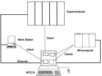
The X Window System is divided into two parts: the display server, and application clients.
3: X Window System Overview
Supercomputer
Client
Client Minicomputer
[image:69.540.102.452.101.362.2]Ethernet
NCD16 X Display Server
NCD16
X
Display
Server
The X display server implemented by the NCD16 performs the following functions: • Supports the X Window System protocol, which allows X clients (application
programs residing on a host computer) to communicate with the NCD16.
• Performs the network tasks required for the NCD16 to connect to host computers over Ethernet or RS-232-C.
• Controls the keyboard and mouse interfaces.
3: X Window System Overview
Application Clients
Application clients, also referred to merely as clients, are programs which perform a large variety of tasks and may reside on one or most host computers. The clients described here are part of the MIT distribution; brief descriptions are provided for the clients most tied to controlling the NCD16:
xdm xlsfonts uwm twm xterm xset xfd bdftosnf xfed xmodmap
X Display Manager. This is a login-style daemon used to initialize the connection between the NCD16 and a host system
Displays fonts available to the server
UNIX Window Manager. This is used to move, resize, create icons and manipulate windows on the display
The Window Manager. An alternative window manager, part of the X contributed distribution.
Terminal emulator
User preference utility. This is used to control server parameters such as font paths, bell volume, key click, and mouse acceleration
Displays a font
BDF (Bitmap Distribution Format) to SNF (Server Normal Form) font compiler. This program converts fonts from the portable format - BDF, which is ASCII plain text, to the server internal format. NCD distributes a number of fonts in SNF, which can be used by the NCO server. By using the NCO-provided bdftosnf, other fonts can be converted to NCO format.
Font editor. Can be used to modify BDF files. This client is part of the X contributed distribution.
xev
xsetroot
Application Clients
Displays contents of X events. Useful for experimenting with keyboard key settings, mouse buttons and mouse border crossings
3: X Window System Overview
Fonts
The characters and cursors seen on the display station are accessed as fonts. A font is a collection of pre-rendered characters of certain style and size. Clients explicitly ask for a font, and then ask the server to display individual characters (or more properly, in X, glyphs). The NCD server comes with eight built-in fonts and is dependent on host services for dynamic font service to satisfy other client font requests. Fonts are maintained in formatted data files on one or more hosts. The NCD server opens font files and reads in the data when the font is initially accessed. These files are kept in a format known as Server Normal Form (sNF). In addition to the font files themselves there are two additional files:
fonts.dir
andfonts.alias.
These files are used to map font names to files. The fonts.dir file maps font names to files while fonts.alias is a secondary mechanism to provide alternative fonts. If an application asks for a particular font by name, and that font is not available, a fonts.alias file can be created to map to a font name that does exist.
At the time the NCD server is initialized, a default font path list is scanned, and the fonts.dir and fonts.alias files found in each font directory are opened, read and added to the server's internal tables. Then when a client requests a font, the tables are checked, and if the font name is found the corresponding font file is opened and read into the server's internal font
database. In addition, the server has fonts built in internally to assist with initial installation, or in case it is not possible to obtain font service from a host machine. The internal fonts are:
l0x20 6xlO 8x13 9x15 cursor fg-22 By default the NCD server uses a font path set to:
built-ins
lusr/lib/Xll/ned/fonts/mise
62
lusr/lib/Xll/ncd/fonts/l00dpi
lusr/lib/Xll/ncd/fonts/75dpi
or on VMS
built-ins
ned_fonts: [OOOOOOJ mise
ned_fonts: [OOOOOOJ 700DPI
ned_fonts: [OOOOOOJ 750DPI
Fonts
This search path (or order) can be changed by the use of the xset client or by remote
configuration. For example, to add a directory of fonts to the search path, type the following command:
% xset
fp+lusr/lib/Xll/ncd/fonts/oldxll
The current font path may be displayed by typing:
%
xset
qThe font path, by default, is reset to the default whenever the server is reset. The server is reset whenever the last client disconnects. This can be overridden in the NCD server by selecting the Retain X Settings option in the Setup parameters. Failures of the font mechanism
3: X Window System Overview
Color Database
Color intensities are maintained in the file:
lusr/lib/Xll/ned/rgb.txt
or on VMS
ned_fonts: [000000] rgb.txt
This file is opened when the NCD16 server is initialized, and contains a list of color names and their black or white alias. This allows some color applications to run on the NCD16 monochrome server.
Defaults and Resources
Defaults and Resources
The X clients use a large number of defaults - known as resources in X - in order to pass information to a client other than on the command line. These defaults are contained in a file called .Xdefaults, which is used by clients such as xterm. This file is typically read by the
application when it is initialized. In addition to the Xdefaults file, the program xrdb can be
used to maintain a server resource database. By maintaining the database in the server, multiple copies of the Xdefaults file do not have to be maintained on each client host machine.
An example of a use of the Xdefaults file is xterm's usage of backing store. In order to inform an xterm client that backing store is to be set to when mapped, the following line is added to
the Xdefaults file in your home directory:
xterm*backingStore: whenmapped
Another useful file is the .uwmrc file. This file is opened and read when the uwm window
3: X Window System Overview
XHOST Security
The NCD16 normally allows any host to connect to the display station. The xhost client program can restrict access to the NCD16. Xhost can create and manipulate the access control list and can also enable and disable access control restriction. Both the access control list and the enabling and disabling of access control are maintained inside the NCD server.
One side effect of the use of xhost for access control is that after enabling access control using xhost, you may not be able to disable access control using the xhost client. This is due to the fact that once access control is in effect, existing client connections are unaffected, but new connections are only permitted to the hosts in the access control list. When xhost is run it attempts to make a connection.
If the host running the xhost client program is not on the access list, and access control is enabled, xhost fails. Be sure to include the host running the xhost program on the access control list before enabling access control.
Using xhost for access control on the NCD16 is only a partial solution to access control. The problem is that until xhost is run, any client program can connect to the NCD16. This
problem can be circumvented by providing the access control list and enabling access control via remote configuration. This ensures that access control will be enabled as the server comes up, and will prevent unauthorized connections. See the system administrator manual
regarding use of this feature.
4
Operating the
NCD16
Introduction
The NCD16 is operated via a set of "menus" that appear on the display. These menus are explained in this chapter. Also covered here are the operating controls for the unit.
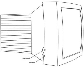
Operating Controls
The operating controls on the NCD16 are a power switch, located on the lower right of the display monitor bezel; and brightness and contrast controls, located on the lower left of the display monitor bezel.
The power switch is used to apply power to the NCD16.
Brightness and Contrast Controls
4: Operating the NCD16
Figure 4-1. NCD16 Controls
The brightness control adjusts the light level of "black" video - the brightness of the screen background. The contrast control adjusts the level of "white" video - the brightness of the screen foreground. The labeling of these controls is non-intuitive. One would think that brightness (and the use of the sun symbol) adjusts how white the screen is, not how black it is. In order to avoid confusion, the terms "white" and ''black'' video or "whiteness" and ''blackness'' are used to describe how these controls operate.
Normal Control Setting
Control Knob Position Brightness Minimum Contrast Center Detent
Operating Controls
The contrast control is adjusted to set the level of white to suite personal taste. The brightness control is not normally used, and exists to satisfy the European ergonomic specifications (described below). Increasing contrast increases brightness while decreasing focus. This is an inherent feature of monitor design. The best focus is achieved at minimum whiteness. You can adjust contrast to the optimum tradeoff between whiteness and focus.
As contrast increases, whiteness increases until the display ''blooms''. This is the point at which display quality is no longer acceptable. You can then decrease the contrast control below the bloom, setting the monitor to its maximum whiteness. The maximum whiteness position varies as the display ages, and consequently can not be preset by the factory.
European Control Setting
Control Knob Position
Brightness Center
Contrast Center Detent
4: Operating the NCD16
The Setup Key
The NCD16 has a comprehensive set of setup menus that allows manipulation of most configuration parameters. In addition, there is a set of built-in sessions - such as a Telnet session.
There is a special key, the Setup key, on the keyboard that provides access to these menus and sessions.
When the screen is displaying only X Windows information, depressing the Setup key will cause the Main Menu to be displayed. Pressing the Setup key again causes the displayed menu or session to be removed from the screen.
When the screen is displaying only X Windows information, and the Setup key is pressed in conjunction with the the Shift key, the last displayed menu or session is displayed again. In this way you can toggle between X Windows and one of the setup menus or built-in sessions. Pressing both keys while in a menu has the same effect as pressing the Setup key alone -you return from the current menu or session.
Operating Controls
Setup Menus and Built-in Sessions
The NCD16 has a set of menus and sessions that allow you to do several things: • Manipulate most configuration parameters
• View many of the network statistics • View diagnostic messages
• Connect to another network node via standard protocols
The Main Menu provides access to all of the underlying menus and sessions. From the Main Menu you can access parameters for:
•
User preferences•
The network•
The network protocols•
The serial port•
Licensed featuresIn addition, the Main Menu provides access to the diagnostic session, which displays all warning and error messages produced by the NCD16, as well as the following management menus useful for diagnosing problems:
• Network statistics • Protocol specific statistics
• Protocol specific management data • Network management
The Network Management menu provides such diagnostic and management utilities as: • A network test utility (ping or MIRROR)
4: Operating the NCD16
From the Main Menu you can access the following built-in sessions: • Telnet
• CTERM
• Serial
Many of the windows contain oval buttons. Moving the cursor over a button and clicking any mouse button causes a change to the selection displayed inside the button. Some buttons cycle through a selection of options, while other buttons require typing to fill in the required information. For buttons that cycle, pressing the left mouse button cycles "down", while the middle and right buttons cycle "up" through the selections. At the Main Menu level, clicking on one of the submenu buttons displays the selected submenu.
The values displayed in the windows are the operational values used by the server. These values can come from NVRAM (Non-Volatile RAM) or be overridden by a remote
configuration loaded via the network. Any fields modified in the windows take effect: • Immediately, or
• On exit of the setup windows, or • On server reset.
Operating Controls
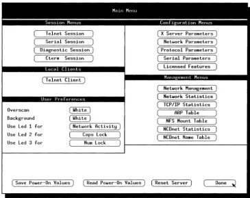
Main Menu
The Main Menu is shown in Figure 4-2. The parameters are explained below.
Overscan
Telnet Session Serial Session Diagnostic Session)
Cterm Session
Local Cllents
( T elnet Client)
User Preferences
Malf) Menu
Background Use Led 1 for Use Led 2 for Use Led 3 for
( Netldork Activity) Caps Lock
Num Lock
( X Server Parameters) ( Netldork Parameters) ( Protocol Parameters)
Serial Parameters ( Licensed Features)
Mana ernent Menus
Netldork Management) Netldork Statistics) TCP/IP Statistics
ARP Table NFS Mount Table NCDnet Statistics NCDnet Name Table
[image:84.544.93.458.160.449.2]( Save POlder-On Values ) ( Read POlder-On Values) (Reset Server) Done ~
Figure 4-2. Main Menu
4: Operating the NCD16
Reset Server
Done
displayed in the windows. Oicking on this field overrides values delivered by the network.
Clicking here restarts the unit. A second click is required to confirm the reset.
Exits setup menu.
Session Menus
Session Menus are "terminal-like" windows. The types of sessions are described briefly below and in greater detail in subsequent sections.
Telnet Session
Serial Session
Diagnostic Session
CTERM Session
Selects Telnet ANSI terminal emulation.
Selects an ANSI terminal emulation window using auxiliary RS-232-C port.
Selects console output window, displays memory information.
Selects CTERM session, which provides VT100 terminal emulation.
User Preferences
These are visual changes that are stored in NVRAM. Changes made here can be stored in NVRAM by clicking "Save Power-On Values" in the Main Menu. These buttons cycle through a selection of options. The options are listed first, with the first option being the factory setting. Each option change goes into effect immediately when the button is clicked, allowing you to assess the change before saving in NVRAM. The options available are described below.
Overscan
Backgr