NONRESIDENT
TRAINING
COURSE
SEPTEMBER 1998
Navy Electricity and
Electronics Training Series
Module 9—Introduction to
Wave-Generation and Wave-Shaping
DISTRIBUTION STATEMENT A: Approved for public release; distribution is unlimited. Although the words “he,” “him,” and
PREFACE
By enrolling in this self-study course, you have demonstrated a desire to improve yourself and the Navy. Remember, however, this self-study course is only one part of the total Navy training program. Practical experience, schools, selected reading, and your desire to succeed are also necessary to successfully round out a fully meaningful training program.
COURSE OVERVIEW: To introduce the student to the subject of Wave-Generation and Wave-Shaping
Circuits who needs such a background in accomplishing daily work and/or in preparing for further study.
THE COURSE: This self-study course is organized into subject matter areas, each containing learning
objectives to help you determine what you should learn along with text and illustrations to help you understand the information. The subject matter reflects day-to-day requirements and experiences of personnel in the rating or skill area. It also reflects guidance provided by Enlisted Community Managers (ECMs) and other senior personnel, technical references, instructions, etc., and either the occupational or naval standards, which are listed in the Manual of Navy Enlisted Manpower Personnel Classifications and Occupational Standards, NAVPERS 18068.
THE QUESTIONS: The questions that appear in this course are designed to help you understand the
material in the text.
VALUE: In completing this course, you will improve your military and professional knowledge. Importantly, it can also help you study for the Navy-wide advancement in rate examination. If you are studying and discover a reference in the text to another publication for further information, look it up.
1998 Edition Prepared by FTCM Earl Oaks
Published by
NAVAL EDUCATION AND TRAINING PROFESSIONAL DEVELOPMENT
AND TECHNOLOGY CENTER
Sailor’s Creed
“I am a United States Sailor.
I will support and defend the
Constitution of the United States of
America and I will obey the orders
of those appointed over me.
I represent the fighting spirit of the
Navy and those who have gone
before me to defend freedom and
democracy around the world.
I proudly serve my country’s Navy
combat team with honor, courage
and commitment.
TABLE OF CONTENTS
CHAPTER PAGE
1. Tuned Circuits ... 1-1 2. Oscillators... 2-1 3. Waveforms and Wave Generators... 3-1 4. Wave Shaping... 4-1
APPENDIX
I. Glossary... AI-1 II. Square and Square Roots Table... AII-1
NAVY ELECTRICITY AND ELECTRONICS TRAINING
SERIES
The Navy Electricity and Electronics Training Series (NEETS) was developed for use by personnel in many electrical- and electronic-related Navy ratings. Written by, and with the advice of, senior technicians in these ratings, this series provides beginners with fundamental electrical and electronic concepts through self-study. The presentation of this series is not oriented to any specific rating structure, but is divided into modules containing related information organized into traditional paths of instruction. The series is designed to give small amounts of information that can be easily digested before advancing further into the more complex material. For a student just becoming acquainted with electricity or electronics, it is highly recommended that the modules be studied in their suggested sequence. While there is a listing of NEETS by module title, the following brief descriptions give a quick overview of how the individual modules flow together.
Module 1, Introduction to Matter, Energy, and Direct Current, introduces the course with a short history
of electricity and electronics and proceeds into the characteristics of matter, energy, and direct current (dc). It also describes some of the general safety precautions and first-aid procedures that should be common knowledge for a person working in the field of electricity. Related safety hints are located throughout the rest of the series, as well.
Module 2, Introduction to Alternating Current and Transformers, is an introduction to alternating current
(ac) and transformers, including basic ac theory and fundamentals of electromagnetism, inductance, capacitance, impedance, and transformers.
Module 3, Introduction to Circuit Protection, Control, and Measurement, encompasses circuit breakers,
fuses, and current limiters used in circuit protection, as well as the theory and use of meters as electrical measuring devices.
Module 4, Introduction to Electrical Conductors, Wiring Techniques, and Schematic Reading, presents
conductor usage, insulation used as wire covering, splicing, termination of wiring, soldering, and reading electrical wiring diagrams.
Module 5, Introduction to Generators and Motors, is an introduction to generators and motors, and
covers the uses of ac and dc generators and motors in the conversion of electrical and mechanical energies.
Module 6, Introduction to Electronic Emission, Tubes, and Power Supplies, ties the first five modules
together in an introduction to vacuum tubes and vacuum-tube power supplies.
Module 7, Introduction to Solid-State Devices and Power Supplies, is similar to module 6, but it is in
reference to solid-state devices.
Module 8, Introduction to Amplifiers, covers amplifiers.
Module 9, Introduction to Wave-Generation and Wave-Shaping Circuits, discusses wave generation and
wave-shaping circuits.
Module 10, Introduction to Wave Propagation, Transmission Lines, and Antennas, presents the
Module 11, Microwave Principles, explains microwave oscillators, amplifiers, and waveguides.
Module 12, Modulation Principles, discusses the principles of modulation.
Module 13, Introduction to Number Systems and Logic Circuits, presents the fundamental concepts of
number systems, Boolean algebra, and logic circuits, all of which pertain to digital computers.
Module 14, Introduction to Microelectronics, covers microelectronics technology and miniature and
microminiature circuit repair.
Module 15, Principles of Synchros, Servos, and Gyros, provides the basic principles, operations,
functions, and applications of synchro, servo, and gyro mechanisms.
Module 16, Introduction to Test Equipment, is an introduction to some of the more commonly used test
equipments and their applications.
Module 17, Radio-Frequency Communications Principles, presents the fundamentals of a
radio-frequency communications system.
Module 18, Radar Principles, covers the fundamentals of a radar system.
Module 19, The Technician's Handbook, is a handy reference of commonly used general information,
such as electrical and electronic formulas, color coding, and naval supply system data.
Module 20, Master Glossary, is the glossary of terms for the series.
Module 21, Test Methods and Practices, describes basic test methods and practices.
Module 22, Introduction to Digital Computers, is an introduction to digital computers.
Module 23, Magnetic Recording, is an introduction to the use and maintenance of magnetic recorders and
the concepts of recording on magnetic tape and disks.
Module 24, Introduction to Fiber Optics, is an introduction to fiber optics.
Embedded questions are inserted throughout each module, except for modules 19 and 20, which are reference books. If you have any difficulty in answering any of the questions, restudy the applicable section.
Although an attempt has been made to use simple language, various technical words and phrases have necessarily been included. Specific terms are defined in Module 20, Master Glossary.
Considerable emphasis has been placed on illustrations to provide a maximum amount of information. In some instances, a knowledge of basic algebra may be required.
Throughout the text of this course and while using technical manuals associated with the equipment you will be working on, you will find the below notations at the end of some paragraphs. The notations are used to emphasize that safety hazards exist and care must be taken or observed.
WARNING
AN OPERATING PROCEDURE, PRACTICE, OR CONDITION, ETC., WHICH MAY RESULT IN INJURY OR DEATH IF NOT CAREFULLY OBSERVED OR FOLLOWED.
CAUTION
AN OPERATING PROCEDURE, PRACTICE, OR CONDITION, ETC., WHICH MAY RESULT IN DAMAGE TO EQUIPMENT IF NOT CAREFULLY OBSERVED OR FOLLOWED.
NOTE
INSTRUCTIONS FOR TAKING THE COURSE
ASSIGNMENTS
The text pages that you are to study are listed at the beginning of each assignment. Study these pages carefully before attempting to answer the questions. Pay close attention to tables and illustrations and read the learning objectives. The learning objectives state what you should be able to do after studying the material. Answering the questions correctly helps you accomplish the objectives.
SELECTING YOUR ANSWERS
Read each question carefully, then select the BEST answer. You may refer freely to the text. The answers must be the result of your own work and decisions. You are prohibited from referring to or copying the answers of others and from giving answers to anyone else taking the course.
SUBMITTING YOUR ASSIGNMENTS
To have your assignments graded, you must be enrolled in the course with the Nonresident Training Course Administration Branch at the Naval Education and Training Professional Development and Technology Center (NETPDTC). Following enrollment, there are two ways of having your assignments graded: (1) use the Internet to submit your assignments as you complete them, or (2) send all the assignments at one time by mail to NETPDTC.
Grading on the Internet: Advantages to
Internet grading are:
• you may submit your answers as soon as you complete an assignment, and
• you get your results faster; usually by the next working day (approximately 24 hours).
assignments. To submit your assignment answers via the Internet, go to:
http://courses.cnet.navy.mil
Grading by Mail: When you submit answer
sheets by mail, send all of your assignments at one time. Do NOT submit individual answer sheets for grading. Mail all of your assignments in an envelope, which you either provide yourself or obtain from your nearest Educational Services Officer (ESO). Submit answer sheets to:
COMMANDING OFFICER NETPDTC N331
6490 SAUFLEY FIELD ROAD PENSACOLA FL 32559-5000
Answer Sheets: All courses include one “scannable” answer sheet for each assignment. These answer sheets are preprinted with your SSN, name, assignment number, and course number. Explanations for completing the answer sheets are on the answer sheet.
Do not use answer sheet reproductions: Use
only the original answer sheets that we provide—reproductions will not work with our scanning equipment and cannot be processed. Follow the instructions for marking your answers on the answer sheet. Be sure that blocks 1, 2, and 3 are filled in correctly. This information is necessary for your course to be properly processed and for you to receive credit for your work.
COMPLETION TIME
PASS/FAIL ASSIGNMENT PROCEDURES
If your overall course score is 3.2 or higher, you will pass the course and will not be required to resubmit assignments. Once your assignments have been graded you will receive course completion confirmation.
If you receive less than a 3.2 on any assignment and your overall course score is below 3.2, you will be given the opportunity to resubmit failed assignments. You may resubmit failed assignments only once. Internet students will
receive notification when they have failed an assignment--they may then resubmit failed assignments on the web site. Internet students may view and print results for failed assignments from the web site. Students who submit by mail will receive a failing result letter and a new answer sheet for resubmission of each failed assignment.
COMPLETION CONFIRMATION
After successfully completing this course, you will receive a letter of completion.
ERRATA
Errata are used to correct minor errors or delete obsolete information in a course. Errata may also be used to provide instructions to the student. If a course has an errata, it will be included as the first page(s) after the front cover. Errata for all courses can be accessed and viewed/downloaded at:
http://www.advancement.cnet.navy.mil
STUDENT FEEDBACK QUESTIONS
We value your suggestions, questions, and criticisms on our courses. If you would like to communicate with us regarding this course, we encourage you, if possible, to use e-mail. If you write or fax, please use a copy of the Student Comment form that follows this page.
For subject matter questions:
E-mail: [email protected] Phone: Comm: (850) 452-1001, ext. 1728
DSN: 922-1001, ext. 1728 FAX: (850) 452-1370 (Do not fax answer sheets.) Address: COMMANDING OFFICER
NETPDTC N315
6490 SAUFLEY FIELD ROAD PENSACOLA FL 32509-5237
For enrollment, shipping, grading, or completion letter questions
E-mail: [email protected] Phone: Toll Free: 877-264-8583
Comm: (850) 452-1511/1181/1859 DSN: 922-1511/1181/1859
FAX: (850) 452-1370 (Do not fax answer sheets.) Address: COMMANDING OFFICER
NETPDTC N331
6490 SAUFLEY FIELD ROAD PENSACOLA FL 32559-5000
NAVAL RESERVE RETIREMENT CREDIT
Student Comments
Course Title:
NEETS Module 9
Introduction to Wave-Generation and Wave-Shaping Circuits
NAVEDTRA:
14181
Date:
We need some information about you:
Rate/Rank and Name: SSN: Command/Unit
Street Address: City: State/FPO: Zip
Your comments, suggestions, etc.:
CHAPTER 1
TUNED CIRCUITS
LEARNING OBJECTIVES
Learning objectives are stated at the beginning of each chapter. These learning objectives serve as a preview of the information you are expected to learn in the chapter. The comprehensive check questions are based on the objectives. By successfully completing the OCC/ECC, you indicate that you have met the objectives and have learned the information. The learning objectives are listed below.
Upon completion of this chapter, you will be able to: 1. State the applications of a resonant circuit.
2. Identify the conditions that exist in a resonant circuit.
3. State and apply the formula for resonant frequency of an a.c. circuit.
4. State the effect of changes in inductance (L) and capacitance (C) on resonant frequency (fr).
5. Identify the characteristics peculiar to a series resonant circuit. 6. Identify the characteristics peculiar to a parallel resonant circuit. 7. State and apply the formula for Q.
8. State what is meant by the bandwidth of a resonant circuit and compute the bandwidth for a given circuit.
9. Identify the four general types of filters.
10. Identify how the series- and parallel-resonant circuit can be used as a bandpass or a band-reject filter.
INTRODUCTION TO TUNED CIRCUITS
When your radio or television set is turned on, many events take place within the "receiver" before you hear the sound or see the picture being sent by the transmitting station.
You also learned that if the frequency applied to an LCR circuit causes XL and XC to be equal, the
circuit is RESONANT.
If you realize that XL and XC can be equal ONLY at ONE FREQUENCY (the resonant frequency),
then you will have learned the most important single fact about resonant circuits. This fact is the principle that enables tuned circuits in the radio receiver to select one particular frequency and reject all others. This is the reason why so much emphasis is placed on XL and X C in the discussions that follow.
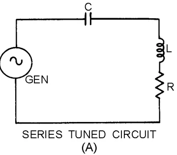
Examine figure 1-1. Notice that a basic tuned circuit consists of a coil and a capacitor, connected either in series, view (A), or in parallel, view (B). The resistance (R) in the circuit is usually limited to the inherent resistance of the components (particularly the resistance of the coil). For our purposes we are going to disregard this small resistance in future diagrams and explanations.
[image:14.612.218.398.233.390.2]Figure 1-1A.—Basic tuned circuits. SERIES TUNED CIRCUIT
Figure 1-1B.—Basic tuned circuits. PARALLEL TUNED CIRCUIT
You have already learned how a coil and a capacitor in an a.c. circuit perform. This action will be the basis of the following discussion about tuned circuits.
You can assume, if you are going to be involved in electricity or electronics, that you will need to have a good working knowledge of tuned circuits and how they are used in electronic and electrical circuits.
REVIEW OF SERIES/PARALLEL A.C. CIRCUITS
First we will review the effects of frequency on a circuit which contains resistance, inductance, and capacitance. This review recaps what you previously learned in the Inductive and Capacitive Reactance chapter in module 2 of the NEETS.
FREQUENCY EFFECTS ON RLC CIRCUITS
Perhaps the most often used control of a radio or television set is the station or channel selector. Of course, the volume, tone, and picture quality controls are adjusted to suit the individual's taste, but very often they are not adjusted when the station is changed. What goes on behind this station selecting? In this chapter, you will learn the basic principles that account for the ability of circuits to "tune" to the desired station.
Effect of Frequency on Inductive Reactance
In an a.c. circuit, an inductor produces inductive reactance which causes the current to lag the voltage by 90 degrees. Because the inductor "reacts" to a changing current, it is known as a reactive component. The opposition that an inductor presents to a.c. is called inductive reactance (X L). This
opposition is caused by the inductor "reacting" to the changing current of the a.c. source. Both the inductance and the frequency determine the magnitude of this reactance. This relationship is stated by the formula:
As shown in the equation, any increase in frequency, or "f," will cause a corresponding increase of inductive reactance, or "XL." Therefore, the INDUCTIVE REACTANCE VARIES DIRECTLY WITH
THE FREQUENCY. As you can see, the higher the frequency, the greater the inductive reactance; the lower the frequency, the less the inductive reactance for a given inductor. This relationship is illustrated in figure 1-2. Increasing values of XL are plotted in terms of increasing frequency. Starting at the lower left
Figure 1-2.—Effect of frequency on inductive reactance.
Effect of Frequency on Capacitive Reactance
In an a.c. circuit, a capacitor produces a reactance which causes the current to lead the voltage by 90 degrees. Because the capacitor "reacts" to a changing voltage, it is known as a reactive component. The opposition a capacitor presents to a.c. is called capacitive reactance (XC). The opposition is caused by the
capacitor "reacting" to the changing voltage of the a.c. source. The formula for capacitive reactance is:
In contrast to the inductive reactance, this equation indicates that the CAPACITIVE REACTANCE VARIES INVERSELY WITH THE FREQUENCY. When f = 0, XC is infinite (∞) and decreases as
frequency increases. That is, the lower the frequency, the greater the capacitive reactance; the higher the frequency, the less the reactance for a given capacitor.
Figure 1-3.—Effect of frequency on capacitive reactance.
Effect of Frequency on Resistance
In the expression for inductive reactance, XL = 2πfL, and in the expression for capacitive reactance,
both contain "f" (frequency). Any change of frequency changes the reactance of the circuit components as already explained. So far, nothing has been said about the effect of frequency on resistance. In an Ohm's law relationship, such as R = E/I no "f" is involved. Thus, for all practical purposes, a change of
frequency does not affect the resistance of the circuit. If a 60-hertz a.c. voltage causes 20 milliamperes of current in a resistive circuit, then the same voltage at 2000 hertz, for example, would still cause 20 milliamperes to flow.
NOTE: Remember that the total opposition to a.c. is called impedance (Z). Impedance is the combination of inductive reactance (XL), capacitive reactance (XC), and resistance (R). When dealing
with a.c. circuits, the impedance is the factor with which you will ultimately be concerned. But, as you have just been shown, the resistance (R) is not affected by frequency. Therefore, the remainder of the discussion of a.c. circuits will only be concerned with the reactance of inductors and capacitors and will ignore resistance.
A.c. Circuits Containing Both Inductive and Capacitive Reactances
A.c. circuits that contain both an inductor and a capacitor have interesting characteristics because of the opposing effects of L and C. X L and XC may be treated as reactors which are 180 degrees out of
X = XL− XC
Suppose an a.c. circuit contains an XL of 300 ohms and an XC of 250 ohms. The resultant reactance
is:
X = XL− XC = 300 − 250 = 50 ohms (inductive)
In some cases, the XC may be larger than the X L. If XL = 1200 ohms and X C = 4000 ohms, the
difference is: X = XL − XC = 1200 − 4000 = −2800 ohms (capacitive). The total carries the sign (+ or −) of
the greater number (factor).
Q-1. What is the relationship between frequency and the values of (a) XL, (b) XC, and (c) R?
Q-2. In an a.c. circuit that contains both an inductor and a capacitor, what term is used for the difference between the individual reactances?
RESONANCE
For every combination of L and C, there is only ONE frequency (in both series and parallel circuits) that causes XL to exactly equal XC; this frequency is known as the RESONANT FREQUENCY. When
the resonant frequency is fed to a series or parallel circuit, X L becomes equal to XC, and the circuit is said
to be RESONANT to that frequency. The circuit is now called a RESONANT CIRCUIT; resonant circuits are tuned circuits. The circuit condition wherein XL becomes equal to XC is known as
RESONANCE.
Each LCR circuit responds to resonant frequency differently than it does to any other frequency. Because of this, an LCR circuit has the ability to separate frequencies. For example, suppose the TV or radio station you want to see or hear is broadcasting at the resonant frequency. The LC "tuner" in your set can divide the frequencies, picking out the resonant frequency and rejecting the other frequencies. Thus, the tuner selects the station you want and rejects all other stations. If you decide to select another station, you can change the frequency by tuning the resonant circuit to the desired frequency.
RESONANT FREQUENCY
As stated before, the frequency at which XL equals XC (in a given circuit) is known as the resonant
frequency of that circuit. Based on this, the following formula has been derived to find the exact resonant frequency when the values of circuit components are known:
There are two important points to remember about this formula. First, the resonant frequency found when using the formula will cause the reactances (XL and XC) of the L and C components to be equal.
The symbol for resonant frequency used in this text is f. Different texts and references may use other symbols for resonant frequency, such as fo, Fr, and fR. The symbols for many circuit parameters have
been standardized while others have been left to the discretion of the writer. When you study, apply the rules given by the writer of the text or reference; by doing so, you should have no trouble with
nonstandard symbols and designations.
The resonant frequency formula in this text is:
By substituting the constant .159 for the quantity
the formula can be simplified to the following:
Let's use this formula to figure the resonant frequency (fr). The circuit is shown in the practice tank
The important point here is not the formula nor the mathematics. In fact, you may never have to compute a resonant frequency. The important point is for you to see that any given combination of L and C can be resonant at only one frequency; in this case, 205 kHz.
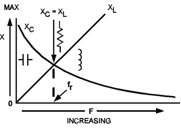
Figure 1-5.—Relationship between XL and XC as frequency increases.
First, note that fr, (the resonant frequency) is that frequency (or point) where the two curves cross. At
this point, and ONLY this point, XL equals XC. Therefore, the frequency indicated by fr is the one and
only frequency of resonance. Note the resistance symbol which indicates that at resonance all reactance is cancelled and the circuit impedance is effectively purely resistive. Remember, a.c. circuits that are resistive have no phase shift between voltage and current. Therefore, at resonance, phase shift is cancelled. The phase angle is effectively zero.
Second, look at the area of the curves to the left of fr. This area shows the relative reactances of the
circuit at frequencies BELOW resonance. To these LOWER frequencies, XC will always be greater than
XL. There will always be some capacitive reactance left in the circuit after all inductive reactance has
been cancelled. Because the impedance has a reactive component, there will be a phase shift. We can also state that below fr the circuit will appear capacitive.
Lastly, look at the area of the curves to the right of f. This area shows the relative reactances of the circuit at frequencies ABOVE resonance. To these HIGHER frequencies, XL will always be greater than
XC. There will always be some inductive reactance left in the circuit after all capacitive reactance has
been cancelled. The inductor symbol shows that to these higher frequencies, the circuit will always appear to have some inductance. Because of this, there will be a phase shift.
RESONANT CIRCUITS
Resonant circuits may be designed as series resonant or parallel resonant. Each has the ability to discriminate between its resonant frequency and all other frequencies. How this is accomplished by both series- and parallel-LC circuits is the subject of the next section.
THE IDEAL SERIES-RESONANT CIRCUIT
The ideal series-resonant circuit contains no resistance; it consists of only inductance and capacitance in series with each other and with the source voltage. In this respect, it has the same
characteristics of the series circuits you have studied previously. Remember that current is the same in all parts of a series circuit because there is only one path for current.
Each LC circuit responds differently to different input frequencies. In the following paragraphs, we will analyze what happens internally in a series-LC circuit when frequencies at resonance, below resonance, and above resonance are applied. The L and C values in the circuit are those used in the problem just studied under resonant-frequency. The frequencies applied are the three inputs from figure 1-6. Note that the resonant frequency of each of these components is 205 kHz, as figured in the problem.
Figure 1-6.—Output of the resonant circuit.
How the Ideal Series-LC Circuit Responds to the Resonant Frequency (205 kHz)
Note: You are given the values of XL, X C, and fr but you can apply the formulas to figure them. The
values given are rounded off to make it easier to analyze the circuit.
First, note that XL and XC are equal. This shows that the circuit is resonant to the applied frequency
of 205 kHz. XL and XC are opposite in effect; therefore, they subtract to zero. (2580 ohms − 2580 ohms =
Now, apply Ohm's law for a.c. circuits:
Don't be confused by this high value of current. Our perfect, but impossible, circuit has no
opposition to current. Therefore, current flow will be extremely high. The important points here are that AT RESONANCE, impedance is VERY LOW, and the resulting current will be comparatively HIGH.
If we apply Ohm's law to the individual reactances, we can figure relative values of voltage across each reactance.
These are reactive voltages that you have studied previously. The voltage across each reactance will be comparatively high. A comparatively high current times 2580 ohms yields a high voltage. At any given instant, this voltage will be of opposite polarity because the reactances are opposite in effect. EL + EC =
zero volts
WARNING
THE INDIVIDUAL VOLTAGES MAY REACH QUITE HIGH VALUES. ALTHOUGH LITTLE POWER IS PRESENT, THE VOLTAGE IS REAL AND CARE SHOULD BE TAKEN IN WORKING WITH IT.
Let's summarize our findings so far. In a series-LC circuit with a resonant-frequency voltage applied, the following conditions exist:
• XL and XC are equal and subtract to zero.
• Resultant reactance is zero ohms.
• Impedance (Z) is reduced to a MINIMUM value.
• With minimum Z, current is MAXIMUM for a given voltage.
How the Ideal Series-LC Circuit Respond to a Frequency Below Resonance (100 kHz)
Given:
First, note that XL and XC are no longer equal. XC is larger than it was at resonance; XL is smaller. By
applying the formulas you have learned, you know that a lower frequency produces a higher capacitive reactance and a lower inductive reactance. The reactances subtract but do not cancel (X L − XC = 1260 −
5300 = 4040 ohms (capacitive)). At an input frequency of 100 kHz, the circuit (still resonant to 205 kHz) has a net reactance of 4040 ohms. In our theoretically perfect circuit, the total opposition (Z) is equal to X, or 4040 ohms.
As before, let's apply Ohm's law to the new conditions.
In summary, in a series-LC circuit with a source voltage that is below the resonant frequency (100 kHz in the example), the resultant reactance (X), and therefore impedance, is higher than at resonance. In addition current is lower, and the voltage drops across the reactances are lower. All of the above follow in sequence due to the fact that XC is greater than XL at any frequency lower than the resonant frequency.
How the Ideal Series-LC Circuit Responds to a Frequency Above Resonance (300 kHz)
Given:
Again, XL and XC are not equal. This time, XL is larger than XC. (If you don't know why, apply the
formulas and review the past several pages.) The resultant reactance is 2000 ohms (XL − X C = 3770 −
1770 = 2000 ohms.) Therefore, the resultant reactance (X), or the impedance of our perfect circuit at 300 kHz, is 2000 ohms.
By applying Ohm's law as before:
In summary, in a series-LC circuit with a source voltage that is above the resonant frequency (300 kHz in this example), impedance is higher than at resonance, current is lower, and the voltage drops across the reactances are lower. All of the above follow in sequence from the fact that X L is greater than
XC at any frequency higher than the resonant frequency.
Summary of the Response of the Ideal Series-LC Circuit to Frequencies Above, Below, and at Resonance
The ideal series-resonant circuit has zero impedance. The impedance increases for frequencies higher and lower than the resonant frequency. The impedance characteristic of the ideal series-resonant circuit results because resultant reactance is zero ohms at resonance and ONLY at resonance. All other frequencies provide a resultant reactance greater than zero.
How the Typical Series-LC Circuit Differs From the Ideal
As you learned much earlier in this series, resistance is always present in practical electrical circuits; it is impossible to eliminate. A typical series-LC circuit, then, has R as well as L and C.
If our perfect (ideal) circuit has zero resistance, and a typical circuit has "some" resistance, then a circuit with a very small resistance is closer to being perfect than one that has a large resistance. Let's list what happens in a series-resonant circuit because resistance is present. This is not new to you - just a review of what you have learned previously.
In a series-resonant circuit that is basically L and C, but that contains "some" R, the following statements are true:
• XL, XC, and R components are all present and can be shown on a vector diagram, each at right
angles with the resistance vector (baseline).
• At resonance, the resultant reactance is zero ohms. Thus, at resonance, The circuit impedance equals only the resistance (R). The circuit impedance can never be less than R because the original resistance will always be present in the circuit.
• At resonance, a practical series-RLC circuit ALWAYS has MINIMUM impedance. The actual value of impedance is that of the resistance present in the circuit (Z = R).
Figure 1-7.—Curves of impedance and current in an RLC series resonant circuit.
Note that the impedance curve does not reach zero at its minimum point. The vectors above and below resonance show that the phase shift of the circuit at these frequencies is less than 90 degrees because of the resistance.
The horizontal width of the curve is a measure of how well the circuit will pick out (discriminate) the one desired frequency. The width is called BANDWIDTH, and the ability to discriminate between frequencies is known as SELECTIVITY. Both of these characteristics are affected by resistance. Lower resistance allows narrower bandwidth, which is the same as saying the circuit has better selectivity. Resistance, then, is an unwanted quantity that cannot be eliminated but can be kept to a minimum by the circuit designers.
More on bandwidth, selectivity, and measuring the effects of resistance in resonant circuits will follow the discussion of parallel resonance.
Q-3. State the formula for resonant frequency.
How the Parallel-LC Circuit Stores Energy
A parallel-LC circuit is often called a TANK CIRCUIT because it can store energy much as a tank stores liquid. It has the ability to take energy fed to it from a power source, store this energy alternately in the inductor and capacitor, and produce an output which is a continuous a.c. wave. You can understand how this is accomplished by carefully studying the sequence of events shown in figure 1-8. You must thoroughly understand the capacitor and inductor action in this figure before you proceed further in the study of parallel-resonant circuits.
In each view of figure 1-8, the waveform is of the charging and discharging CAPACITOR
VOLTAGE. In view (A), the switch has been moved to position C. The d.c. voltage is applied across the capacitor, and the capacitor charges to the potential of the battery.
Figure 1-8A.—Capacitor and inductor action in a tank circuit.
In view (B), moving the switch to the right completes the circuit from the capacitor to the inductor and places the inductor in series with the capacitor. This furnishes a path for the excess electrons on the upper plate of the capacitor to flow to the lower plate, and thus starts neutralizing the capacitor charge. As these electrons flow through the coil, a magnetic field is built up around the coil. The energy which was first stored by the electrostatic field of the capacitor is now stored in the electromagnetic field of the inductor.
View (C) shows the capacitor discharged and a maximum magnetic field around the coil. The energy originally stored in the capacitor is now stored entirely in the magnetic field of the coil.
Figure 1-8C.—Capacitor and inductor action in a tank circuit.
Since the capacitor is now completely discharged, the magnetic field surrounding the coil starts to collapse. This induces a voltage in the coil which causes the current to continue flowing in the same direction and charges the capacitor again. This time the capacitor charges to the opposite polarity, view (D).
Figure 1-8D.—Capacitor and inductor action in a tank circuit.
Figure 1-8E.—Capacitor and inductor action in a tank circuit.
In view (F), the capacitor now discharges back through the coil. This discharge current causes the magnetic field to build up again around the coil.
Figure 1-8F.—Capacitor and inductor action in a tank circuit.
In view (G), the capacitor is completely discharged. The magnetic field is again at maximum.
In view (H), with the capacitor completely discharged, the magnetic field again starts collapsing. The induced voltage from the coil maintains current flowing toward the upper plate of the capacitor.
Figure 1-8H.—Capacitor and inductor action in a tank circuit.
In view (I), by the time the magnetic field has completely collapsed, the capacitor is again charged with the same polarity as it had in view (A). The energy is again stored in the capacitor, and the cycle is ready to start again.
Figure 1-8I.—Capacitor and inductor action in a tank circuit.
The number of times per second that these events in figure 1-8 take place is called NATURAL FREQUENCY or RESONANT FREQUENCY of the circuit. Such a circuit is said to oscillate at its resonant frequency.
It might seem that these oscillations could go on forever. You know better, however, if you apply what you have already learned about electric circuits.
This circuit, as all others, has some resistance. Even the relatively small resistance of the coil and the connecting wires cause energy to be dissipated in the form of heat (I2R loss). The heat loss in the circuit
Figure 1-9.—Damped wave.
If it were possible to have a circuit with absolutely no resistance, there would be no heat loss, and the oscillations would tend to continue indefinitely. You have already learned that tuned circuits are designed to have very little resistance. Reducing I2R losses is still another reason for having low resistance.
A "perfect" tuned circuit would produce the continuous sine wave shown in figure 1-10. Its frequency would be that of the circuit.
Figure 1-10.—Sine wave-resonant frequency.
Because we don't have perfection, another way of causing a circuit to oscillate indefinitely would be to apply a continuous a.c. or pulsing source to the circuit. If the source is at the resonant frequency of the circuit, the circuit will oscillate as long as the source is applied.
The reasons why the circuit in figure 1-8 oscillates at the resonant frequency have to do with the characteristics of resonant circuits. The discussion of parallel resonance will not be as detailed as that for series resonance because the idea of resonance is the same for both circuits. Certain characteristics differ as a result of L and C being in parallel rather than in series. These differences will be emphasized.
Q-7. When the capacitor is completely discharged, where is the energy of the tank circuit stored? Q-8. When the magnetic field of the inductor is completely collapsed, where is the energy of the tank
circuit stored?
PARALLEL RESONANCE
Much of what you have learned about resonance and series-LC circuits can be applied directly to parallel-LC circuits. The purpose of the two circuits is the same — to select a specific frequency and reject all others. XL still equals XC at resonance. Because the inductor and capacitor are in parallel,
frequency selection to be accomplished in a different manner. It gives the circuit different characteristics. The first of these characteristics is the ability to store energy.
The Characteristics of a Typical Parallel-Resonant Circuit
Look at figure 1-11. In this circuit, as in other parallel circuits, the voltage is the same across the inductor and capacitor. The currents through the components vary inversely with their reactances in accordance with Ohm's law. The total current drawn by the circuit is the vector sum of the two individual component currents. Finally, these two currents, IL and IC, are 180 degrees out of phase because the
effects of L and C are opposite. There is not a single fact new to you in the above. It is all based on what you have learned previously about parallel a.c. circuits that contain L and C.
Figure 1-11.—Curves of impedance and current in an RLC parallel-resonant circuit.
Now, at resonance, XL is still equal to X C. Therefore, IL must equal IC. Remember, the voltage is the
By now you know that we have just ignored our old friend resistance from previous discussions. In an actual circuit, at resonance, the currents will not quite counteract each other because each component will have different resistance. This resistance is kept extremely low, but it is still there. The result is that a relatively small current flows from the source at resonance instead of zero current. Therefore, a basic characteristic of a practical parallel-LC circuit is that, at resonance, the circuit has MAXIMUM
impedance which results in MINIMUM current from the source. This current is often called line current. This is shown by the peak of the waveform for impedance and the valley for the line current, both occurring at fr the frequency of resonance in figure 1-11.
There is little difference between the circuit pulsed by the battery in figure 1-8 that oscillated at its resonant (or natural) frequency, and the circuit we have just discussed. The equal and opposite currents in the two components are the same as the currents that charged and discharged the capacitor through the coil.
For a given source voltage, the current oscillating between the reactive parts will be stronger at the resonant frequency of the circuit than at any other frequency. At frequencies below resonance, capacitive current will decrease; above the resonant frequency, inductive current will decrease. Therefore, the oscillating current (or circulating current, as it is sometimes called), being the lesser of the two reactive currents, will be maximum at resonance.
If you remember, the basic resonant circuit produced a "damped" wave. A steady amplitude wave was produced by giving the circuit energy that would keep it going. To do this, the energy had to be at the same frequency as the resonant frequency of the circuit.
So, if the resonant frequency is "timed" right, then all other frequencies are "out of time" and produce waves that tend to buck each other. Such frequencies cannot produce strong oscillating currents.
In our typical parallel-resonant (LC) circuit, the line current is minimum (because the impedance is maximum). At the same time, the internal oscillating current in the tank is maximum. Oscillating current may be several hundred times as great as line current at resonance.
In any case, this circuit reacts differently to the resonant frequency than it does to all other frequencies. This makes it an effective frequency selector.
Summary of Resonance
Both series- and parallel-LC circuits discriminate between the resonant frequency and all other frequencies by balancing an inductive reactance against an equal capacitive reactance.
In series, these reactances create a very low impedance. In parallel, they create a very high impedance. These characteristics govern how and where designers use resonant circuits. A low-impedance requirement would require a series-resonant circuit. A high-low-impedance requirement would require the designer to use a parallel-resonant circuit.
Tuning a Band of Frequencies
Our resonant circuits so far have been tuned to a single frequency - the resonant frequency. This is fine if only one frequency is required. However, there are hundreds of stations on many different frequencies.
What is a practical solution to this problem? The answer is simple. Make either the capacitor or the inductor variable. Remember, changing either L or C changes the resonant frequency.
Now you know what has been happening all of these years when you "pushed" the button or "turned" the dial. You have been changing the L or C in the tuned circuits by the amount necessary to adjust the tuner to resonate at the desired frequency. No matter how complex a unit, if it has LC tuners, the tuners obey these basic laws.
Q-9. What is the term for the number of times per second that tank circuit energy is either stored in the inductor or capacitor?
Q-10. In a parallel-resonant circuit, what is the relationship between impedance and current? Q-11. When is line current minimum in a parallel-LC circuit?
RESONANT CIRCUITS AS FILTER CIRCUITS
The principle of series- or parallel-resonant circuits have many applications in radio, television, communications, and the various other electronic fields throughout the Navy. As you have seen, by making the capacitance or inductance variable, the frequency at which a circuit will resonate can be controlled.
In addition to station selecting or tuning, resonant circuits can separate currents of certain frequencies from those of other frequencies.
Circuits in which resonant circuits are used to do this are called FILTER CIRCUITS.
If we can select the proper values of resistors, inductors, or capacitors, a FILTER NETWORK, or "frequency selector," can be produced which offers little opposition to one frequency, while BLOCKING or ATTENUATING other frequencies. A filter network can also be designed that will "pass" a band of frequencies and "reject" all other frequencies.
Most electronic circuits require the use of filters in one form or another. You have already studied several in modules 6, 7, and 8 of the NEETS.
One example of a filter being applied is in a rectifier circuit. As you know, an alternating voltage is changed by the rectifier to a direct current. However, the d.c. voltage is not pure; it is still pulsating and fluctuating. In other words, the signal still has an a.c. component in addition to the d.c. voltage. By feeding the signal through simple filter networks, the a.c. component is reduced. The remaining d.c. is as pure as the designers require.
Bypass capacitors, which you have already studied, are part of filter networks that, in effect, bypass, or shunt, unwanted a.c. components to ground.
THE IDEA OF "Q"
and useful to designers. Technicians should have some knowledge of the factor because it affects so many things. The factor is known as Q. Some say it stands for quality (or merit). The higher the Q, the better the circuit; the lower the losses (I2R), the closer the circuit is to being perfect.
Having studied the first part of this chapter, you should not be surprised to learn that resistance (R) has a great effect on this figure of merit or quality.
Q Is a Ratio
Q is really very simple to understand if you think back to the tuned-circuit principles just covered. Inductance and capacitance are in all tuners. Resistance is an impurity that causes losses. Therefore, components that provide the reactance with a minimum of resistance are "purer" (more perfect) than those with higher resistance. The actual measure of this purity, merit, or quality must include the two basic quantities, X and R.
The ratio
does the job for us. Let's take a look at it and see just why it measures quality.
First, if a perfect circuit has zero resistance, then our ratio should give a very high value of Q to reflect the high quality of the circuit. Does it?
Assume any value for X and a zero value for R. Then:
Remember, any value divided by zero equals infinity. Thus, our ratio is infinitely high for a theoretically perfect circuit.
With components of higher resistance, the Q is reduced. Dividing by a larger number always yields a smaller quantity. Thus, lower quality components produce a lower Q. Q, then, is a direct and accurate measure of the quality of an LC circuit.
Q is just a ratio. It is always just a number — no units. The higher the number, the "better" the circuit. Later as you get into more practical circuits, you may find that low Q may be desirable to provide certain characteristics. For now, consider that higher is better.
Because capacitors have much, much less resistance in them than inductors, the Q of a circuit is very often expressed as the Q of the coil or:
The Q of a Coil
Q is a feature that is designed into a coil. When the coil is used within the frequency range for which it is designed, Q is relatively constant. In this sense, it is a physical characteristic.
Inductance is a result of the physical makeup of a coil - number of turns, core, type of winding, etc. Inductance governs reactance at a given frequency. Resistance is inherent in the length, size, and material of the wire. Therefore, the Q of a coil is mostly dependent on physical characteristics.
Values of Q that are in the hundreds are very practical and often found in typical equipment.
Application of Q
For the most part, Q is the concern of designers, not technicians. Therefore, the chances of you having to figure the Q of a coil are remote. However, it is important for you to know some circuit relationships that are affected by Q.
Q Relationships in Series Circuits
Q can be used to determine the "gain" of series-resonant circuits. Gain refers to the fact that at resonance, the voltage drop across the reactances are greater than the applied voltage. Remember, when we applied Ohm's law in a series-resonant circuit, it gave us the following characteristics:
• Low impedance, high current.
• High current; high voltage across the comparatively high reactances.
This high voltage is usable where little power is required, such as in driving the grid of a vacuum tube or the gate of a field effect transistor (F.E.T.). The gain of a properly designed series-resonant circuit may be as great or greater than the amplification within the amplifier itself. The gain is a function of Q, as shown in the following example:
If the Q of the coil were 100, then the gain would be 100; that is, the voltage of the coil would be 100 times that of the input voltage to the series circuit.
Table 1-1.—Major Characteristics of Series RLC Circuits at Resonance
Q Relationships in a Parallel-Resonant Circuit
Given:
Again, if the Q were 100, the circulating current would be 100 times the value of the line current. This may help explain why some of the wire sizes are very large in high-power amplifying circuits.
The impedance curve of a parallel-resonant circuit is also affected by the Q of the circuit in a manner similar to the current curve of a series circuit. The Q of the circuit determines how much the impedance is increased across the parallel-LC circuit. (Z = Q × XL)
Table 1-2.—Major Characteristics of Parallel RLC Circuits at
Resonance
Summary of Q
The ratio that is called Q is a measure of the quality of resonant circuits and circuit components. Basically, the value of Q is an inverse function of electrical power dissipated through circuit resistance. Q is the ratio of the power stored in the reactive components to the power dissipated in the resistance. That is, high power loss is low Q; low power loss is high Q.
BANDWIDTH
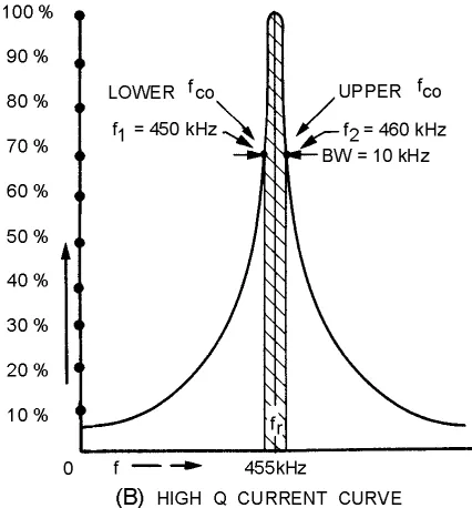
[image:41.612.195.408.401.630.2]If circuit Q is low, the gain of the circuit at resonance is relatively small. The circuit does not discriminate sharply (reject the unwanted frequencies) between the resonant frequency and the frequencies on either side of resonance, as shown by the curve in figure 1-12, view (A). The range of frequencies included between the two frequencies (426.4 kHz and 483.6 kHz in this example) at which the current drops to 70 percent of its maximum value at resonance is called the BANDWIDTH of the circuit.
Figure 1-12A.—Bandwidth for high- and low-Q series circuit. LOW Q CURRENT CURVE.
Figure 1-12B.—Bandwidth for high- and low-Q series circuit. HIGH Q CURRENT CURVE.
below the resonant frequency point. The two points are designated upper frequency cutoff (fco) and lower
frequency cutoff (fco) or simply f1 and f2. The range of frequencies between these two points comprises
the bandwidth. Views (A) and (B) of figure 1-12 illustrate the bandwidths for low- and high-Q resonant circuits. The bandwidth may be determined by use of the following formulas:
For example, by applying the formula we can determine the bandwidth for the curve shown in figure 1-12, view (A).
If the Q of the circuit represented by the curve in figure 1-12, view (B), is 45.5, what would be the bandwidth?
The Q of the circuit can be determined by transposing the formula for bandwidth to:
To find the Q of the circuit using the information found in the last example problem:
Q-12. What is the relationship of the coil to the resistance of a circuit with high "Q"?
Q-13. What is the band of frequencies called that is included between the two points at which current falls to 70 percent of its maximum value in a resonant circuit?
FILTERS
In many practical applications of complex circuits, various combinations of direct, low-frequency, audio-frequency, and radio-frequency currents may exist. It is frequently necessary to have a means for separating these component currents at any desired point. An electrical device for accomplishing this separation is called a FILTER.
The use of resistance by itself in filter circuits does not provide any filtering action, because it opposes the flow of any current regardless of its frequency. What it does, when connected in series or parallel with an inductor or capacitor, is to decrease the "sharpness," or selectivity, of the filter. Hence, in some particular application, resistance might be used in conjunction with inductance or capacitance to provide filtering action over a wider band of frequencies.
Filter circuits may be divided into four general types: LOW-PASS, HIGH-PASS, BANDPASS, AND BAND-REJECT filters.
Electronic circuits often have currents of different frequencies. The reason is that a source produces current with the same frequency as the applied voltage. As an example, the a.c. signal input to an audio amplifier can have high- and low-audio frequencies; the input to an rf amplifier can have a wide range of radio frequencies.
In such applications where the current has different frequency components, it is usually necessary for the filter either to accept or reject one frequency or a group of frequencies. The electronic filter that can pass on the higher-frequency components to a load or to the next circuit is known as a HIGH-PASS filter. A LOW-PASS filter can be used to pass on lower-frequency components.
Before discussing filters further, we will review and apply some basic principles of the frequency-response characteristics of the capacitor and the inductor. Recall the basic formula for capacitive reactance and inductive reactance:
Assume any given value of L and C. If we increase the applied frequency, XC decreases and XL
increases. If we increase the frequency enough, the capacitor acts as a short and the inductor acts as an open. Of course, the opposite is also true. Decreasing frequency causes XC to increase and XL to decrease.
Here again, if we make a large enough change, XC acts as an open and XL acts as a short. Figure 1-13
gives a pictorial representation of these two basic components and how they respond to low and high frequencies.
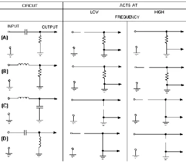
If we apply these same principles to simple circuits, such as the ones in figure 1-14, they affect input signals as shown. For example, in view (A) of the figure, a low frequency is blocked by the capacitor which acts as an open and at a high frequency the capacitor acts as a short. By studying the figure, it is easy to see how the various components will react in different configurations with a change in frequency.
Figure 1-14.—Reaction to circuit by change in frequency.
As mentioned before, high-pass and low-pass filters pass the specific frequencies for which circuits are designed.
There can be a great deal of confusion when talking about high-pass, low-pass, discrimination, attenuation, and frequency cutoff, unless the terms are clearly understood. Since these terms are used widely throughout electronics texts and references, you should have a clear understanding before proceeding further.
• DISCRIMINATION. The ability of the filter circuit to distinguish between high and low frequencies and to eliminate or reject the unwanted frequencies.
• ATTENUATION. The ability of the filter circuit to reduce the amplitude of the unwanted frequencies below the level of the desired output frequency.
• FREQUENCY CUTOFF (fco). The frequency at which the filter circuit changes from the point of
rejecting the unwanted frequencies to the point of passing the desired frequency; OR the point at which the filter circuit changes from the point of passing the desired frequency to the point of rejecting the undesired frequencies.
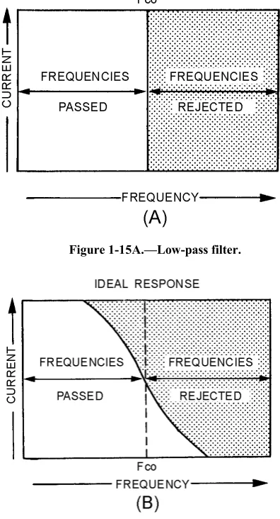
LOW-PASS FILTER
A low-pass filter passes all currents having a frequency below a specified frequency, while opposing all currents having a frequency above this specified frequency. This action is illustrated in its ideal form in view (A) of figure 1-15. At frequency cutoff, known as fc the current decreases from maximum to zero.
At all frequencies above fc the filter presents infinite opposition and there is no current. However, this
[image:46.612.207.405.333.699.2]sharp division between no opposition and full opposition is impossible to attain. A more practical graph of the current is shown in view (B), where the filter gradually builds up opposition as the cutoff frequency (f) is approached. Notice that the filter cannot completely block current above the cutoff frequency.
Figure 1-15A.—Low-pass filter.
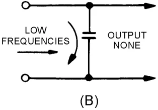
View (A) of figure 1-16 shows the electrical construction of a low-pass filter with an inductor inserted in series with one side of a line carrying both low and high frequencies. The opposition offered by the reactance will be small at the lower frequencies and great at the higher frequencies. In order to divert the undesired high frequencies back to the source, a capacitor must be added across the line to bypass the higher frequencies around the load, as shown in view (B).
[image:47.612.233.382.146.263.2]Figure 1-16A.—Components of a simple low-pass filter.
Figure 1-16B.—Components of a simple low-pass filter.
Figure 1-16C.—Components of a simple low-pass filter.
[image:47.612.228.385.316.426.2]the least amount of opposition is offered to the high frequencies by the capacitor, and most of the high-frequency energy returns to the source through the capacitor.
HIGH-PASS FILTER
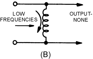
A high-pass filter circuit passes all currents having a frequency higher than a specified frequency, while opposing all currents having a frequency lower than its specified frequency. This is illustrated in figure 1-17. A capacitor that is used in series with the source of both high and low frequencies, as shown in view (A) of figure 1-18, will respond differently to high-frequency, low-frequency, and direct currents. It will offer little opposition to the passage of high-frequency currents, great opposition to the passage of low-frequency currents, and completely block direct currents. The value of the capacitor must be chosen so that it allows the passage of all currents having frequencies above the desired value, and opposes those having frequencies below the desired value. Then, in order to shunt the undesired low-frequency currents back to the source, an inductor is used, as shown in view (B). This inductor must have a value that will allow it to pass currents having frequencies below the frequency cutoff point, and reject currents having frequencies above the frequency cutoff point, thus forcing them to pass through the capacitor. By combining inductance and capacitance, as shown in view (C), you obtain the simplest type of high-pass filter. At point P most of the high-frequency energy is passed on to the load by the capacitor, and most of the low-frequency energy is shunted back to the source through the inductor.
Figure 1-17.—High-pass filter response curve.
Figure 1-18B.—Components of a simple high-pass filter.
Figure 1-18C.—Components of a simple high-pass filter.
RESONANT CIRCUITS AS FILTERS
Resonant circuits can be made to serve as filters in a manner similar to the action of individual capacitors and inductors. As you know, the series-LC circuit offers minimum opposition to currents that have frequencies at or near the resonant frequency, and maximum opposition to currents of all other frequencies.
You also know that a parallel-LC circuit offers a very high impedance to currents that have frequencies at or near the resonant frequency, and a relatively low impedance to currents of all other frequencies.
If you use these two basic concepts, the BANDPASS and BAND-REJECT filters can be constructed. The bandpass filter and the band-reject filter are two common types of filters that use resonant circuits.
Bandpass Filter
A bandpass filter passes a narrow band of frequencies through a circuit and attenuates all other frequencies that are higher or lower than the desired band of frequencies. This is shown in figure 1-19 where the greatest current exists at the center frequency (fr). Frequencies below resonance (f1) and
Figure 1-19.—Bandpass filter response curve.
In the circuit of figure 1-20, view (A), the series-LC circuit replaces the inductor of figure 1-16, view (A), and acts as a BANDPASS filter. It passes currents having frequencies at or near its resonant
frequency, and opposes the passage of all currents having frequencies outside this band.
Figure 1-20A.—Components of a simple bandpass filter.
Thus, in the circuit of figure 20, view (B), the parallel-LC circuit replaces the capacitor of figure 1-16, view (B). If this circuit is tuned to the same frequency as the series-LC circuit, it will provide a path for all currents having frequencies outside the limits of the frequency band passed by the series-resonant circuit. The simplest type of bandpass filter is formed by connecting the two LC circuits as shown in figure 1-20, view (C). The upper and lower frequency limits of the filter action are filter cutoff points.
Figure 1-20C.—Components of a simple bandpass filter.
Band-Reject Filter
A band-reject filter circuit is used to block the passage of current for a narrow band of frequencies, while allowing current to flow at all frequencies above or below this band. This type of filter is also known as a BAND-SUPPRESSION or BAND-STOP filter. The way it responds is shown by the response curve of figure 1-21. Since the purpose of the band-reject filter is directly opposite to that of a bandpass filter, the relative positions of the resonant circuits in the filter are interchanged. The parallel-LC circuit shown in figure 1-22, view (A), replaces the capacitor of figure 1-18, view (A). It acts as a band-reject filter, blocking the passage of currents having frequencies at or near resonant frequency and passing all currents having frequencies outside this band. The series-LC circuit shown in figure 1-22, view (B), replaces the inductor of figure 1-18, view (B). If this series circuit is tuned, to the same frequency as the parallel circuit, it acts as a bypass for the band of rejected frequencies. Then, the simplest type of band-reject filter is obtained by connecting the two circuits as shown in figure 1-22, view (C).
Figure 1-22A.—Components of a simple band-reject filter.
Figure 1-22B.—Components of a simple band-reject filter.
Figure 1-22C.—Components of a simple band-reject filter.
Q-14. What is the device called that will separate alternating current from direct current, or that will separate alternating current of one frequency from other alternating currents of different frequencies?
[image:52.612.216.391.270.410.2]Q-16. What is the filter called in which the low frequencies do not produce a useful voltage?
Q-17. What is the filter called that passes low frequencies but rejects or attenuates high frequencies? Q-18. How does a capacitor and an inductor react to (a) low frequency and (b) high frequency? Q-19. What term is used to describe the frequency at which the filter circuit changes from the point of
rejecting the unwanted frequencies to the point of passing the desired frequencies?
Q-20. What type filter is used to allow a narrow band of frequencies to pass through a circuit and attenuate all other frequencies above or below the desired band?
Q-21. What type filter is used to block the passage of current for a narrow band of frequencies, while allowing current to flow at all frequencies above or below this band?
MULTISECTION FILTERS
All of the various types of filters we have discussed so far have had only one section. In many cases, the use of such simple filter circuits does not provide sufficiently sharp cutoff points. But by adding a capacitor, an inductor, or a resonant circuit in series or in parallel (depending upon the type of filter action required), the ideal effect is more nearly approached. When such additional units are added to a filter circuit, the form of the resulting circuit will resemble the letter T, or the Greek letter π (pi). They are, therefore, called T- or π-type filters, depending upon which symbol they resemble. Two or more T- or π−type filters may be connected together to produce a still sharper cutoff point.
Figure 1-23, (view A) (view B) and (view C), and figure 1-24, (view A) (view B) and (view C) depict some of the common configurations of the T- and π-type filters. Further discussion about the theory of operation of these circuits is beyond the intended scope of this module. If you are interested in learning more about filters, a good source of information to study is the Electronics Installation and Maintenance Handbook (EIMB), section 4 (Electronics Circuits), NAVSEA 0967-LP-000-0120.
Figure 1-23B.—Formation of a T-type filter.
Figure 1-23C.—Formation of a T-type filter.
Figure 1-24A.—Formation of a ππππ-type filter.
Figure 1-24C.—Formation of a ππππ-type filter.
SAFETY PRECAUTIONS
When working with resonant circuits, or electrical circuits, you must be aware of the potentially high voltages. Look at figure 1-25. With the series circuit at resonance, the total impedance of the circuit is 5 ohms.
Figure 1-25.—Series RLC circuit at resonance.
Remember, the impedance of a series-RLC circuit at resonance depends on the resistive element. At resonance, the impedance (Z) equals the resistance (R). Resistance is minimum and current is maximum. Therefore, the current at resonance is:
The voltage drops around the circuit with 2 amperes of current flow are:
EC = IT× X C
EL = 2 × 20
EL = 40 volts a.c.
ER = IT× R
ER = 2 × 5
ER = 10 volts a.c.
You can see that there is a voltage gain across the reactive components at resonance.
If the frequency was such that XL and X C were equal to 1000 ohms at the resonant frequency, the
reactance voltage across the inductor or capacitor would increase to 2000 volts a.c. with 10 volts a.c. applied. Be aware that potentially high voltage can exist in series-resonant circuits.
SUMMARY
This chapter introduced you to the principles of tuned circuits. The following is a summary of the major subjects of this chapter.
THE EFFECT OF FREQUENCY on an INDUCTOR is such that an increase in frequency will cause an increase in inductive reactance. Remember that XL = 2πfL; therefore, XL varies directly with
frequency.
THE EFFECT OF FREQUENCY on a CAPACITOR is such that an increase in frequency will cause a decrease in capacitive reactance. Remember that
RESULTANT REACTANCE X = (XL − X C) or X = (XC − XL). XL is usually plotted above the
reference line and X C below the reference line. Inductance and capacitance have opposite effects on the
current in respect to the voltage in a.c. circuits. Below resonance, XC is larger than XL, and the series
circuit appears capacitive. Above resonance, XL is larger than XC, and the series circuit appears inductive.
At resonance, XL = XC, and the total impedance of the circuit is resistive.
A RESONANT CIRCUIT is often called a TANK CIRCUIT. It has the ability to take energy fed from a power source, store the energy alternately in the inductor and capacitor, and produce an output which is a continuous a.c. wave. The number of times this set of events occurs per second is called the resonant frequency of the circuit. The actual frequency at which a tank circuit will oscillate is determined by the formula: