Numerical analysis of the embedded abutments of integral bridges
Ming XU
Researcher, Dept. of Civil & Env. Engrg., University of Southampton, UK
Alan G. BLOODWORTH Lecturer, Dept. of Civil & Env. Engrg., University of Southampton, UK
Marcus M. K. LEE
Professor, Dept. of Civil & Env. Engrg., University of Southampton, UK
Summary
A numerical case study is presented, which investigates the performance of embedded integral bridge abutments and the maximum magnitude and distribution of earth pressure within the retained soil. The Three Surface Kinematic Hardening model is adopted in the numerical analysis, which successfully reproduced key features of soil behaviour under small strain cyclic loading. The results show that the earth pressures change in a complicated way, while the largest bending moments in the abutment wall increase with cycles at a decreasing rate, with a final value far less than the one derived from current design standards. A number of factors have been investigated and the influences of the wall flexure and soil stiffness are highlighted. The research results will lead to safe and economic design of such structures.
Keywords: integral bridge, soil-structure interaction, cyclic loading, soil stiffness
1. Introduction
The most common design concept for road and railway bridges traditionally includes the use of some type of joints and bearings at each end, which separate the superstructure from the abutments to accommodate the seasonal relative movement between them. These joints and bearings are prone to be leakage and are affected by de-icing salts and other sources of corrosion, thus requiring regular inspection and maintenance. Because of these costly problems, a concept was developed to physically and structurally connect the superstructure and abutment to create what is referred to as an integral bridge. Integral bridges could eliminate the cost of, and the additional work associated with, the provision of movement joints at the ends of the bridge. It also brings the benefits of reduced maintenance costs and eliminated risk of damage arising from leaky joints. In addition, because the superstructures are structurally integrated with the abutments, the whole bridge is potentially more resistant to horizontal forces, which make it especially suitable for high-speed railway transportation.
However, integral bridges are not free of problems at all. The seasonal change of temperature causes the bridge superstructure to expand and contract. Because of the integral connection between superstructure and the abutments, the abutments are forced to move away from the soil they retain in the winter and into the soil during the summer. This cyclic movement appear to cause the build-up of lateral earth pressures acting on the abutments. There are considerable uncertainties concerning the final magnitude and distribution of such pressures. To reduce such uncertainties and to provide guidance on design, a research programme is being carried out at the University of Southampton, which includes both numerical and experiment work. The research is being continued with high quality triaxial testing of soil samples at small cyclic strains, at stress paths appropriate to the integral bridge problem. In this paper, the results of a numerical case study are presented and discussed.
2. Numerical Case Study
embedded abutment bridge, the dimension of which is shown in Figure 1. The abutment is 12m high and the retained height is 6m. The bridge span is 60m while the concrete wall thickness is 1m.
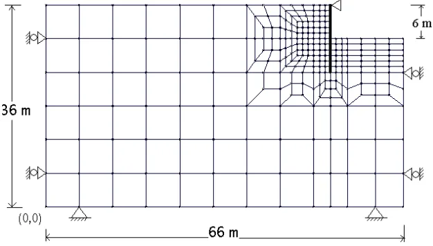
[image:2.595.138.451.248.426.2]Although the stiffness of the bridge deck and the vertical load and the bending moment transferred from the deck can have great influence on the abutment, only the interaction between the soil and the abutment due to seasonal temperature change are considered in this case. To simplify the problem, the bridge deck is modelled as a pin prop at the top of the abutment and the thermal expansion of the bridge deck is represented by a horizontal movement of the pin prop. The geometric modelling and discretization is shown in Figure 2.
Fig. 2 The finite element mesh
Boundaries were located remote from the area influenced by the stress change; the vertical boundaries were restrained in the horizontal direction while the bottom horizontal boundary was completely restrained from movement. Eight-node linear strain quadrilateral elements (LSQ) with full integration were used to model the soil. Three-node linear strain beam elements were adopted to model the wall. The element size was reduced until it had no significant effects on the analysis. The section through the abutment was analysed in plane strain. It should be noticed that a plane strain analysis will tend to overestimate the earth pressure if there is in reality some deformation out of plane.
The soil material was modelled by the Three-Surface Kinematic Hardening (3-SKH) model [2], which has been proven to be able to take account of the effects of the high shear stiffness at very small strain, the effective stress history on stiffness and the changes in stiffness due to cyclic loading. In the analysis, the soil was assumed to be overconsolidated clay, which is common in UK. The model parameters used are shown as below:
Table 1 The parameters for the 3-SKH model
k* λ* ecs M Gec T S ψ
0.005 0.073 1.994 0.89 1964p’0.65 Ro0.2 0.25 0.08 2.5
R0 Overconsolidation ratio.
k* Slope of Swelling line in lnυ-lnp’ space
0 400 800 1200 1600 2000
0 5 10 15 20 25 30
Cycle No.
L
arg
es
t b
en
d
in
g m
om
en
t
(k
N
m
/m
)
λ* Slope of normal compression line in lnυ-lnp’space
ecs Void's ratio of isotropically normally compressed soil when p’=1 M Slope of critical state line
Gec Shear modulus (KN/m2)
T Ratio of extent of stress history surface
S Ratio of extent of yield surface
Ψ Exponent of hardening modulus
Considering that the stress history can greatly influence the soil behaviour, the analysis was divided into several steps to simulate the whole construction process as closely as possible:
Step 1. An overburden was applied to the normally consolidated soil and then removed to simulate the largest overburden history.
Step 2. The abutment was installed in the soil by adding the beam element representing the abutment. Then a surcharging load of 10 kPa was applied to the retained soil surface. Step 3. The soil was excavated to -2.0m and then the prop was installed at the top of the wall. Step 4. The soil was excavated to -6.0 m to the designed bottom level.
Step 5. 30 cycles of the top displacement were applied. For a typical 60 m long concrete deck, the seasonal abutment top movement is about ±10 mm. Considering the long period of each cycle, such that there is enough time for the excessive pore pressure to dissipate, the soil is assumed to behave as drained.
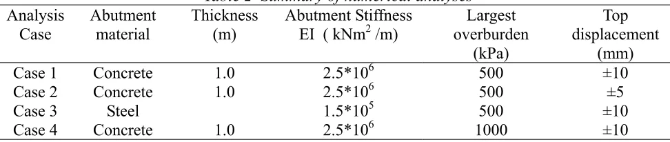
[image:3.595.52.538.414.517.2]To investigate the influence of wall stiffness, the magnitude of cyclic seasonal movement and the extent of overconsolidation, three other cases (Case 2~4) are also studied for comparison. All four cases are summarized in Table 2.
Table 2 Summary of numerical analyses Analysis
Case
Abutment material
Thickness (m)
Abutment Stiffness EI ( kNm2 /m)
Largest overburden
(kPa)
Top displacement
(mm)
Case 1 Concrete 1.0 2.5*106 500 ±10
Case 2 Concrete 1.0 2.5*106 500 ±5
Case 3 Steel 1.5*105 500 ±10
Case 4 Concrete 1.0 2.5*106 1000 ±10
3. Results and Discussion
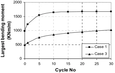
3.1 The result of case 1The increase of peak bending moment with cycles is shown in Figure 3. There is a rapid escalation from the initial value during the first ten cycles, after which the changes were considerably slower and following a decreasing rate. The largest bending moment tends to approach a limit value after 20 cycles, which implies that the soil may reach a resilient state. This tendency has also been seen with the experiment results of England et al. [3] and the ultimate limit case of the
0 500 1000 1500 2000
0 5 10 15 20 25 30
Cycle No La rg es t be nd in g m o m ent (K N m /m ) Case 1 Case 3
The earth pressures (Figure 4) increase in the upper 2/3 of the wall but decrease in the lower part of the wall. The earth pressure in the middle part increases about 20%, but it is still far less than the pressure advised by the UK current design standard BA 42 [5], which is considered in practice to be very conservative. The deformed shape (Figure 5) is mainly dominated by rotation with the largest displacement at the toe, which is mainly because of the large stiffness of the thick concrete wall.
Earth pressure behind the wall (kN/m^2)
Y C oo rdi na te o f t h e w all no des ( m )
30 78 126 174 222 270
24 26 28 30 32 34 36 Initial pressure After excavation 1st cycle 30th cycle Initial pressure After excavation 1st cycle 30th cycle
Fig. 4 The earth pressures behind the abutment in Case 1
Horizontal displacement (m)
Y C oo rdi na te o f t h e w all no des ( m )
0.017 0.042 0.066 0.091 0.115 0.140
[image:4.595.133.460.145.341.2]24 26 28 30 32 34 36 After excavation 1st cycle 30th cycle After excavation 1st cycle 30th cycle
Fig. 5 The deformation shape of the abutment in Case 1
3.2 Influence of abutment stiffness
A flexible sheet steel pile wall with EI=1.5*105 kNm2/m was investigated in Case 3 (Figure 6). The trend of increase of the largest bending moment of the flexible steel pile wall is similar to the rigid concrete wall, but the absolute value is significantly smaller than for the concrete wall, which implies that the wall stiffness can influence the bending moment greatly. The reason could be that the flexure of the sheet pile wall
tends to relieve the high earth pressure at the middle part (Figure 7).
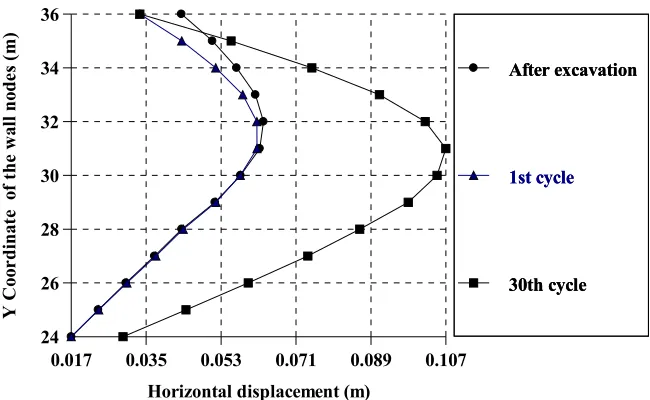
[image:4.595.133.462.370.569.2] [image:4.595.57.254.605.730.2]The deformation of the flexible wall in Case 3 is mainly bending with the largest displacement at the middle of the wall and relatively small displacement at the toe (Figure 8). The deformation shape is significantly different from the concrete abutment (Figure 5).
Earth pressure behind the wall (kN/m^2)
Y C
oo
rdi
na
te
o
f t
h
e
w
all
no
des
(
m
)
33 87 142 196 250 305
24 26 28 30 32 34 36
Initial pressure
After excavation
1st cycle
30th cycle Initial pressure
After excavation
1st cycle
[image:5.595.135.462.114.313.2]30th cycle
Fig. 7 The earth pressures behind the abutment in Case 3
Horizontal displacement (m)
Y Co
or
d
in
at
e
of
t
h
e wa
ll
n
od
es
(
m
)
0.017 0.035 0.053 0.071 0.089 0.107
24 26 28 30 32 34 36
After excavation
1st cycle
30th cycle After excavation
1st cycle
30th cycle
Fig. 8 The wall deformation shape in Case 3
3.3 The influence of top displacement
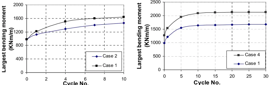
Two top displacements were investigated: ±5mm and ±10mm. The largest bending moment of each case is summarized in Figure 9. As there is little increase after the first 10 cycles, only the first 10 cycles were compared. The peak largest bending moment increases with the top displacement, but the increase of the Case 1 (±10mm) is only 1.4 times larger than the Case 2 (±5mm), demonstrating the non-linear behaviour of the soil-structure interaction.
3.4 The influence of stress history
[image:5.595.137.462.346.546.2]0 400 800 1200 1600 2000
0 2 4 6 8 10
Cycle No.
L
ar
g
e
s
t b
en
di
ng m
o
m
en
t
(KNm
/m
)
Case 2
Case 1
0 500 1000 1500 2000 2500
0 5 10 15 20 25 30
Cycle No.
Lar
g
es
t bend
in
g
m
o
m
ent
(KNm
/m
)
Case 4 Case 1
Fig. 9 The largest bending moment of Cases 1& 2 Fig. 10 The largest bending moment of Cases 1& 4
4. Conclusion
Integral bridges can greatly reduce mantenance costs and are especially suitable for high-speed railway transportation. This paper described a numerical study of an embedded integral abutment. The results show that the earth pressures change in a complicated way, relating to the wall stiffness, the soil stiffness and the magnitude of cyclic seasonal movement. The largest bending moments in the abutment wall increase at a decreasing rate and will reach an maximum value after about twenty cycles, which is far less than the one derived from current design standards. The wall stiffness can greatly influence the soil behaviour behind the abutments, and the adoption of a flexible wall could lead to an economic design.
5. References
[1] Crisp Consortium Limited, Sage Crisp 4.3a Technical Manual, 2002
[2] STALLEBRASS, S.E. and TAYLOR, R.N. Development and evaluation of a constitutive model for the prediction of ground movements in overconsolidated soils. Géotechnique, Vol. 47, No. 2, 1997, pp.235-253.
[3] ENGLAND G.L., TSANG C.M. and BUSH D. Integral Bridges - A Fundamental Approach to the Time Temperature Loading Problem, Thomas Telford, London, 2000, 200pp.
[4] SPRINGMAN, S.M., NORRISH, A. and NG, C.W.W. Cyclic loading of sand behind integral bridge abutments, Transport Research Laboratory Project Report 146, 1996.
[image:6.595.87.516.86.222.2]