Abstract— This paper presents the development of a new approach to visualize gas jet from an automotive fuel injector. This method of visualizing gas jet in water can be used to investigate the gas jet structure, development and interaction with the environment where injection takes place. The fuel injector used is called Spark Plug Fuel Injector (SPFI). SPFI is a low cost conversion device for conversion to compressed natural gas direct injection (CNGDI) in spark ignition engine. The experiment was carried out to measure the gas jet of SPFI by using pure gaseous nitrogen as compressed natural gas substitute for safety proposes. Nitrogen was injected at 40, 50 and 60 bar with different length of SPFI’s fuel path. The images of the gas bubbles which formed at the nozzle of the SPFI for different time after the start of injection (SOI) from a direct fuel injector were captured using a digital camera where exposure times were adjusted accordingly. The fuel injection was synchronized with a flash light using MOSFET-controlled circuit and two pulse generators. Two sets of SPFI with different fuel path length were used. Results showed that the SPFI with shorter fuel path achieved shorter fuel delivery time and less pressure loss. The gas jets of the longer SPFI were 11.70% and 2.5% shorter and narrower than that of gas jet of shorter SPFI. The results also showed that higher injection pressure increased both gas jet length and width of SPFI and the shape of the gas jet were in agreement with the vortex ball model [1] but with different degree of penetration compared to gas jet in air environment. This investigation of gas jet structure must be further elaborated with different water pressure in order to reach governing equations and ultimately correlated to the vortex ball model for a possible low cost gaseous flow visualization technique.
Index Terms—compressed natural gas, flow visualization, gas jet, spark plug fuel injector.
I. INTRODUCTION
In recent times, the accurate analysis for the flow patterns in an in IC engine is much required in determining engine operating characteristics such as air-fuel ratio, temperature, fuel concentration, and emissions performance. The conventional optical diagnostic methods for visualizing fluid
Manuscript received January 12, 2009. This work was supported in part by the Research University Fund, Universiti Kebangsaan Malaysia (UKM-GUP-BTT-07-25-157).
Taib Iskandar Mohamad, PhD, is a Senior Lecturer at the Department of Mechanical and Materials Engineering, Faculty of Engineering and Built Environment, Universiti Kebangsaan Malaysia (National University of Malaysia), 43600 Bangi, Selangor, Malaysia. (Phone: +603-8921-6967; fax: +603-8925-9659; e-mail: [email protected]).
How Heoy Geok is a graduate student at the Department of Mechanical and Materials Engineering, Faculty of Engineering and Built Environment, Universiti Kebangsaan Malaysia (National University of Malaysia), 43600 Bangi, Selangor, Malaysia. (E-mail: [email protected]).
flows such as planar laser-induced fluorescent (PLIF), laser doppler anemometry (LDA), particle image velocimetry (PIV) has been used. These methods produce accurate performance prediction and have been widely used in many areas including medical, automotive, combustion system and industrial applications [6, 7]. However, these methods are complicated, expensive and involve many safety requirements while using laser sources. Another approach to understanding the flow behavior is to employ tedious computer modeling and simulation. The degree of difficulties to visualize gaseous fuel injection is considerably higher than the liquid fuel. This is because gaseous fuel such as natural gas and hydrogen are colorless in air. With laser diagnostic, flow tracer must be doped into the injection gas in order to gain visible effects for imaging.
The gaseous compressed natural gas (CNG) is one of the promising alternative fuels for the application in internal combustion (IC) engines is due to relatively cleaner combustion, producing 21% less CO2, 24% less CO and 27% less NOx than gasoline under the same engine operations and configurations [2, 3]. Natural gas-fuelled engine has the potential for obtaining higher thermal efficiency due to the higher octane value and lower CO2 exhaust emissions as a result of the small non methane organic gasses (NMOG) formation and lower carbon-to-hydrogen ratio [3]. However it is reported that reduction of peak power was realized when converting port injected gasoline to natural gas because the density and flame speed of methane are lower than those of gasoline causing reduced volumetric efficiency and limited upper speed [4]. One of the methods to mitigate these problems is direct fuel injection (DFI). With DFI, volumetric efficiency is increased by injecting fuel after the intake valve closes. High pressure gas jet increases turbulent intensity, which is vital for air-fuel mixing. In addition, the direct injection of natural gas can produce smoke free operation of spark ignition (SI) engines and produce lower NOx emissions compared to the high compression ratio of unthrottled diesel engines [5]. A device called spark plug fuel injector (SPFI) was developed with the aim to convert any spark ignition engine to compressed natural gas direct fuel injection with minimal cost and technical simplicity.
An alternative, safe and low cost approach to flow visualization was developed to investigate the behavior and the shape of gas jet from SPFI in water. The results of this technique will be correlated with the vortex ball model [1]. The motivation of the technique development is to conveniently observe and compare the structure of gas jet from SPFI with different fuel path lengths by imaging of injection process in water.
Visualization of Gas Jet in Water: A New Approach
for Gaseous Fuel Injection Measurement
II. SPARK PLUG FUEL INJECTOR
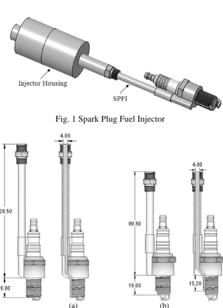
Fig. 1 Spark Plug Fuel Injector
(a) (b)
Fig. 2 (a) Original SPFI and (b) Modified SPFI (all units in mm)
Compressed natural gas direct injection (CNGDI) is achieved by combining the fuel injector with a market-available spark plug, which is known as spark plug fuel injector (SPFI). It is a low cost conversion system that can convert any type of spark injection gasoline engine to CNGDI. In conventional practice, converting to direct injection requires modifications or replacing the cylinder head with extra holes for fuel injectors and possibly modifying the piston crowns. Therefore, it willinvolve high conversion cost because fabricating the new cylinder head involves new mould design and many costly manufacturing processes. By using this SPFI, high conversion cost can be avoided because no modification on the original engine structure and spark plug placement are required. The SPFI is a technically easier and cheaper conversion system by only replacing the existing spark plug with SPFI. As a result, users will not only benefit from an alternative low cost CNGDI conversion, but also can enhance the engine performance by using direct injection system compared to currently available conversion kits with port injection fuel system.
In addition to the above-mentioned benefits, SPFI also can be utilized for dual-fuel system in the internal combustion (IC) engines such as gasoline-CNG, gasoline-hydrogen and CNG-hydrogen by recalibrating the engine control unit (ECU). Therefore, it will be able to solve the problem of unavailability of CNG refuelling stations in certain places and reduce the environment pollution problems by using hydrogen fuels [8]. However, two effects were noticed when SPFI was installed in an engine. First is the reduction of effective compression ratio and second is fuel delivery delay with respect to start of injection (SOI). These behaviours were due to the length of SPFI fuel path
where it caused the effective total cylinder volume and fuel delivery time increased [9]. These problems can be solved by shortening the SPFI fuel path, as well as adjusting the injection and ignition timings of SPFI system. The SPFI design and prototype are presented in Fig.1. In order to reduce the length of fuel path and pressure loss within in SPFI, an adjustment of fuel path was undertaken to reduce the fuel delivery delay in the engine combustion chamber [9]. The modification works involved shortening the fuel path from 147.50 millimeters to 114.70 millimeters. To reduce pressure loss, the cross-sectional area of bored section before it reaches the SPFI nozzle was expanded and the inner diameter of the fuel path that connected to the spark plug was made wider as 4.0 millimeters. However, a small cylinder fuel path with 2.0 millimeters diameter section connecting fuel path with bored section was unchanged. This was a measure to quench the combustion in order to avoid the combustion to penetrate into the SPFI fuel path. As a result, the fuel arrival delay time was shortened and pressure loss was reduced. Fig. 2 shows the original and adjusted SPFI. The adjusted final SPFI has shorter and wider overall fuel path, but with a bored section in the fuel path narrowing to the quenching distance of methane-air combustion. The hatched area in the drawing shows the cross-sectional area of fuel paths.
III. EXPERIMENTAL METHODS
The distance of the fuel path of the SPFI between the gasoline direct injection (GDI) injector nozzle and the SPFI nozzle causes the delay in the fuel delivery process to the engine cylinder. An experiment was carried out to measure and compare the fuel delay time between the original and the modified SPFI as shown in Fig. 2above with same injection timing and pressure. The tip of the SPFI and the measurement scale were immersed in a beaker of water to establish a reference for the size of the jets from the SPFI nozzle. The nonflammable compressed pure nitrogen gas was used as compressed natural gas substitute for safety purpose. The gas was injected at 40, 50 and 60 bar pressure and the gas jets were formed as a bubble when the gas exited at the nozzle of the SPFI. The images of the gas jets after the SOI were captured with a digital camera. The fuel injector was synchronized with a flash light using a control circuit which consists of a metal-oxide-semiconductor field-effect transistor (MOSFET) and two pulse generators.
Fig. 3 Schematic of gas jet measurement test
IV. RESULTS
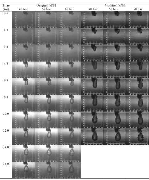
The images of the gas jets for both original and modified SPFI at different injection pressures and time after SOI are shown in Fig. 4. The experiment was done for both SPFI designs at 12 ms injection time with 40, 50 and 60 bar injection pressures. The figure shows that the time for the first appearance of gas jet was found to be 0.5 ms in all cases. However, the appearances of the initial gas jets from the original SPFI were relatively small compared to the gas jets of the modified SPFI. The reason was due to the longer fuel path length of the original SPFI which caused more pressure loss and subsequently a longer fuel delivery time. The size of the gas jets progressed to full-developed at 14 ms for the original SPFI after SOI for all the injection pressures, meanwhile the gas jet from the modified SPFI took 10 ms to fully developed.
Fig. 4 Images of gas jets from various injection pressures versus time after SOI for original [10] and modified SPFI
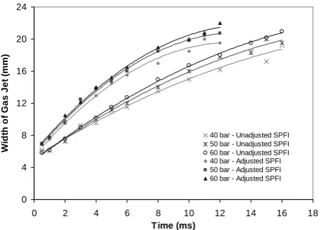
The comparison between the length and width of gas jets for unadjusted and adjusted SPFI from all injection pressures at different time after SOI are shown in Fig. 5 and Fig. 6. The development of length and width of the gas jets were identical up to 2 ms, but diverged as time further progressed. At 60 bar injection pressure, the length and width of the fully developed gas jet at 10 ms were 47.0 mm and 20.0 mm respectively for modified SPFI. For the same conditions, for the original SPFI, the length and width of the fully developed gas jet at 14 ms were 41.5 mm and 19.5 mm respectively. The results showed that the gas jets of the original SPFI were 11.70% and 2.5% shorter and narrower than that of gas jet of the modified SPFI.
In addition, the results showed that higher injection pressure resulted in longer and wider gas jets. For the original SPFI, the length of the fully developed gas jets at 40 and 50 bar injection pressure were 10.84% and 4.82% respectively shorter as compared to 60 bar injection pressure. In terms of gas jet width, the 40 and 50 bar injection gas jets were 5.13% and 4.10% narrower than that of 60 bar injection pressure. Meanwhile, for the modified SPFI at similar condition, there was a reduction of 12.77% and 6.38% respectively of fully developed gas jets length with 40 and 50 bar injection pressure was found. In relation to gas jet width, the 40 and 50 bar injection gas jets were 7.50% and 1.00% narrower.
Furthermore, the results also showed that the original SPFI took approximately 16 ms to complete the fuel delivery in the water surroundings, while the modified SPFI achieved improvement with a shorter 12 ms fuel delivery time as indicated by the bubbles detachment from the both SPFI designs. However, in the injection process into compressed air as in the engine cylinder, it is expected that SPFI will take significantly shorter time to complete the fuel delivery process because air is less dense and viscous. All the results showed that the SPFI with adjustment of fuel path successfully achieved shorter delivery delay time and less pressure loss. Besides, the cylinder effective volume was reduced with shorter fuel path length of SPFI. As a result, the reduction of compression ratio and peak pressure engine can be minimized.
0 5 10 15 20 25 30 35 40 45 50
0 2 4 6 8 10 12 14 16 18
Time (ms)
L
eng
th
of
Ga
s J
e
t (
m
m)
[image:3.595.48.289.475.765.2]40 bar - Unadjusted SPFI 50 bar - Unadjusted SPFI 60 bar - Unadjusted SPFI 40 bar - Adjusted SPFI 50 bar - Adjusted SPFI 60 bar - Adjusted SPFI
[image:3.595.314.542.571.731.2]0 4 8 12 16 20 24
0 2 4 6 8 10 12 14 16 18
Time (ms)
W
idt
h of
G
as Jet
(
m
m
)
[image:4.595.55.285.53.218.2]40 bar - Unadjusted SPFI 50 bar - Unadjusted SPFI 60 bar - Unadjusted SPFI 40 bar - Adjusted SPFI 50 bar - Adjusted SPFI 60 bar - Adjusted SPFI
Fig. 6 Comparison of gas jets length vs. time for the original and the modified SPFI with different injection pressures
[image:4.595.53.289.448.702.2]In addition, the results showed that the shape of fully developed gas jet from SPFI in liquid environment was in agreement with the shape of vortex ball model [1] as shown in Fig. 7 and gas jet of SPFI in air environment by using PLIF method [10]. The length and cone angle of fully developed gas jet penetration of the adjusted SPFI at 50 bar injection pressure and 12 ms injection time were around 100 mm and 13º respectively in air environment [9] as presented in Fig. 8(a). Meanwhile, at the same conditions, the gas jet with 44 mm of penetration depth and 20º of cone angle was found in water environment as shown in Fig. 8(b). The results showed that gas jet penetration of SPFI in liquid environment was shorter in depth and bigger in cone angle size due to the density and viscosity of water is higher than air.
Fig. 7 The vortex ball model [1]
(a) (b)
Fig. 8 Fully developed gas jet of SPFI: (a) In air environment [9] (b) In liquid environment
V. CONCLUSION
In conclusion, the measurements of gas jet in a liquid environment were successfully conducted and the results were in agreement with vortex ball model by Boyan &
Furuyama [1], but with different degree in size due to different density and viscosity of the injection environments. The gas jet penetration of SPFI in water was shorter in depth and bigger in cone angle compared to the gas jet in air environment due to the higher density and viscosity of water. It was also showed that SPFI with shorter and wider fuel path achieved improvement of faster jet development due to less pressure loss. Results showed that the gas jets of the original SPFI were 11.70% and 2.5% shorter and narrower than that of modified SPFI, and higher injection pressure resulted in longer and wider gas jets. This investigation of gas jet structure in water must be further elaborated with different water pressure in order to reach governing equations and ultimately correlated to the establish model for predicting the gas injection behaviour in engine. This technique could possibly be a low cost alternative to laser optical diagnostics for gaseous flow.
ACKNOWLEDGMENT
The authors would like to express their appreciation to Ministry of Science, Technology and Innovation (MOSTI) and National University of Malaysia for funding this work under the project code UKM-GUP-BTT-07-25-157.
NOMENCLATURE
CNGDI Compressed natural gas direct injection ECU Engine control unit
FDI Fuel direct injection GDI Gasoline direct injection
IC Internal combustion
LDA Laser Doppler anemometry MOSFE
T
Metal-oxide-semiconductor field-effect transistor
NMOG Non methane organic gasses PIV Particle image Velocimetry PLIF Planar laser-induced fluorescent
SI Spark ignition
SOI Start of injection SPFI Spark plug fuel injector
REFERENCES
[1] X. Boyan and M. Furuyama, "Jet characteristics of CNG injector with MPI system," JSAE Review, vol. 19, pp. 229-234, 1998.
[2] M. Ishii, S. Ishizawa, E. Inada, R. Idoguchi, and T. Sekiba, "Experimental Studies on Natural Gas Vehicles," SAE Technical Paper 942005, 1994.
[3] S. Shiga, S. Ozone, H. T. C. Machacon, T. Karasawa, N. H., T. Ueda, N. Jingu, Z. Huang, M. Tsue, and M. Kono, "A Study of the Combustion and Emission Characteristic of a Compressed-Natural-Gas Direct Injection Stratified Combustion Using a Rapid-Compression-Machine," Combustion and Flame, vol. 129, pp. 1-10, 2002.
[5] A. Argarwal and D. Assanis, "Multi-dimensional modeling of Ignition, Combustion and Nitric Oxide Formation in Direct Injection Natural Gas Engines," SAE Technical 2000-01-1839, 2000.
[6] N. A. Halliwell and G. K. Hargrave, "Optical Engineering: Diagnostics for Industrial Applications," Proceedings of the Institution of Mechanical Engineers, Part C: Journal of Mechanical Engineering Science, vol. 217, pp. 597-618, 2003.
[7] C. Schulz and V. Sick, "Tracer-LIF Diagnostics: Quantitative Measurement of Fuel Concentration, Temperature and Fuel/Air Ratio
in Practical Combustion Systems," Progress in Energy and
Combustion Science, vol. 31, pp. 75-121, 2005.
[8] H. G. How, T. I. Mohamad, and S. Abdullah, "Development of a Spark Plug Fuel Injector (SPFI) for Compressed Natural Gas Direct Injection In a 4-Cylinder Spark Ignition Engine," in 2nd Regional Conference on Vehicle Engineering and Technology, Kuala Lumpur, Malaysia, 2008, pp. 1-6.
[9] T. I. Mohamad, "Development of a Spark Plug Fuel Injector for Direct Injection of methane in Spark Ignition Engine," in School of Engineering. vol. PhD Cranfield: Cranfield University, 2006, p. 198. [10] H. G. How, T. I. Mohamad, and S. Abdullah, "The Structure of Gas Jet
from a Spark Plug Fuel Injector (SPFI) in a Liquid Environment," in