BER Performance of Space-Time Coded MMSE DFE for
Wideband Code Division Multiple Access (WCDMA)
Sanjay Kumar SHARMA1, S. Naseem AHMAD2
1
Dept. of Electronics and Communication Engg., Krishna Institute of Engg. and Technology, Ghaziabad, India 2
Dept. of Electronics and Communication Engg, Jamia Millia Islamia, Delhi, India Email: sanjaysharma1515@yahoo.co.in
Received January 20, 2009; revised March 1, 2009; accepted April 27, 2009
ABSTRACT
In recent times, there has been growing interests in integration of voice, data and video traffic in wireless communication networks. With these growing interests, WCDMA has immerged as an attractive access technique. The performance of WCDMA system is deteriorated in presence of multipath fading environment. The paper presents space-time coded minimum mean square error (MMSE) Decision Feedback Equalizer (DFE) for wideband code division multiple access (WCDMA) in a frequency selective channel. The filter coefficients in MMSE DFE are optimized to suppress noise, intersymbol interference (ISI), and multiple ac-cess interference (MAI) with reasonable system complexity. For the above structure, we have presented the estimation of BER for a MMSE DFE using computer simulation experiments. The simulation includes the effects of additive white Gaussian noise, multipath fading and multiple access interference (MAI). Further-more, the performance is compared with standard linear equalizer (LE) and RAKE receiver. Numerical and simulation results show that the MMSE DFE exhibits significant performance improvement over the stan-dard linear equalizer (LE) and RAKE receiver.
Keywords: Decision Feedback Equalizer, Multiple Access Interference (MAI), RAKE Receiver, Transmit Diversity, Wideband Code-Division Multiple-Access (WCDMA), Bit Error Rate (BER)
1. Introduction
During the period of last one decade, the large demands for wireless services and high data speeds have driven the wireless cellular networks to a tremendous growth. These large demands require some advanced techniques like WCDMA that can support more users and higher data rates. WCDMA has been accepted as standard ac-cess method for the third and fourth generation wireless systems. The WCDMA system assigns each user a spe-cific signature sequence from the signature set. One lim-iting factor in the capacity (i.e. the number of users) of the WCDMA systems is the multiple access interference (MAI). In fact, in WCDMA system, multiple access in-terference (MAI) and intersymbol inin-terference (ISI) are caused by multipath dispersion and are major problems. These problems cannot be efficiently suppressed by
conventional RAKE receivers. The MAI caused by one user is usually small, but as the number of interferers or their power increases, effect of MAI becomes noticeable. To alleviate the effect of MAI, a number of multiple user detection methods have been proposed in literature in recent years [1]. Usually, the multiuser receiver can per-form much better than the conventional correlator based receiver, but at the cost of increased system complexity. For uplink channel, the increased complexity is not a big issue since the base station may be equipped with some powerful computing processors. Whereas, a mobile ter-minal is limited by cost and size. Therefore, it will be very difficult to use the multiuser receiver for the downlink channel. But, irrespective of this problem, there is a strong emphasis to improve the performance of the downlink channel in WCDMA.
DIVISION MULTIPLE ACCESS (WCDMA)
diversity. In WCDMA systems, two methods of spatial diversity and interference cancellation can be combined to increase the system performance and capacity. The combination of MUD and receive diversity techniques has been proposed in [2,3]. In third generation WCDMA systems, the processing transmit gain may be very small. This makes the use of diversity quite effective. Transmit diversity can be used to alleviate fading efficiently. There are several forms of transmit diversity. In open- loop scenarios, where the transmitter does not have the channel state information, space-time transmit diversity (STTD) is generally used. When channel state informa-tion is available, closed-loop transmit diversity such as beam forming can be used. Over the period of last dec-ade, various transmit diversity schemes have been pro-posed in modern wireless communications to combat fading. Among various proposed techniques, Alamouti’s space-time block code [4], called as space- time transmit diversity (STTD), is one of the most effective solutions for two transmit antennas. Because of its effectiveness, Alamouti’s space-time block code has been adopted for third generation WCDMA systems in indoor applications for high data rate.
WCDMA downlink has two interesting features. One is that all transmissions are synchronized and the other is that the spreading codes can be orthogonal. By taking advantages of these features, the chip-level equalization has been proposed to mitigate MAI with a despreader [5, 6]. A despreader can mitigate the MAI after chip-level equalization to restore the orthogonality. In [7], it has been shown that a receiver with a chip-level equalizer can be easily implemented with adaptive algorithms. Unfortunately, the performance of the receiver with a chip-level linear equalizer (LE) is not significantly better than the rake receiver, unless the receiver of the mobile station is equipped with multiple receiving antennas or uses over sampling. Because the LE cannot perfectly suppress the miltiptah interference with a single receive antenna and chip rate sampling, a residual multipath in-terference exists. Thus, the MAI cannot be completely removed by the correlator or despreder. To avoid this, multiple receive antennas or a higher sampling rate can be used for the chip level minimum mean square error linear equalizer (MMSE-LE) [10]. Decision feedback equalization is a powerful equalization technique that provides postcursor ISI cancellation with reduced noise enhancement and is widely used to offer better steady- state performance than a linear equalizer (LE). Recent research has been devoted to the receiver design using zero forcing [11], minimum MSE (MMSE) [12] meth-ods.
The zero forcing receivers can completely suppress the ISI and multi-user interference under certain conditions. However, explicit knowledge of all the signature
wave-forms is required and the noise may be enhanced. Hence, the receiver designed by using the MMSE criterion seems to be better than zero-forcing receivers in terms of their bit error rate (BER) performance. In this paper, we investigate and analyze a minimum mean-square error (MMSE) decision feedback equalizer (DFE) for space- time coded WCDMA downlink channel to achieve better performance than the chip level LE and a RAKE receiver in a frequency selective channel.
The rest of the paper is organized as follows. The sig-nals and system models have been introduced in section 2.In subsection 2.1 we have discussed the basic space- time encoder in WCDMA. In subsection 2.2,we have presented the structure of a traditional decision feedback equalizer (DFE). The space-time coded decision feed-back equalizer (DFE) has been formulated in subsection 2.3. Subsection 2.4 presents the mathematical analysis. In section 3, we have formulated the simulation envi-ronments. Computer simulation results are presented in section 4 to see the performance and we conclude the paper with some remarks in section 5.
2. Signal and System Models
2.1. Basic Space-Time Encoder in WCDMA
Figure 1 shows the basic space-time transmit diversity (STTD) encoder in WCDMA. We consider two symbols periods, 0 and 1, over which two symbols are sent. Dur-ing symbol period 0, symbol c0 is sent on transmit an-tenna A and c1* is sent on antenna B.
During symbol period 1, c1 is sent on transmit antenna A and c0* is sent on antenna B. It is assumed that the same channelization code is used to send these STTD encoded symbols. But, the pseudo-random scrambling codes are different for different symbol periods. Let hji(t)
denote the continuous-time impulse response of the multi-path channel from transmitter antenna i to the receive an-tenna j. A time-variant multipath signal propagation through the mobile cellular radio channel can be modeled as:
hji(t)= , (1)
1
( )
, ,
0
( ) ji q ( ( ))
Q
j t
ji q ji q
q
t e t t
where Q is the number of ch nnel multipath, a
(
)
isthe Dirac-delta function, and ji, q(t), ji, q(t) and ji, q(t)
are the time-variant attenuation, phase distortion and propagation delay of the qth path from transmit antenna i to receive antenna j, respectively.
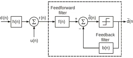
2.2. Traditional Decision Feedback Equalizer
We first describe a traditional decision feedback equal-izer (DFE) receiver, upon which a two dimensional DFE for WCDMA system builds. Figure 2 shows a discrete- time complex base band model for the conventional DFE. The DFE consists of a feed forward filter f(n) and a feedback filter b(n), where n is the symbol index. Since the feedback filter sits in a feedback loop, it must be strictly causal. The signal propagates through a discrete time-variant frequency selective fading channel h(n).
Also, r(n) → received signal, d(n) → transmitted symbols information, d nˆ( ) → output of DFE.
2.3. Space-Time Coded Decision Feedback Equalizer (DFE)
We concentrate on WCDMA downlink channel with transmit diversity. The system employs two transmit antennas at the transmitter side and one receive antenna at the receiver side. We assume that there are K active users in the cell under consideration and that the inter- cell interference is negligibly small in cellular scenario. Also, there are M transmit antennas and V receive an-tennas in the system.
Now, the transmitted signal of user k from antenna m,
represented by xk( )m( )t , is given by
( ) ( )
m k
x t =
1 ( )
, 0
( ) ( )
N
m
k k k n s
n
A c n w t nT
(2)where, , n = 0, …., N-1, is the kth user’s space- time coded data sequence to be transmitted from antenna m within a specific time-frame
( )
( )
m k
c
n
Akis the average amplitude of the kth user
Ts is the symbol duration
wk,n(t) is the signature waveform of user k at the nth
symbol period
b(n) Feedback
filter
d(n)~ d(n)
r (n) f(n) Feedforward
filter +
– h(n)
d (n)
[image:3.595.58.283.605.703.2]u(n)
Figure 2. The traditional DFE structure.
The signature waveform wk,n(t)is represented as
, ( ) k n
w t =
1
, 0 1
( ) ( )
G
k n c
i
s i p t iT
G
(3)where G is the processing gain, Tc is the chip duration,
p(t) is the chip pulse shape signal sk,n(i) is the kth user’s signature sequence
The spread signal is transmitted over the frequency and time selective channels. The channels from the two base station antennas to the receiver are modeled as Rayleigh multipath fading channels. Then, according to basic equation (1), the impulse response of the channels between the base station transmitter and the mobile sta-tion receiver is
h(m)(t) = (4) 1
( )
0
( ), 1,
Q m
q q
q
h t t m
2)
k
where Q is the number of paths,
hq(m) is a complex coefficient which is used to model
the qth path
tq is the delay related to the qth path.
We assume that the number of paths and their delay times are equal for the two channels. Finally, the re-ceived signal from all K users at a mobile base station after demodulation is given by
r(t) = (5)
1 1
2
( ) ( )
1 0 0
( ) (
Q K
m m
q k q
m q k
h x t t u t
where u(t) is the additive white Gaussian noise (AWGN) with noise variance of 2.
It may be more convenient to consider a discrete-time signal model. Accordingly, the received signal sequence is written as
r(n) = (6)
1 1
2
( ) ( )
1 0 0
Q K
m m
q k q
m q k
h x u
where r(n) is the received signal sequence, and uk is the
white noise sequence.
2.4. Mathematical Analysis
To achieve transmit diversity; we use Alamouti’s space- time block code for two transmit and one receive anten-nas [4]. In a space-time block-level encoding scheme, each block of 2N information symbols dk(n), n = 0, ….,
2N-1, is split into two blocks of odd and even symbols, each having length N. Further, these two blocks are space-time encoded and transmitted during two subse-quent periods, each having a duration of NTs. This means
DIVISION MULTIPLE ACCESS (WCDMA)
v
(1)
(2)
(1) *
(2) *
( ) (2 )
( ) (2 1)
( ) (2 1)
( ) (2 )
k k
k k
k k
k k
c n d n
c n d n
c n N d n
c n N d n
(7)
where n = 0, ……, N–1.
If we place a guard-time tg between two transmission
periods, the received signal r(t) consist of two non- in-terfering signals. Now, let do(2n) and do(2n + 1) be the
desired symbols to be detected at the receiver. According to Figure 2, r(t) is first allowed to pass through the two matched filters which are matched to the corresponding spreading waveforms of the user and then sampled at times tv, v = 0, …, i – 1. Then, we have
r1 = *0, (8) 0
( ) ( )
sT
n s
w r nT t d
r2 =
* *
0, 0
( ) ( ( ) )
sT
n N s v g
w r n N T t t d
(9) For ideal correlation properties of signature wave-forms, there shall be no ISI and MAI in above samples. Thus, in ideal scenario, a RAKE receiver and a linear equalizer (LE) can work as optimum receiver [8]. But, in practice, because of non-zero auto and cross-correlations of the shifted signature waveforms, ISI and MAI occur and hence the performance of a RAKE receiver deterio-rates in highly interference environments. Thus, to achieve the performance improvement, we use a space- time coded DFE structure with two transmit and one re-ceive antenna as shown in Figure 3. Now, the input to the first decision part, to detect d0(2n), is written as
de=
1
11 1, 21 2,
0
[ ( 1 ) ( 1 ) ]
L f
f q f q
q
f L q r f L q r
+11 21
1
ˆ ˆ
[ ( ) (2 2 ) ( ) (2 2 1)
Lb
b o b o
m
b L m d n m b L m d n m
](10) The expression in equation (10) may be written in ma-trix form as under:
de = FH Y (11)
Here,
FH= [f11(Lf – 1), … , f11(0), f21(Lf – 1), …..,
f21(0), b11(Lb – 1), … , b11(0), b21(Lb – 1), ….., b21(0)]
(12)
And
Y= [r1, 0, ….., r1, Lf – 1, r2, 0, ….., r2, Lf – 1, do(2n–2)
….., do(2n – 2Lb), d0(2n – 1), ….., do(2n – 2Lb + 1)]
J
(13) The mean square error (MSE) is given by
= E {|d – do (2n)|2}
Now, to achieve the performance improvement, we have to minimize the mean square error (MSE). For that purpose, we must decide appropriate value of weight vector. The solution to the MMSE problem is given by
FH= A–1 G (14) where A= E.{ Y Y H} (15) and G = E{ Y Y do*(2n)} (16)
To determine matrix A and vector G, we must know the channel model and also we assume that the interfer-ing user’s signature codes and all the information sym-bols are independent random sequences. Now, the mini-mum mean-square error for the system can be written as
min= 1 – G HS–1 G (17) We can estimate the overall signal-to-noise ratio per symbol, using the Gaussian approximation, from the MMSE as [9]
SNR = (1 – min) /min (18) Hence, the bit error rate (BER) can be approximated as under:
Pe = Q( SNR)
Pe = Q( (1G A GH 1 ) /G A GH 1 )
From above expression, it is obvious that Pe depends
upon the coefficients of the channel and signature wave-form of the desired user.
3. Simulation Environments
We study the performance of a chip-rate DFE in a WCDMA downlink channel using QPSK modulation scheme and a spreading factor of 32. We have assumed Rayleigh fading channels and channel coefficients as complex Gaussian random variables. The system trans-mits the data at 480 kbps, and the frame structure of 10ms duration includes 15 slots. Each slot consists of 160 QPSK symbols that are spread by the Walsh-Had-mard code with period 32. As a whole, a chip rate of 3.84 Mc/s is used. The channel taps are each subject to the Rayleigh fading around their mean value. Throughout the simulation work, the estimation is performed at S/N = 10 dB. We assume 16 active users within the same cell/frequency. However, the actual number of users may
e more depending upon the service. b
Dete
c
ti
o
n
D
e
vi
ce
T
ran
s
m
is
s
ion
Del
a
y Signature waveform matched
filter
Signature waveform matched
filter
t = t v
iTs
t = t v
Feed forward
filters f m,v {1, 2}
mv
iTs
d[2n]
Feedback filters b , m,v {1, 2}mv de
do
d[2n+1] Output decision r1
r2 Rx
+
S
pac
e-ti
m
e
e
n
c
o
ding
on
blo
c
k
le
v
e
l
Co
ns
tell
at
ion
map
p
in
g
Hi
gh
r
a
te
dat
a s
tr
e
am
{d
(n
)}
Tx1
Tx2
Transmitter Receiver
DFE
Figure 3. System model.
4.
Simulation
Results
For two transmit antenna structure shown in figure 3, the feed forward filters are represented by fmv(n), m, v {1,
2}, each having Lf taps and sampling is performed at i
times the chip rate. Also, the feedback filters are repre-sented by bmv(n) , m, v{1, 2}, each having Lb taps and
operating at the symbol rate. Throughout the simulation work, the Rayleigh fading channel uses Q = 3 paths and the number of DFE feed-forward taps, Lf is equal to four.
Because of shorter length of channel memory than the period of symbols, it is evident that ISI is produced only by the adjacent symbols. Thus, the DFE feedback filters each requires only single tap. This means that we take Lb
= 1. Further, simulation has been performed on over 4000 blocks each consisting of 800 space-time coded symbols and also channel is assumed constant during each frame.
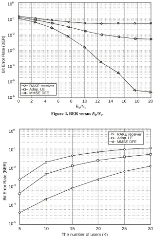
In Figure 4, the bit error rate (BER) has been plotted as a function of average signal to noise per bit (Eb/No) for
Rake receiver, adaptive linear equalizer (LE) and DFE with two transmit antennas (two dimensional DFE) and one receive antenna. In this case, we have assumed 3-paths channels and 16 active users within the cell of interest. Also, the number of feed-forward taps, Lf for
[image:5.595.59.547.76.248.2]two-dimensional DFE has been taken equal to 4. Simu-lation has been performed on over 4000 blocks each consisting of 800 space-time coded symbols. From Figure 4, it may be observed that as Eb/No increases,
BER of DFE fall faster than RAKE and linear equalizer. At higher values of Eb/No, the MAI dominates and the
performance curve of RAKE receiver approaches a saturation level. At this point, significant performance improvement is achieved by DFE. In Figure 5, the bit error rate (BER) has been plotted as a function of num-ber of active users for Rake receiver, adaptive linear equalizer (LE) and DFE with two transmit antennas (two dimensional DFE) and one receive antenna at Eb/No = 20dB. In this case also, we have assumed
3-paths channels and the number of feed-forward taps, Lf for two-dimensional DFE has been taken equal to 5.
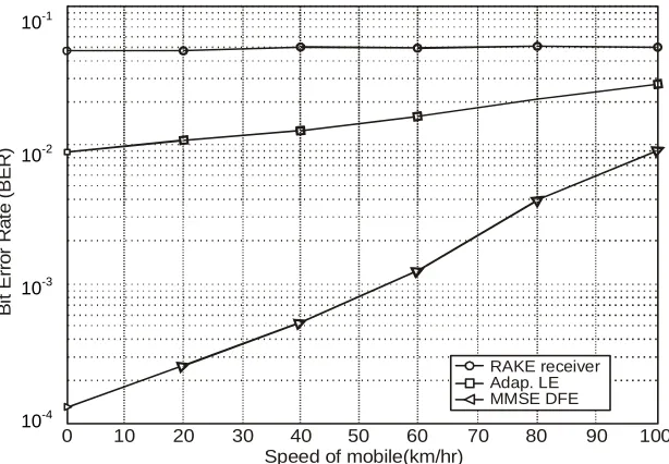
It can be observed as the number of users increases, MMSE DFE offers better performance than Rake re-ceiver, adaptive linear equalizer (LE). Figure 6 reveals that as the speed of the mobile becomes higher, it is more difficult for the equalizer to manage successfully the variation of channel. It results in the increase of MAI in the receivers. Consequently, the performance of the DFE deteriorates as the speed of the mobile be-comes higher. Also, the variation of the channel does not affect the performance of the rake receiver since the performance degradation is only due to the channel estimation error.
Table 1. List of parameters for simulation.
S. No. Simulation Parameter Value
1 Carrier frequency 2 GHz
2 Modulation technique QPSK
3 Data Rate 480 kbps
4 Processing gain 32
5 Signature or Spreading code Walsh-Hadamard Code
6 Number of multipaths 3
7 Number of feed forward taps 4
8 Number of feedback filter taps 1
9 Chip rate 3.84 Mc/s
10 No. of transmit antenna 2
11 No. of receive antennas 1
12 Performance parameter BER
[image:5.595.60.287.500.714.2]DIVISION MULTIPLE ACCESS (WCDMA)
5. Conclusions
In the paper, we have investigated the receiver using MMSE DFE for WCDMA downlink with space-time transmit diversity in a frequency selective channel. Bit error rate (BER) of various systems has been calculated using Gaussian approximation. In simulation curves, we have shown the BER performances with respect to the number of users, Eb/No and mobile speed. It is observed
that with the increase in number of transmissions, the performance of all the receivers, i.e., adaptive LE, the Rake and the DFE, becomes worse because of increase in intersymbol interference (ISI) and multiple access interference (MAI). According to simulation curves, a MMSE DFE outperforms an adaptive LE and a RAKE receiver for the large number of users and also when BER is compared with respect to the Eb/No values. This
happens because a MMSE DFE suppresses interference
RAKE receiver Adap. LE MMSE DFE
10? 0
B
it
E
rror R
a
te (B
E
R
)
10? 10? 10? 10? 10? 100
2 4 6 8 10 12 14 16 18 20
E /Nb o
100
10-1
10-2
10-3
10-4
10-5
[image:6.595.139.453.210.695.2]10-6
Figure 4. BER versus Eb/No.
10
RAKE receiver Adap. LE MMSE DFE
0
5 10 15 20 25 30
B
it
Erro
r
R
a
te
(BE
R
)
The number of users (K)
10?
10?
10?
10?
10?
100
10-1
10-2
10-3
10-4
[image:6.595.143.453.212.439.2]10-5
10
B
it E
rr
o
r
R
a
te
(B
E
R
)
Speed of mobile(km/hr)
0 10 20 30 40 50 60 70 80 90 10 10?
10?
10?
10-1
-2
-3
10
10
10-4
0
[image:7.595.144.451.82.295.2]RAKE receiver Adap. LE MMSE DFE
Figure 6. BER performance with respect to the speed of the mobile.
more efficiently compared to an adaptive LE and a RAKE receiver. It is also concluded that the structure of space-time coded MMSF DFE, when compared to other schemes of similar complexity, provides a reasonable balance between noise, ISI and MAI. Thus, this scheme works well when any of these three problems dominates. However, at very high interference levels, the use of transmit diversity does not improve the performance, unless the interference is suppressed by more sophisti-cated methods such as multi-user detection. As a whole, it is concluded that, in a wireless system, equalization, diversity, and STBC coding can be used together to boost the received signal quality and link performance. Although the system with only two transmit antennas is investigated here, it can be straightforwardly extended to a system with more transmit antennas. All these elegant results can be used for evaluating the system capacity, designing power control algorithms and appropriate channel coding techniques for WCDMA.
7. References
[1] S. Verdu, “Multiuser detection,” Cambridge University Press, New York, 1998.
[2] S. M. Razavizadeh, V. T. T. Vakili, and P. Azmi, “Com-parison of several multiple antenna multiuser detectors in wireless CDMA system,” in Proceedings of the 5th IFIP TC6 Conference on Mobile and Wireless Networks (MWCN2003), 2003.
[3] Z. Zvonar, “Combined multiuser detection and diversity reception for wireless CDMA system,” IEEE Transac-tions on Vehicular Technology, Vol. 45, pp. 205-211, February 1996.
[4] S. M. Alamouti, “A simple transmit diversity technique
for wireless communication,” IEEE Journal on Selected Areas in Communications, Vol.16, No. 8, pp. 1451-1458, October 1998.
[5] C. D. Frank and E. Visotsky, “Adaptive interference sup-pression for direct-sequence CDMA systems with long spreading codes,” presented at the 36th Allerton Confer-ence, 1998.
[6] A. Klein, “Data detection algorithms specially designed for the downlink of CDMA mobile radio system,” in Proceedings of IEEE VTC-1997, pp. 203-207, 1997.
[7] F. Petre, M. Moonen, M. Engels, B. Gyselincky, and H. D. Man, “Pilot-aided adaptive chip equalizer receiver for interference suppression in DS-CDMA forward link,” in Proceedings of IEEE VTC-Fall 2000, pp. 303-308, 2000.
[8] J. Wang and K. Yao, “Space-time coded wideband CDMA system,” in Proceedings of VTC 2002, Vol. 1, pp. 260-264, Spring 2002.
[9] M. Abdulrahman, A. U. H. Sheikh, and D. D. Falconer, “Decision feedback equalization for CDMA in indoors wireless communication,” IEEE Journal on Selected Ar-eas in Communications, Vol. 12, No. 4, pp. 698-706, May 1994.
[10] T. Udomsripariboon, C. Mingukwan, C. Benjangkaprasert, O. Sangaroon, and K. Janchitrapongvej, “Soft output deci-sion feedback equalizer using variable step-size algorithm for turbo codes DS/CDMA systems,” in Proceedings of IEEE ISPACS, pp. 505-508, December 2005.
[11]S. Haykin and M. Moher, “Modern wireless communica-tions,” Prentice-Hall, 2005.