ISSN Online: 2333-9721 ISSN Print: 2333-9705
DOI: 10.4236/oalib.1105891 Nov. 13, 2019 1 Open Access Library Journal
Design of PLC Control System for Automatic
Door
Jiangshan Gao, Yan Zhi
College of Mechanical and Control Engineering, Guilin University of Technology, Guilin, China
Abstract
The core of automatic door is its control system. The basic principle of auto-matic door control system is to use PLC to output digital signal and analog signal to inverter to change working power frequency and drive motor steer-ing, drive motor frequency conversion, change direction operation, drive au-tomatic door to realize door opening and closing operations at different speeds. When the signal acquisition device of the automatic door detects whether a person or an object has passed, the automatic door can be auto-matically opened and closed to realize the function of the person coming to the door and the person to close the door. The system designed in this paper not only completes the opening and closing of the automatic door at different speeds under different conditions, but also adds more safety protection, such as anti-pinch control, emergency stop and system fault self-test, to achieve the expected design effect. The automatic door control system has the characte-ristics of higher safety, ease of use and stability.
Subject Areas
Mechanical Engineering
Keywords
Automatic Door, PLC, Signal Acquisition Device, Frequency
1. Introduction
The figure of the automatic door in life can be seen everywhere. The main working principle of the automatic door is to sense whether there is an object passing through the sensing device at the top of the door and the auxiliary infra-red sensing device on the side of the door frame, giving the door a switch signal and then programmable control. The device, the frequency converter, the drive
How to cite this paper: Gao, J.S. and Zhi, Y. (2019) Design of PLC Control System for Automatic Door. Open Access Library Journal, 6: e5891.
https://doi.org/10.4236/oalib.1105891
Received: October 30, 2019 Accepted: November 10, 2019 Published: November 13, 2019
Copyright © 2019 by author(s) and Open Access Library Inc.
This work is licensed under the Creative Commons Attribution International License (CC BY 4.0).
DOI: 10.4236/oalib.1105891 2 Open Access Library Journal
atively simple [1]. These can determine the automatic door, the stability and safety of operation, so China needs to strengthen the research of control system, combined with the foreign automatic door function and local actual needs, using advanced software compilation, solving various problems existing in the devel-opment process of automatic door, and promoting the automatic door industry.
The design of this paper is an automatic door applied to public places such as shopping malls and high-end hotel entrances and exits, which require strong security and practicality. Integrating automatic door scenes and usage habits in daily life, this paper designs the most used automatic sliding door [2]. The tomatic sliding door uses the inductive switch and safety grating to realize au-tomatic control. At the same time, the manual control is realized by using the operation buttons, and the use is made. Auxiliary devices such as backup power supply to meet the needs of different situations of adult traffic.
2. System Design
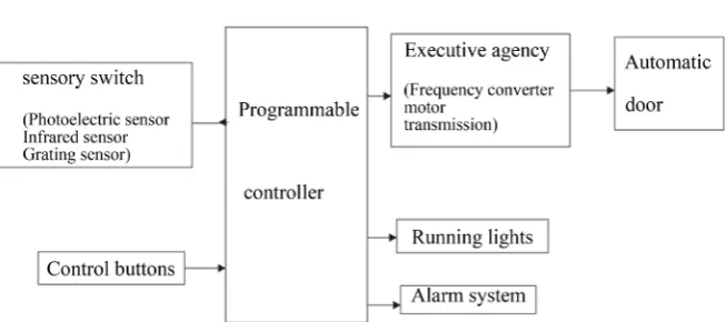
The design of the automatic door needs to be considered for the purpose of safety and simplicity. This design is applied to public places with large traffic flow. It is designed to take care of the practicality of practical use and improve convenience [3]. The design of automatic door control system based on PLC needs to consider the practicality and safety in real life, and ensure the safety of the passing object under the guarantee of smooth operation of the automatic door. This paper adopts the photoelectric sensor to collect whether the object passes the signal to the PLC, and controls the opening and closing of the auto-matic door through the inverter, the driving motor and the transmission device in the PLC control actuator; meanwhile, the infrared sensor is opened after the automatic door is opened. Let the relevant implementing agencies coordinate work to ensure that the automatic door can operate normally and safely, as shown in Figure 1.
DOI: 10.4236/oalib.1105891 3 Open Access Library Journal
Figure 1. Schematic diagram of the automatic door control system.
I/O points, the input and output addresses are reasonably distributed, and the terminal wiring diagram is drawn, which is beneficial to the design of the ladder diagram and the convenience in using the simulation. Draw a complete ladder diagram according to the curriculum design requirements and practical applica-tions. Use software simulation to export the program to the specified format and run the simulation to see if the function is implemented [4]. Troubleshoot and unreasonable troubleshooting procedures, optimize program design; optimize overall debugging of automatic door systems, optimize problematic programs, and continuously improve the system through repeated simulations until the de-sired functions are implemented.
3. System Hardware Design
In this paper, the drive motor drives the transmission device to realize the opening and closing of the automatic door. The operation of the motor is rea-lized by the AC frequency controlled by the PLC to control the frequency con-verter to supply the motor. The advantages of this design are easy operation, sta-ble operation and high real-time performance. Compared with other types of motors, more mature AC motors can control cost, have stable torque output and a larger speed range. Improve the stability of the long-term operation of the au-tomatic door, the system hardware components, as shown in Figure 2.
DOI: 10.4236/oalib.1105891 4 Open Access Library Journal
stable operation and structure, simple and economical and energy efficient. Based on the stability and smoothness required in the design of this paper and the consideration of economical and practical aspects, the YS series motor was selected, and the model used was YS6314.
The automatic door designed in this paper is used in a public place with a large flow of people, so it is necessary to select a sensitive device with high sensi-tivity. In this paper, the sensor switch mainly uses infrared human body sensor switch, microwave radar sensor switch and safety grating. Combined with actual needs, the following are the selection of each sensor [6]. When the automatic door is closed, when the safety grating detects that an object has passed, the door body stops descending, and the automatic door automatically moves up to play a safety guarantee function.
The I/O address allocation of the automatic door control system is written according to the number of input and output signals required by the automatic door control system, and are also the index data for writing the PLC program and performing system debugging. According to the estimation of the number of input and output addresses, the design selects the CPU 226 as the configured S7-200 PLC, and needs to input 12 points and 14 output points [7].
4. System Software Design
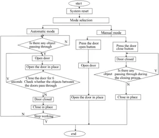
The basic functions realized by this design are as follows: 1) When there is no data connection with the PLC, the new file can be edited according to actual needs, the error location is checked, the program and system configuration are modified, and the program is stored in the hard disk of the PC. 2) Under the on-line communication, the software uploads and downloads data and programs, and can directly operate the PLC, such as editing programs and modifying in-structions. When writing a program is an error, the software can point out some of the errors entered. When writing a ladder diagram, when there is a program problem, the dialog window below can directly indicate the problem of the net-work program that has the problem, and the user can modify the program ac-cording to the prompt. 3) At the menu bar of the software, the user can use the response function module according to the prompt. 4) The user can modify the PLC configuration, communication settings, and work type, and can also moni-tor the operation of the PLC. The system flow is shown in Figure 3.
DOI: 10.4236/oalib.1105891 5 Open Access Library Journal
Figure 3. System flow chart.
the door opener I0.4 and enters the 8s timing. During the three sensors I0.6, I0.7, I1.0, if an object is detected, the timer T37 retimed. After the automatic door de-tects no object for 8 s, the PLC’s Q0.1, M0, V0 action, pass to the inverter a mo-tor reversal signal and low speed running signal, a total of 6s automatic door closing, if any object is closed when the automatic door is closed I1.0 detects that the automatic door stops closing and executes the automatic door opening pro-cedure. In the automatic closing, due to the fact that the object passes the fast factor, the automatic door uses a safety grating with a delay of only 0.2 s to pre-vent the object from being clamped.
There are two kinds of alarm conditions in the automatic door. The first one is the automatic door program. The automatic door appears to be operated ma-nually or automatically (Q0.0 or Q0.2) and closed (Q0.1 or Q0.3). The door will judge by the program, the M0.1 action will stop the whole automatic door con-trol system, the fault light Q1.1 will light up, remind the staff to come to check, after checking no problem, press the abnormal reset button I1.3 to make the au-tomatic The gate program is reset.
DOI: 10.4236/oalib.1105891 6 Open Access Library Journal
or not someone has changed the frequency of the inverter through the system.
Conflicts of Interest
The authors declare no conflicts of interest regarding the publication of this pa-per.
References
[1] Jiang, J.F. (2010) Siemens S7-200 PLC Engineering Application Technology Tutori-al. Mechanical Industry Press, Beijing.
[2] Xiang, X.H. (2010) Siemens S7 PLC Advanced Application Examples Explained. Mechanical Industry Press, Beijing.
[3] Zhao, J.B. (2011) The Example Explains the Siemens S7-200PLC from Entry to the Essence. Publishing House of Electronics Industry, Beijing, 21-30.
[4] Gao, H. (2011) PLC Sequential Control Design Method and Its Application. Hen-gyang Finance and Industry Vocational and Technical College, No. 4, 145-146. [5] Hu, Y.Y. (2017) PLC Automatic Door Working Principle. Suffolk University School
of Science and Technology, No. 16, 247-248.
[6] Tao, J. (2017) Automatic Sliding Door Design Based on PLC. Science and Technol-ogy Information, No. 19, 55-58.