Buckling of Discretely Stringer-Stiened
Composite Cylindrical Shells under Combined
Axial Compression and External Pressure
D. Poorveis1 and M.Z. Kabir
In this paper, the static buckling of especially orthotropic stringer-stiened composite cylindrical shells subjected to combined axial compression and external pressure is investigated, based on geometrical non-linear analysis with considering pre-buckling deformations. The kinematic relation of shells is based on the Donnell non-linear theory and First Order Shear Deformation (FOSD) is adopted for both shell and stieners. Displacements, rotations and interacting forces are expressed in terms of Fourier series expansions as independent approximate solution functions. Unknown coecients of shell and stringers are related by satisfying continuity conditions of displacements at their contact areas using Lagrange multipliers. The non-linear equilibrium equations are obtained using the Ritz method. The eects of sensitivity parameters, e.g., shell lay-ups, dierent numbers of stringers in the circumference, location of stieners (outside vs. inside) and the discrete versus smeared approach on interaction buckling curves are considered. Results indicate remarkable dierences between outside and inside stringer-stiened cylinder buckling loads and also illustrate the fundamental role of shell stacking sequences and stiened shell geometry on the applicability range of the smeared stiener approach.
INTRODUCTION
Stiened thin cylindrical shells subject to combined external pressure and axial compression are widely used in aerospace structures and the oshore-oil industry. Research on the buckling and post-buckling of stringer-stiened cylindrical shells in the past three decades have increased. In the context of experimental studies, various specimens with dierent shell and stringer geometry and boundary conditions were tested under axial compression by Weller and Singer [1]. Also, Singer and Abramovich [2] applied vibration tests to dene practical boundary conditions in stiened shells. Weller [3] studied the inuence of in-plane boundary conditions on the critical load of axially compressed simply supported stringer-stiened cylin-drical shells. Sheinman, Shaw and Simitses [4] used a
1. Department of Civil and Environmental Engineering, Amirkabir University of Technology, Tehran, I.R. Iran.
*. Corresponding Author, Department of Civil and Envi-ronmental Engineering, Amirkabir University of Tech-nology, Tehran, I.R. Iran.
smeared stiener technique for orthogonally stiened laminated cylinders. Bushnell [5] developed PANDA, an interactive program, to design minimum weight sti-ened cylindrical panel under combined in-plane loads. Discrete analysis of orthogonally stiened composite cylindrical shells, subjected to combinations of uniform internal pressure, constant temperature changes and axial load, were investigated by Wang and Hsu [6]. Abramowitz, Weller and Singer [7] appraised the eect of a sequence of combined loading on the buckling of stiened shells. They showed that order of loading does not aect the buckling loads. Ji and Yen [8] studied the buckling of orthogonally stiened cylinders. They assumed that stringers can be closely spaced and treated by a smeared model but that part of a shell stiened with rings was treated as a discrete shell element. A singular perturbation technique was used by Shen and his co-workers [9,10] to investigate the buckling and post-buckling behavior of perfect and imperfect stiened cylinders. Dawe and Wang [11] applied a nite strip method to assess the post-buckling response of stiened composite panels. The strip ele-ment with dierent nodal lines, was used for modeling
longitudinal stieners. The buckling of axially stiened conical shells under axial compression was studied by Spagnoli [12]. Dierent modes of instability, in particular, local shell and stringer buckling modes and a global buckling mode through a linear eigenvalue nite element analysis were investigated. Haixu [13] derived equilibrium equations for a double cylindri-cal shell stiened longitudinally and transversely and subjected to uniform hydrostatic external pressure by using an adjacent equilibrium method. He calculated the theoretically critical pressures of panel buckling and interframe shell buckling. The dynamic buckling of cylindrical stringer-stiened shells was explored both numerically and experimentally by Yae and Abramovich [14]. They used the ADINA nite element code to simulate the static and dynamic buckling loads of the shells.
The current paper investigates the buckling of discretely stringer-stiened laminated cylindrical shells subject to combined external pressure and axial com-pression. The boundary conditions are assumed to be classical and simply supported. Initial imperfection is in the form of a buckling mode and its amplitude is taken as small so as not to aect the buckling load. The critical load is calculated by controlling the determinant sign of the tangent stiness matrix. Various stringer-stiened composite cylinders, diering in the number of stieners, laminate architectures and location of stringer (outside vs. inside), are analyzed to estimate the range of applicability of the smeared stiener model. Interaction buckling curves are plotted for dierent cases and, to compare the results, more concentration is put on these curves.
THEORY
For the discrete model, displacements, rotations and interaction forces are expressed in terms of Fourier series expansions as independent approximate solution functions. These functions are related by continu-ity conditions of displacement between the shell and stieners at their contact area by Lagrange multiplier coecients. The equilibrium equations are obtained using the Ritz method. The linearized equations can be solved using iterative Newton-Raphson and arc-length methods [15]. In the smeared stiener approach, shell rigidities are modied based on material and geometrical properties and the spacing of stringers. Then, analysis, such as that of an unstiened shell, is carried out.
SHELLAND STIFFENERGEOMETRY
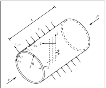
The conguration of a shell with global coordinates is sketched in Figure 1. The principal material directions are specied as 1 and 2. The global coordinate system
Figure 1.
Cylindrical shell with coordinate system, key dimensions and loading.x, and z, displacement components U, V, W and rotations x and are also shown in Figure 1. In
the same gure, the lateral pressure,q, the axial force,
P, the length, L, the thickness, h, and the radius of curvature of middle surface,R, are also shown. is the angle between the principal material axis, 1, and the
x-axis of the shell. Also, deviation of the ber direction in the stringer is measured, with respect to the longi-tudinal axis. Figure 2 shows the stringer coordinate axesx,andzin the longitudinal, circumferential and radial directions, respectively, which are located at its centroid and which are parallel to those of the shell. Displacements and rotations of the stiener shown in the mentioned gure are also measured at the centroid. Interacting forces, as a result of the contact stresses, are depicted in this gure.
Figure 2.
Stringer coordinate system and interacting forces between shell and stiener.DISPLACEMENTS ANDROTATIONS
The displacements of an arbitrary point of the cylin-drical shell is expressed as:
U(x;;z) =U(x;) +zx(x;);
V(x;;z) =V(x;) +z(x;);
W(x;;z) =W(x;); (1)
where U(x;), V(x;) and W(x;) are displacements of the mid-surface of the shell in axial, circumferential and radial directions, respectively, and x(x;) and
(x;) are the rotations of the normal vector to the
surface. Similarly, the stringer displacements in x,
andz directions are dened as [16]:
Us(x;;z) =Us(x) +zs(x) R0zs(x) !(;z)s; Vs(x;z) =Vs(x) +zxs;
Ws(x;) =Ws(x) R0xs; (2) where Us, Vs and Ws are stiener centroid
displace-ments andxs,sandzsare rotations of the stiener
about the mentioned axes, respectively. !(;z) is a warping function of the stiener cross section, R0is the distance between the stringer centroid and the center of the cylinder andsis the unknown warping coecient.
Neglecting the shear strain in warping,sbecomes:
s= @@x :xs (3)
STRAIN-DISPLACEMENT RELATIONSHIPS
The strain-displacement relationships at an arbitrary point of the shell thickness can be expressed as follows:
ex="x+zx; e="+z; ex=x+zx;
(4) where strains of mid-plane and curvatures, based on Donnell and the rst order shear deformation theories and initial imperfection ( ^W), are as follows:
"x=@U@x + 12
@W
@x
2
+ @@xW^ ! @W @x ; "= 1R@V@+WR + 12R2
@W
@
2 + 1R2
@W^ @ ! @W @ ;
x= 1R@U@ +@V@x + 1R
@W @x @W @ + 1R @W @x
@W^ @
!
+ 1R @@xW^ ! @W @ ; x= @@x ; x = 1R@@ ; x= 1R@@x +@@x ;
xz=x+@W@x ; z=+ 1R
@W
@
: (5)
Similarly, for stringer, the non-zero strains are:
esxx= @U@xs+ 12 @Ws @x 2 + 12 @Vs @x 2 + @@xW^s
! @Ws @x ; sx= 1R
0 @Us
@ +@V@x ; s sxz= @U@zz +@W@x :s (6)
In these relations, ^Ws is the initial imperfection of
the stringer, which is obtained by substitution of the stringer position ( = s) in the shell initial
imper-fection ( ^W). Due to the small rotations of stieners, only displacement components are retained in the non-linear terms of strain. Using Equations 2, the strains are expressed in terms of displacements and rotations at the centroid.
CONSTITUTIVE EQUATIONS
The stress-strain relationship for the shell is expressed as:
fg= [C]f"g; (7)
where [C] is the generalized material rigidity matrix. The vector of stress resultants is dened as:
fg= [Nx;N;Nx;Mx;M;Mx;Qx;Q]T; (8) N, M and Q are in-plane forces, moments and out of plane shear components in unit length, respectively. The generalized strain vector,f"g, is:
f"g= ["x;";x;x;;x;xz;z]T; (9) where"x,"andxare mid-surface strains andxand
are bending curvatures in x z and z planes,
respectively. xis in-plane twist curvature andxzand
z represent transverse shear strains. [C] matrix is:
[C] = 2 6 6 4
[A] [B] 0 0 [B] [D] 0 0
0 0 A44 0
0 0 0 A55
3 7 7
whereAij are membrane rigidities,Bij are
membrane-bending coupling terms,Dij are bending rigidities and
transverse shear rigiditiesA44 andA55 are dened as: (Aij;Bij;Dij) =
Z
h (1;z;z
2)Q
ijdz;
A44= Z
h Q
44dz; A 55=
Z
h Q
55dz; (11)
whereQijis the transformed reduced stiness [17]. The stress components corresponding to non-zero strains for the stiener are sxx, sx and sxz. Stress-strain relations at a generic point in the stringer are expressed as: 8 < : sxx sx sxz 9 = ; = 2 4
Qs11 Q
s
16 0 Qs16 Q
s
66 0 0 0 Qs44
3 5 8 < : esxx sx sxz 9 = ; ; (12)
where Qs11, Q
s
16, Q
s
44 and Q
s
66 are the transformed reduced stinesses for the stringer. In the case of orthotropic laminate, Qs16 is zero. Integrating Equa-tion 12 over the stiener cross-secEqua-tion, the following constitutive equation is obtained.
fNxs;Ms;Mzs;M!s;Tss;Vs;VzsgT =
[Es]f"xs;s;zs;!s;ss;s;zsgT; (13) where Nxs, Ms, Mzs, M!s and Tss are axial force,
bending moments about axes and z, bimoment and uniform torsion, respectively. Also Vs and Vzs are
shear forces in and z directions. The symmetric (77) matrix, [Es], is the elasticity tensor, which represents the material and geometrical properties of the stringer. Details of the deriving elements of [Es]
for stiener with an arbitrary thin-walled cross-section and with general orthotropic material can be found in [16,18]. The generalized strain vector, according to displacements and rotations of the stringer centroid, are:
"xs= @U@xs+ 12
@Ws @x 2 + 12 @Vs @x 2 + @@xW^s
! @Ws @x ;
s=@@x ; s zs= @@x ; zs !s= @
2
xs
@x2 ; ss =@@x ; xs s=
@Vs
@x zs
; zs=
@Ws
@x +s
; (14)
where, "xs is the axial stretch, s, zs and !s the
bending and warping curvatures, respectively, ands
and zs are transverse shear strains due to bending.
Also, ss represents the torsional curvature of the
stringer.
FOURIER APPROXIMATIONS
For classical simply supported end conditions, the double expansions of the Fourier series for shell dis-placements and rotations are:
U(x;) = (x L=2)Ux0 +XM
m=1
N
X
n=0
Umn cos(mx) cos(n);
V(x;) = XM
m=1
N
X
n=1
Vmn sin(mx) sin(n);
W(x;) = XM
m=1
N
X
n=0
Wmn sin(mx) cos(n);
x(x;) = XM
m=1
N
X
n=0
xmn cos(mx) cos(n);
(x;) = XM
m=1
N
X
n=1
mn sin(mx) sin(n); (15)
in whichm=m=LandMandN are the upper limit
of integer numbersmandn. The unknown coecients,
Ux0,Umn,Vmn,Wmn,xmnandmn, are obtained in each incremental step. The displacement and rotation functions of stieners are assumed as follows:
Us(x) = (x L=2)Us0+
M
X
m=1
Usmcos(mx);
Vs(x) = XM
m=1
Vsmsin(mx);
Ws(x) = XM
m=1
Wsmsin(mx);
xs(x) = XM
m=1
xsmsin(mx);
s(x) = XM
m=0
smcos(mx);
zs(x) = XM
m=1
where Us0, Usm, Vsm, Wsm, xsm, sm and zsm are the stringer unknown coecient. In Equations 15 and 16, Ux0 and Us0 are required to ensure correct distribution of stresses in the shell and stringers for the pre-buckling state. The existing stresses at the interfacial area between cylindrical shell and stringer are shown in Figure 2, in terms of forces and moments per unit length, and their Fourier expansions are as follows:
xs(x) = XM
m=1
xsmcos(mx);
s(x) = XM
m=1
smsin(mx);
zs(x) = XM
m=1
zsmsin(mx);
xs(x) = XM
m=1
xsmsin(mx);
zs(x) = XM
m=0
zsmcos(mx); (17)
wherexsm,sm,zsm, xsmand zsmare unknown
coecients. The continuity of displacements at the interface is required:
gxsj =U(x;j) +h2x(x;j)
[Usj(x) +esjsj(x) !0jsj(x)] = 0; gsj=V(x;j) +h2(x;j)
[Vsj(x) +esjxsj(x)] = 0;
gzsj=W(x;j) Wsj(x) = 0;
Gxsj =@W@ (x;j) + (R+h=2)xsj(x) = 0;
Gzsj=@U@(x;j) +h2@@x(x;j)
+ [(R+h=2)zsj(x) +!1jsj(x)] = 0: (18) The subscript,j, is related to thejth stringer and!0j and!1j are warping constants of the top ange, which is in contact with the shell. Also, esj is the distance
from the centroid of the jth stringer to the contact surface. The variation limit ofx is 0xL.
!s(;esj) =!0j+!1j: (19)
NON-LINEAR ANALYSIS(DISCRETE MODEL)
The equilibrium equations of stiened cylinders are obtained by combining the internal virtual work of shells and stieners, external virtual work due to applied loads and the virtual work of interaction forces. The non-linear equations are solved by the Newton-Raphson method. The internal virtual work of the cylindrical shell is:
Wint
sh =
ZZ
S
h
Nx"x+N"+Nxx+Mxx
+M+Mxx+Qxxz+Qz
i dS:
(20) Also, the internal virtual work of longitudinal stieners is:
Wint
s = L
Z 0
[Nxs"xs+Mss+Mzszs+M!s!s
+Tssss+Vss+Vzszs]dx:
(21) The external virtual work, due to axial compression and external pressure, is:
Wext
sh = P
2 Z 0
[U(1;) U(0;)]Rd qDZ
S WdS:(22)
In which P is the axial force per unit length of the cylinder circumference and qD is the radial dead
pressure. For hydrostatic pressure, P is related to
qD(P =RqD=2). In the case of live external pressure,
which is displacement dependent [19], the second term of Equation 22 is modied as:
qLZ
S
"
W+ 1R(V V+WW)+W @U
@x+ 1R@V@
+W @U
@x + 1R@V@
# dS:
(23) The virtual work of interacting forces between shell and stieners, with respect to the continuity relations in Equations 18, is expressed as:
W=X
j L
Z 0
[xsjgxsj+zsjgzsj+sjgsj
In whichP
jexhibits summation over the total number
of stringers. The total virtual work of the system is:
Wint
sh +Wint
s +W Wshext= 0: (25)
Linearization and discretization of Equation 25 leads to:
2 4
Ksh+KL 0 Kshs
Ks Kshs
Sym. 0 3 5 8 < : Ush Us s 9 = ; = 8 < : Rsh Rs R 9 = ; = 8 < : Fext
sh Fint
sh Fshs
Fint
s Fss
Fs
9 = ;
: (26)
In which Ksh and Ks are shell and stringer tangent
stiness matrices, respectively. KL is the load stiness
matrix, which reects live external pressure eects and Kshs and Kss are stiness submatrices derived
from interaction forces virtual work. Also, Ush and
Us are shell and stiener incremental displacement
vectors and sdenes incremental interaction forces.
Residual forces obtained from Equations 20 to 25 are in the right hand side of Equation 26. To solve Equa-tion 26, non-linear in shell and stiener displacements, the coecient matrix, [K], is decomposed into the multiplication of three matrices, as follows:
[K] = [L][D][LT]; (27)
where [L] and [D] are lower triangular and diago-nal matrices, respectively. The update procedure to determine the generalized incremental displacement vector, U (Equation 26), is based on the full Newton method. In this method, tangent stiness matrix, [K], and residual vector,R, are modied at each step and iteration. An error function, dened as UTR
(residual work), is used to check the convergence against a prescribed tolerance. Also, the buckling load is calculated by controlling the determinant sign of [K](det[K] =Q
i Dii).
NON-LINEAR ANALYSIS(SMEARED
MODEL)
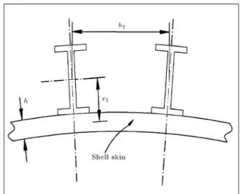
Shell rigidities are modied based on material prop-erties, cross-sectional dimensions and spacing of stringers. The stringer-stiened shell rigidities, accord-ing to Figure 3 and [9], are:
[A] = 2 4
A11 A12 0 A12 A22 0
0 0 A66
3 5+
2 4
E1A1=b1 0 0
0 0 0
0 0 0
3 5; [B] =
2 4
B11 B12 0 B12 B22 0
0 0 B66
3 5+
2 4
E1A1e1=b1 0 0
0 0 0
0 0 0
3 5;
Figure 3.
Geometry of a stringer-stiened cylindrical shell.[D] = 2 4
D11 D12 0 D12 D22 0
0 0 D66
3 5 +
2 4
E1(I1+A1e 2 1)=b
1 0 0
0 0 0
0 0 (G1J1=b1)=4 3
5; (28) whereE1A1andG1J1are the extensional and torsional rigidities of the stringer in the longitudinal direction, respectively, I1 is the moment of inertia of the beam stiener cross-section about its centroidal axis ande1 is the stringer eccentricities (positive outside). The analysis continues as that of an un-stiened shell, so, by eliminatingWint
s and W from Equation 25, one
has:
Wint
sh Wext
sh = 0: (29)
NUMERICAL RESULTS AND
DISCUSSIONS
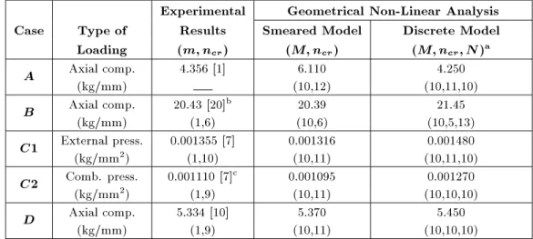
The described analysis is used as a base for the development of a computer program. In the literature, most of the experimental and analytical results of stringer-stiened shells buckling load are restricted to those of an isotropic material and a smeared stiener approach. The rst numerical example, which serves as verication for the current analysis, including several isotropic outside stringer-stiened cylinders under axial compression, external pressure and a combination of both [1,7,10,20], are analyzed by the current discrete and smeared geometrical non-linear methods. Another numerical study is designed to compare the results of miscellaneous stringer-stiened cylindrical shells, dierent in shell lay-ups, stiener geometry, stringer spacing and method of analysis (discrete vs. smeared). The results are presented in the form of interaction buckling curves.
Table 1.
Outside stringer-stiened cylindrical shells dimensions (E= 7500 kg/mm 2,= 0:3).
Case
(mm)
L
(mm)
R
(mm)
h
n
s(
A
1=b
1h
) (
e
1=h
) (
I
1=bh
3
) (
G
1
J
1=bD
)
A
78.618 120.56 0.204 56 0.717 3.670 2.400 19.839B
965.20 242.57 0.719 60 1.028 5.830 9.629 16.912C
200.00 120.27 0.249 84 0.666 4.030 2.770 7.505D
130.00 120.10 0.254 85 0.590 3.420 1.680 6.563Table 2.
Comparison of experimental and analytical buckling load for various stringer-stiened cylindrical shells.Experimental
Geometrical Non-Linear Analysis
Case
Type of
Results
Smeared Model
Discrete Model
Loading
(
m;n
cr)
(
M;n
cr)
(
M;n
cr;N
)
aA
Axial comp.(kg/mm) 4.356 [1] (10,12)6.110 (10,11,10)4.250B
Axial comp.(kg/mm) 20.43 [20]b(1,6) (10,6)20.39 (10,5,13)21.45
C
1
External press.(kg/mm2)0.001355 [7]
(1,10) 0.001316(10,11) (10,11,10)0.001480
C
2
Comb. press.(kg/mm2)0.001110 [7]c
(1,9) 0.001095(10,11) (10,10,10)0.001270
D
Axial comp.(kg/mm) 5.334 [10](1,9) (10,11)5.370 (10,10,10)5.450a:M andNrepresent number of non-zero terms in the axial and circumferential direction, respectively. b: This result is related to smeared linear theory.
c: q
cr in the presence of constant axial compression (
P= 1:0587 kg/mm).
ISOTROPIC STIFFENEDCYLINDERS
Shell and stringer geometries of four isotropic outside stringer-stiened cylindrical shells with a various num-ber of stringers are shown in Table 1. For all specimens,
E = 7500 kg/mm2, = 0:3 and boundary conditions are classical simply supported. Experimental results for dierent loading types, along with the current analysis buckling loads and their corresponding modes, are indicated in Table 2. Due to using several terms to approximate displacements and rotations in the circumference, discrete model buckling load predictions are in good agreement with those of experimental results. Although, in cases B, C and D, dierences in the results of discrete and smeared geometrical non-linear analyses are negligible, in case A, the variation is signicant. In this case,A, local eect (panel insta-bility) is the dominant factor in discrepancy between the results of smeared analysis and those of discrete analysis and experiment.
INTERACTION BUCKLING CURVES
Extensive studies exploring the eects of stringer discreteness, shell stacking sequences and location of
stiener (inside vs. outside) on interaction buckling curves are carried out. According to Figure 1, the dimensions of the assumed shell are;R= 100 mm,L= 100 mm andh= 1 mm. Also, referring to Figure 3, for stieners,A1=b1h= 0:232,e1= 3:0 mm (outside) and e1= 3:0 mm (inside). In all cases, the stringer height is constant but its width varies. Shell and stiener material properties areE11= 140 KN/mm
2,E
22= 9:1 KN/mm2, G
12 = 4:3 KN/mm 2, G
13 = 4:7 KN/mm 2, G23 = 5:9 KN/mm
2 and
12 = 0:3. Stringer lay-up is taken as constant, (0), and shell stacking sequences vary according to the following arrangements: (0)8, (90)8, (0=90=0=90)s, (45= 45)4T, (75= 75)4T.
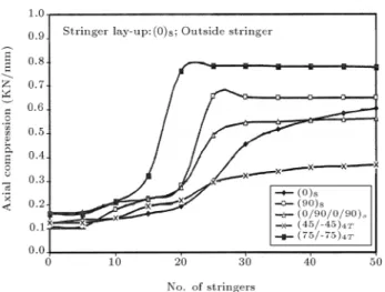
Figure 4 illustrates the convergence of an axial buckling load versus an increase in number of stringers in the circumference for the above mentioned shell ar-chitecture of outside stringer-stiened composite shells. Axial critical loads for un-stiened shells are also indicated in this gure. For all shell lay-ups except (0)8, despite dierences in buckling loads, the trends of convergence are similar and local instability in the case of 50 stringers becomes negligible. In the case of shell arrangement (0)8, due to lack of stiening in the circumferential direction, even for 50 stringers or more, panel instability plays a fundamental role in the
Figure 4.
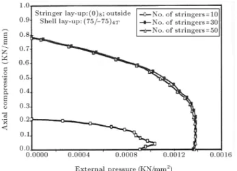
Convergence of axial buckling compression of various stringer-stiened cylinders with increasing number of stringers.overall buckling load. It is also observed, with respect to Figure 4, that there is a considerable change in the load carrying capacity of stiened shells when the number of stringers increases from 10 to 30. Figure 5 shows interaction buckling curves derived based on a smeared stiener approach for various outside stringer-stiened cylinders. Stiened shells with an anti-symmetric lay-up, (75= 75)4T, exhibit a more stable area. Similar curves, according to discrete analysis for inside and outside stringer-stiened shells, are plotted in Figures 6 and 7. Again, shell lay-up, (75= 75)4T, is suitable for outside stiening but, in an inside case, this preference mainly belongs to a (0=90=0=90)s
arrangement. Figures 8 to 10 dictate that for all shell lay-ups and both discrete and smeared analysis, outside stiening produces substantially more strength to buckling than that of an inside one. Figures 11 to 13, indicate inuences of stringer discreteness with a change in the number of stringers, along with a
Figure 5.
Comparison of dierent outside stringer-stiened composite cylindrical shells for interaction buckling curve (smeared model).Figure 6.
Eect of various shell lay-ups on interaction buckling curve of outside stringer-stiened cylinder (discrete model).Figure 7.
Eect of various shell lay-ups on interaction buckling curve of inside stringer-stiened cylinder (discrete model).Figure 8.
Eect of stringer location (inside vs. outside) and stringer modeling (smeared vs. discrete) oninteraction buckling curve of stiened shells (shell lay-up: (90)8).
Figure 9.
Eect of stringer location (inside vs. outside) and stringer modeling (smeared vs. discrete) oninteraction buckling curve of stiened shells (shell lay-up: (0=90=0=90)
s).
Figure 10.
Eect of stringer location (inside vs. outside) and stringer modeling (smeared vs. discrete) oninteraction buckling curve of stiened shells (shell lay-up: (75= 75)
4T).
variation of shell architecture for outside stringer-stiened shells. Variation of the interaction buckling curve for a 10-stringer case, relative to the other two cases (30 and 50) is noticeable. Figure 11 shows some increase in the external pressure buckling strength in the presence of low axial compression (P=Pcr < 0:3).
This eect can be explained by considering two factors; rst, axial load eccentricity, which produces initial positive circumferential strain,"(axial compression is
applied through the shell middle surface) and, second, the large ratio of A22=A12 in the case of shell lay-up (90)8. These parameters aect the circumferential force,N(N=A12"x+A22"), which, in turn, releases some compression force produced by applied external pressure. For other shell arrangements, despite existing load eccentricity, the stiness ratio,A22=A12, is not so high to substantially reduce circumferential
compres-Figure 11.
Inuence of number of stringers on the interaction buckling curve of discretely stringer-stiened cylindrical shells (shell lay-up: (90)8).Figure 12.
Inuence of number of stringers on the interaction buckling curve of discretely stringer- stiened cylindrical shells (shell lay-up: (0=90=0=90)s).
Figure 13.
Inuence of number of stringers on the interaction buckling curve of discretely stringer-stiened cylindrical shells (shell lay-up: (75= 75)Figure 14.
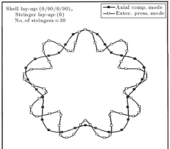
The variation limits of outsidestringer-stiened shell circumferential buckling mode for shell lay-up (0=90=0=90)
s.
sion. Also, with an increase in the number of stieners (Nstr: 30) and a dominating global buckling mode, buckling strength to combined loading noticeably in-creases and the mentioned eect dein-creases.
Variation of the circumferential wave number,
ncr, is equivalent to the change, in a tangent direction,
of the interaction buckling curve and, consequently, the more alteration of ncr, the more non-linearity of
the buckling curve. Figure 14 indicates the lower and upper bounds of the circumferential mode for outside stiening with shell lay-up (0=90=0=90)swhose
wave number varies from ncr = 5 (axial compression
buckling mode) toncr= 9 (external pressure buckling
mode). These limits for shell arrangements (90)8 and (75= 75)4T are (5,8) and (6,9), respectively. For inside stiening, these numbers are restricted to ncr = 6 for
shell lay-up (75= 75)4T,ncr= 5;6 in the case of shell lay-up (90)8 and ncr = 7;8 for symmetric cross-ply arrangement, (0=90=0=90)s(Figures 8 to 10).
CONCLUSIONS
Discrete and smeared as two approaches in geomet-rical non-linear analyses have been implemented to study isotropic and orthotropic equally spaced stringer-stiened cylindrical shells subject to combined axial compression and external pressure. On the basis of the case studies, the following conclusions may be drawn: 1. For isotropic outside stringer-stiened cylinders,
the discrete model predicts the axial buckling load more accurately than those of external and combined pressures and the maximum deviation from an experimental axial buckling load is less than 5 percent. Also, in all loading cases, the circumferential wave number,ncr, obtained, based
on smeared model analysis, is greater than that of a discrete one;
2. For outside stringer-stiened composite cylindrical shells, shell stacking sequence (75= 75)4T encloses a more stable area, while shell lay-up (0=90=0=90)s
exhibits less stability against combined axial com-pression and external pressure. In inside stiening cases, arrangement (0=90=0=90)sencircles a greater
stable zone than those of lay-ups (90)8 and (75= 75)4T;
3. For all shell stacking sequences and both models of stringer (smeared vs. discrete), outside stiening shows more stability against combined loading than that of inside stiening, especially at a high ratio of axial compression to external pressure. Also, due to a wide range of mode variation, outside stringer-stiened cylinders involve a non-linear form, while inside-stiened shells take a nearly linear appear-ance;
4. Apart from shell stacking sequences, in outside sti-ening cases, interaction buckling curves obtained, based on a smeared model analysis, encompass those curves plotted according to a discrete model analysis. The trend for the inside stiening case is opposite;
5. In the case of outside stiening, the number of stringers in the circumference play a fundamental role in estimating critical load and the interacting buckling curve. For 10 stringers, panel instability (shell skin buckling between stieners) considerably aects buckling load, while, in the cases of 30 and 50 stringers, local eects diminish and the contribution of stieners in the buckling response increases. REFERENCES
1. Weller, T. and Singer, J. \Experimental studies on the buckling under axial compression integrally stringer-stiened circular cylindrical shells",Journal of Applied Mechanics,
44
(4), pp 721-730 (1977).2. Singer, J. and Abramovich, H. \Vibration techniques for denition of practical boundary conditions in sti-ened shells",AIAA Journal,
17
(7), pp 762-769 (1979). 3. Weller, T. \Combined stiening and in-plane boundary conditions eects on the buckling of circular cylindrical stiened shells", Comput. & Struct.,9
(1), pp 1-16(1978).4. Sheinman, I., Shaw, D. and Simitses, G.J. \Nonlinear analysis of axially loaded laminated cylindrical shells",
Comput.&Struct.,
16
, pp 131-137 (1983).5. Bushnell, D. \PANDA- interactive program for mini-mum weight design of stiened cylindrical panels and shells",Comput. &Struct.,
16
, pp 167-185 (1983). 6. Wang, J.T.S. and Hsu, T.M. \Discrete analysis ofstiened composite cylindrical shells",AIAA Journal,
7. Abramovich, H., Weller, T. and Singer, J. \Eect of sequence of combined loading on buckling of sti-ened shells",Experimental Mechanics,
28
(1), pp 1-13 (1988).8. Ji, Z.Y. and Yeh, K.Y. \General solution for nonlinear buckling of nonhomogeneous axial symmetric ring-and stringer-stiened cylindrical shells", Comput. &
Struct.,
34
(4), pp 585-591 (1990).9. Shen, H.S. \Post-buckling analysis of imperfect sti-ened laminated cylindrical shells under combined ex-ternal pressure and axial compression", Comput. &
Struct.,
63
(2), pp 335-348 (1997).10. Shen, H.S., Zhou, P. and Chen, T.Y. \Postbuckling analysis of stiened cylindrical shells under combined external pressure and axial compression",Thin-Walled Structures,
15
, pp 43-63 (1993)11. Dawe, D.J. and Wang, S. \Postbuckling analysis of composite laminated panels", AIAA Journal,
38
(11), pp 2160-2170 (2000)12. Spagnoli, A. \Dierent buckling modes in axially stiened conical shells", Engineering Structures,
23
, pp 957-965 (2001).13. Haixu, D. \Strength and stability of double cylindri-cal shell structure subjected to hydrostatic external pressure-II: Stability", Marine Structures,
16
(5), pp 397-415 (2003).14. Yae, R. and Abramovich, H. \Dynamic buckling of cylindrical stringer stiened shells", Comput. &
Struct.,
81
(8-11), pp 1031-1039 (2003).15. Bonet, J. and Wood, R.D., Nonlinear Continuum Mechanics for Finite Element Analysis, Cambridge University Press, Cambridge, UK (1997).
16. Rastogi, N. \Load transfer in the stiener-to-skin joints of a pressurized fuselage", Doctoral Dissertation, Department of Aerospace and Ocean Engineering, Virginia Polytechnic Institute and State University, Blacksburg, Virginia, USA (1995).
17. Jones, R.M.,Mechanics of Composite Material, Hemi-sphere, Washington D.C., USA (1975).
18. Woodson, M.B. \Optimal design of composite fuselage frames for crashworthiness", Doctoral Dissertation, Department of Aerospace and Ocean Engineering, Virginia Polytechnic Institute and State University. Blacksburg, Virginia, USA (1994).
19. Schweizerhof, K. and Ramm, E. \Displacement depen-dent pressure load in nonlinear nite element analysis",
Comput.&Struct.,
18
(6), pp 1099-1114 (1984). 20. Brush, D.O. and Almorth, B.O., Buckling of Bars,Plates, and Shells, McGraw-Hill, New York, USA (1975).