ISSN: 2252-8938, DOI: 10.11591/ijai.v6.i2.pp79-90 79
Improved Sensorless Direct Torque Control of Induction Motor
Using Fuzzy Logic and Neural Network Based Duty Ratio
Controller
Sudheer H1, Kodad SF2, Sarvesh B3 1
FST-IFHE, Hyderbad
2
Department of Electrical Engineering, PES Inst. Of Tech. & Management
3
Department of Electrical Engineering, JNTU Anantapur
Article Info ABSTRACT
Article history: Received Feb 12, 2017 Revised Apr 16, 2017 Accepted May 25, 2017
This paper presents improvements in Direct Torque control of an induction motor using Fuzzy logic with Fuzzy logic and neural network based duty ratio controller. The conventional DTC (CDTC) of induction motor suffers from major drawbacks like high torque and flux ripples and poor transient response. Torque and flux ripples are reduced by replacing hysteresis controller and switching table with Fuzzy logic switching controller (FDTC). In FDTC the selected switching vector is applied for the complete switching time period. The FDTC steady state performance can be improved by using duty ratio controller, the selected switching vector is applied only for the time determined by the duty ratio (δ) and for the remaining time period zero switching vector is applied. The selection of duty ratio using Fuzzy logic and neural networks is projected in this paper. The effectiveness proposed methods are evaluated using simulation by Matlab/Simulink.
Keyword:
Direct torque control (DTC) Neural network (NN) Fuzzy logic switching controller (FLSC) Induction motor (IM)
Copyright © 2017 Institute of Advanced Engineering and Science. All rights reserved.
Corresponding Author: Sudheer H,
JNTU Anantapur,
Faculty of Science and Technology, IFHE, Hyderabad, Telangana, India.
Email: [email protected], [email protected]
1. INTRODUCTION
Direct Torque and Flux Control of induction motor popularly known as DTC (Direct Torque control) was introduced by Takahashi and Naguchi for quick response and high efficiency of induction motor [1-2]. Over the years DTC emerged as an alternative to FOC (Field Oriented Control) due to advantages like absence of co-ordinate transformations, current loops and separate voltage modulation block [3-4]. However, conventional DTC (CDTC) suffers from major drawbacks like high torque and flux ripples predominantly at a) low speed and start-up [5-7] b) Variable switching frequency varies according to motor speed, hysteresis bans in torque and flux loops [5-6] c) current and torque distortion when sector changes [7]. In order to overcome the disadvantages several techniques are developed by researches during like direct self-control, DTC with SVM and DTC-SVM with Neuro-Fuzzy logic controllers as given in [8]. Improved CDTC with multi-level inverters, matrix inverters and sensorless drive are proposed in [9-11]. The application of AI techniques like Fuzzy logic, Neural Networks, Neuro-Fuzzy in Direct Torque control gained great attention in late years. The execution of the CDTC switching table with Fuzzy is given in [8], [12-15] which results in reduction of torque and flux ripples. The implementation of DTC with Neuro Fuzzy controller is given by [7], [16] and using ANN is given in [17-19]. Torque ripple reduction in DTC using simple duty ratio controller is first proposed in [20]. The duty ratio algorithm proposed by [21] demonstrates that active voltage vector is given only for a part of sampling period while zero voltage vector is applied for remaining time period results in torque ripple reduction. Implementation of Fuzzy logic duty ratio controller help to
determine the optimal duty ratio to meet the torque and flux command [22-24]. In this paper CDTC first improved using Fuzzy logic based switching controller called Fuzzy DTC (FDTC). As Explained in the [25-27] speed sensor elimination was important in the industry. The Sensorless control results in lower cost, reduced hardware complexity. The current based Model Reference adaptive system (MRAS) proposed by Jakub Vonkomer et.al. [27] For a wide speed range of operation is employed in this paper for estimation of motor speed. Thus many researchers improved CDTC using Fuzzy logic or Duty ratio controller. In this paper the combination of both FDTC with ANN and Fuzzy based duty ratio controller for Sensorless direct torque control of induction motor is proposed. So based on literature the CDTC is first improved by a fuzzy logic controller (FLC) which employs 180 fuzzy rule base. The Switching vector of the Voltage Source Inverter (VSI) is chosen based on Fuzzy logic, which is tuned according range of flux and torque errors. The concept of duty ratio is introduced to reduce torque and flux ripple. The duty ratio is developed based on two AI techniques Fuzzy logic and Neural Networks. The speed and torque of the induction motor are estimated based current based adaptive estimator scheme as suggested in [27]. The performance of FDTC with Fuzzy duty ratio (FDR) and Neural Networks based duty ratio (NNDR) is assessed based on simulation results using Matlab/Simulink Software. Simulation results indicate that there is considerable reduction in torque and flux ripples using FDTC with Fuzzy or NN based duty ratio controllers. In both FDTC with Fuzzy DRC and NN DRC the speed of induction motor tracks the reference speed without any peak over shoots as in the case of CDTC. The stator current drawn by proposing schemes contains fewer harmonic and more sinusoidal waveforms compared to CDTC.
2. CONVENTIONAL DIRECT TORQUE CONTROL (CDTC)
The Induction motor model referred to the stationary reference frame (α, β) is developed in Simulink based on the state variable approach given the following equations. The model described by sudheer et.al. in [5], [31] is used to develop Simulink model of Indcution motor.
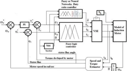
The DTC speed control of induction motor is utilized for high execution and quick torque response applications. In DTC Torque and Flux of induction motor can be independently controlled by selecting the optimal switching vector of inverter based torque and flux errors [1], [3]. The selection of inverter switching vector is done using classical switching table so as to restrict the torque and flux with in the hysteresis band thereby enabling fast transient response of the drive. The optimal selection of switching vector depends upon the stator flux position in space vector, torque and flux error. The challenges in DTC are an exact estimation of torque and flux parameters and switching table. Figure. 1 shows a block diagram of conventional DTC (CDTC) with current based adaptive Torque and Flux observer. The induction motor is fed by Voltage Source Inverter (VSI). Based on the stator currents ia, ib and rotor position the flux, torque and speed of the induction motor are estimated. The estimator diagram is shown in Figure 2. The Speed error is given to the discrete PI Controller of KP = 2 and KI = 300. The output of PI controller is limited using saturator Te* = +/- 8 N-m.
The estimated torque Te is compared with reference values generates a torque error (et) which is processed through three level hysteresis comparator in order to limit the torque error within hysteresis bands. The reference flux of the motor is estimated based on motor parameters given by:
Figure 2. Block diagram of Speed, Torque and Flux Estimator
√
(1)
The estimated flux is compared with reference flux generates flux error (eφ) which is processed through Two level hysteresis comparator. Based on the stator flux angle position the flux plane is divided into six sectors. If the stator flux angle between -300 to +300 is sector 1, +300 to +900 is sector 2. The digitalised outputs on it, eφ and Sector (S (n)) are given to a switching table given by Table 1., which selects the optimal switching state so, Sb, Sc. For example, if stator flux lies in sector 1, eT is positive and eφ is Positive then the motor has to accelerate to reduce the artquickly vector V2 is applied which rotates the flux in clockwise direction. If stator flux lies in sector 1, eT is negative and eφ is positive, then the motor has to decelerate vector V6 is applied which rotates the flux in anti-clockwise direction. If eT is zero switching vector V7 or V0 is applied. The switching sector is selected based present sector, flux error and torque error. The stator flux magnitude can be controlled by selecting one of the available voltage vectors that will move the flux in the desired direction [15].
Table 1. Switching Table of CDTC Sector
I II III IV V VI
Torque Flux
T=0 F=0 V5 V6 V1 V2 V3 V4
F=1 V6 V1 V2 V3 V4 V5
T=1 F=0 V3 V4 V5 V6 V1 V2
F=1 V2 V3 V4 V5 V6 V1
3. DTC USING FUZZY LOGIC SWITCHING CONTROLLER
The major cause for high torque and flux ripples due to fixed magnitude hysteresis bands and application of switching vector for the complete sample time period. Fuzzy Logic supports the variable membership function which aids in selecting optimal switching vector. In CDTC we can categorize torque error into positive, negative or zero. But in Fuzzy logic, we can subdivide the positive into positive maximum and positive minimum. Using Fuzzy logic torque error, flux error and Stator flux space are divided into more subsections which enables the precise and optimal selection of the switching vector. In this section the CDTC is improved using Fuzzy Logic Controller (FLC). As depicted in Figure 3. Torque hysteresis band, flux
hysteresis band and switching table are replaced by FLC. Fuzzy logic is an expert based rule based system by which we can implement expert intelligence. The expert‟s intelligence is included using set of fuzzy rules. In fuzzy logic the membership values in between 0 and 1 are assigned to fuzzy inputs and outputs. FLC has three inputs Flux error(s
*
- s), Torque error (Te*- Te), sector in flux space (s) and one output switching state (n) [15, 30]. The 3 inputs cannot be directly applied to FLSC directly. The three inputs are fuzzified before applying to the fuzzy rule base and the output of FLSC need to be defuzzified to obtain a crisp output. The fuzzification is done by representing the inputs using fuzzy membership functions.
Figure 3. Block diagram of DTFC with Fuzzy or NN based duty Ratio Controller
The stator flux error (eT) is divided into three linguistic variables: negative (N), zero (Z) and positive (P) values The N and P variables are represented by trapezoidal membership function and Z by triangular membership function as shown in Figure 4 (a). The Torque error (eφ) is split into five linguistic variables: Positive Large (PL), Positive Small (PS), Negative Small (NS) and Negative Large (NL). The NL and PL are represented by trapezoidal membership functions and NS, Z, PS are represented by triangular membership functions as shown in Figure 4 (b). The Stator flux trajectory is divided in 12 sectors (θ1to θ12) [13], [19], [30]. All fuzzy variables are represented by isosceles triangular membership functions of 600 wide and an overlap of 300 with neighborhood fuzzy variables. So that each fuzzy set works for an angle of 300. The membership function distribution over 00 to 3600 is shown in Figure 4 (c). The output of fuzzy controller „n‟ is divided into seven switching states (one zero switching state and six active switching states) as shown in Figure 5. Each state is represented by a sharp triangular membership function. [5]
Figure 5. Membership functions (MF) Output Switching Sector of FLC [5], [15]
The mapping of Inputs and output depends upon rule base. The Fuzzy rule is developed based on expert knowledge and intuition in order to meet the objective of controlling. Since there are three MF‟s for eφ, five MF‟s for eT and twelve MF‟ s for θ signals so 3×5×12 = 180 fuzzy rules are developed to select one of seven MF‟ s for the output. The rule base proposed by Sudheer et.al in [5], [15] is employed. The fuzzy rules are developed based on min-max fuzzy inference method. The fuzzy rules are developed using Min-Max method. For example:
Rule: If eT is PL and eφis P and θ is θ1 then output is V1.
The minimum of membership functions of eT, eφ and θ is selected using Fuzzy AND operation. Thus the output of ith rule depends upon torque error, flux error and stator flux position. The output of the FLC is in fuzzified form. The fuzzified output is converted into crisp value using maximum criteria. Out of available methods of defuzzification the Mean of Maxima (MoM) method is used. The output of FLC determines the switching sector Vn (n= 0 to 6) need to be applied to VSI. So the output is converted in SA, SB, and SC switching signal using Boolean expression.
4. DUTY RATIO CONTROLLER(DRC) USING FUZZY LOGIC
The concept of duty ratio using a simple ramp generator is introduced by D. Telford et al [20] and duty ratio modulation by Pengcheng Zhu et al [21]. The implementation of Fuzzy duty ratio was proposed by Ivica Kuric et al. [23], Y S Kishore Babu, et al [22], Sudheer H et al [24]. In most of the papers [31-35] the duty ratio controller is applied to CDTC for torque ripple reduction. In this paper the DRC controller using both Fuzzy and Neural Networks is developed and applied to Fuzzy DTC. The optimal Duty ratio controller using fuzzy logic is developed as given by Sudheer H et al [31]. The basic concept of duty ratio control is applying the active switching state of VSI for just enough time to enough time to achieve the torque and flux reference values [21-22], [31]. The Fuzzy duty cycle controller determines the time duration for which active voltage is applied. Two Fuzzy logic controllers are used to identify the optimal duty cycle.
Each fuzzy controller has two inputs, Torque error (Te*-Te), sector angle and one output duty ratio (δ). If Stator flux (ψs) is greater than the reference flux (ψs*) fuzzy controller 1 is selected, otherwise fuzzy controller 2 [31]. The selected Fuzzy controller will bring forth the duty ratio (between 0 to 1) based on the rule base given in Table 2[31]. Output of Fuzzy DRC is compared with triangular signal of same frequency as that of swithing frequency of VSI to generate duty ratio between 0 and 1. The optimal duty ratio (δ) gets multiplied with witching sector selected by Fuzzy logic siwthcing table [31].
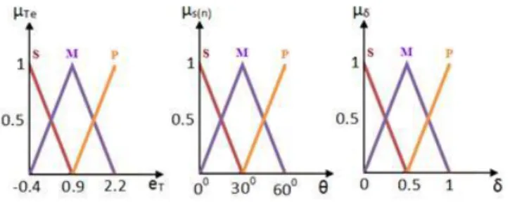
The inputs of fuzzy controllers Torque (eT), Sector angle(θ) and output duty cycle(δ) are represented by three linguistic variables: small(S), Medium(M) and Large(L) represented by triangular membership functions as shown in Figure 6. [31-32].
Table 2. Rule base for Fuzzy Controllers1 and 2 [31] Torque
error
Position of stator flux S(n)
S M L
Stator flux < Ref.Value
Fuzzy contoller1
S M S S
M M M M
L L L L
Stator flux < Ref.Value
Fuzzy Contoller2
S S S M
M M M L
L L L L
5. DUTY RATIO CONTROLLER USING NEURAL NETWORKS
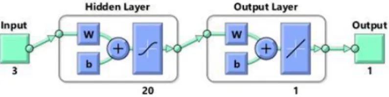
The duty ratio controller is implemented using Artificial Neural Networks. Feed forward neural network with one hidden layer is trained for evaluation of optimal duty ratio fed to FDTC of Induction motor. The neural network is developed using neural network toolbox in Matlab. The NNDRC has three inputs Torque error, Reference flux, stator flux angle and one output duty ratio. The 80000 samples of inputs, output are collected to develop the neural net. On typing “nftool” in command window we can open neural network fitting tool, the inputs and targets are imported from file stored in. Mat file. The neural net training is begun by setting validation and testing as 15% neural network architecture is chosen.
The feed forward, back propagation neural net with one hidden layer is selected. The hidden layer of 20 neurons with “Tansig” (sigmoid transfer function) is selected and output layer of one neuron with “Purelin” (linear transfer function) as shown in Figure 7. The neural networks are trained using Levenburg-Marquardt algorithm. ANN learns by adaptation of weights in order to conform to the target with Mean square error set to zero. The best validation at 1000 epoch is shown in Figure 8. Once the training is finished the neural network Simulink block is generated using “gensim”, as shown in Figure 9. Which is placed in the Simulink model to replace fuzzy logic based duty ratio controller. The trained neural network will select the optimal duty ratio based on the torque error, reference flux and stator flux angle. The selected optimal duty ratio (δ) is applied to switching vector of VSI.
Figure 7. Neural Networks based duty Ratio Controller Architecture
Figure 9. Simulink Model of Neural Network based DRC
6. RESULTS AND ANALYSIS
In order to test the effectiveness of Fuzzy logic switching controller with Fuzzy duty ratio controller and Neural Network based duty ratio controller in improvement of dynamic and steady state response of drive, respective Simulink models are simulated using Matlab software. The Induction motor initially subjected to a reference speed of 50 rad/sec and given a sudden change to 100 rad/sec at t=0.4 sec to measure transient and steady state behavior of drive. Initially the motor is started with no-load and subjected a sudden load of 4 N-m at t=0. 2 Sec in order to test the effectiveness of feedback loop. Induction motor is developed based on the parameters listed in Table 3. All simulations are carried over a sampling time of 1/10000 Sec which is equivalent to sampling frequency of 10 kHz.
Table 3. Induction motor Parameters
Symbol Parameters values
Pn Power 1.1 kW
V n Nominal Voltage 400/230 V
In Nominal current 2.6 /4.5 A
n Nominal Speed 1420 rpm
F Frequency 50 Hz
p Pair pole 2
Rs Stator resistance 7.6 Ω
Rr Rotor resistance 3.6 Ω
Ls Stator inductance 0.6015 H
Lr Rotor inductance 0.6015 H
Lm Mutual inductance 0.5796 H
J Moment of inertia 0.0049 Kg·m2
Figure 11. (a), (b) & (c) illustrates the speed response of CDTC, FDTC with fuzzy DRC and NN DRC. Figure 11 (a) clearly indicated peak overshoot when the motor is subjected to step change in reference speed. Figure 11 (b) & 11 (c) shows that the speed response is smooth without any overshoots, Proposed FDTC with the duty ratio controller are able to track smoothly the sudden variation in reference speed.
Figure 12. (a), (b) & (c) illustrates the Torque response of CDTC, FDTC with fuzzy DRC and NN DRC. Figure 12 (a) clearly indicates high torque ripple of around reference value (4±1.2 N-m) due to presence of hysteresis band and conventional switching table. Figure 12 (b) & (c) shows that torque ripples are reduced by 85 % (4±0.2 N-m) in case of FDTC with Fuzzy DRC. Figure7 (c) illustrates that torque response is smoother and less ripple in FDTC with NN DRC compared to CDTC and FDTC with Fuzzy DRC.
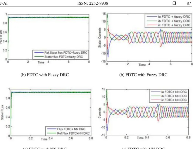
(b) FDTC with Fuzzy DRC (b) FDTC with Fuzzy DRC
(c) FDTC with NN DRC (c) FDTC with NN DRC
Figure 11. Speed response of induction motor Figure 12. Torque response of induction motor
Figure 13. (a), (b) & (c) illustrate the Flux response of CDTC, FDTC with fuzzy DRC and NN DRC. Figure 13(a) clearly indicates high flux ripples around reference value (0.924 ±0.08 N-m) using conventional switching table. Figure 13 (b) & (c) shows that Flux ripples are reduced by 75 % (0.924 ±0.02 N-m) in case of FDTC with Fuzzy DRC and FDTC with NN DRC compared to CDTC.
Figure 14. (a), (b) & (c) illustrate the 3 phase Stator currents drawn by induction motor using CDTC, FDTC with fuzzy DRC and NN DRC. Figure 14 (a) clearly indicates the current drawn using CDTC contains large amount of harmonics compared to currents drawn by using FDTC with Fuzzy DRC and FDTC with NN DRC as depicted in Figure14 (b) & 14 (c).
(b) FDTC with Fuzzy DRC (b) FDTC with Fuzzy DRC
(c) FDTC with NN DRC (c) FDTC with NN DRC
Figure 13. Stator Flux response of induction motor Figure 14. Stator currents of induction motor
(a) CDTC (b) FDTC with Fuzzy DRC (c) FDTC with NN DRC
Figure 15. Stator Flux Trajectory path of Induction motor
Figure 15. (a), (b) & (c) illustrate the flux trajectory path using CDTC, FDTC with fuzzy DRC and NN DRC. Figure 15 (b) clearly indicates that smooth flux trajectory during switch of states is observed in FDTC with Fuzzy DRC compared to other two schemes
7. CONCLUSION
This paper proposes the use of Fuzzy logic controller along with Fuzzy and Neural Network based duty ratio controller for improvements in Sensorless Conventional DTC of Induction motor. The Fuzzy Logic switching controller selects optimal switching state to meet the torque demand and reference speed of Induction motor. But the switching state selected will be applied for an entire switching period. Fuzzy Duty
ratio controllers and Neural Networks based Duty ratio controller generates optimal duty ratio (δ) which indicates the time for which active switching state is applied and zero switching state is applied remaining time. Simulation results validate that Using FDTC with Fuzzy DRC or NN DRC the torque and flus ripples are reduced, improved dynamic and steady state response of induction motor can be achieved. In Fuzzy DRC once the rule base is prepared it will be validated for all changes in reference speed or load Torque. In NN DRC we need to retrain the neural network for selection of optimal duty ratio. So DTC with Fuzzy switching controller and Fuzzy DRC we can achieve fast dynamic response and improved steady response of induction motor can be achieved.
REFERENCES
[1] I. Takahashi and T. Noguchi, "A New Quick-Response and High-Efficiency Control Strategy of an Induction Motor," in IEEE Transactions on Industry Applications, vol. IA-22, no. 5, pp. 820-827, Sept. 1986.doi: 10.1109/TIA.1986.4504799.
[2] I. Takahashi and Y. Ohmori, "High-performance direct torque control of an induction motor," in IEEE Transactions on Industry Applications, vol. 25, no. 2, pp. 257-264, Mar/Apr 1989.doi: 10.1109/28.25540P.
[3] Peter Vas, “sensorless Vector and Direct Torque Control”, Oxford University Press,1998.
[4] M. P. Kazmierkowski and A. B. Kasprowicz, "Improved direct torque and flux vector control of PWM inverter-fed induction motor drives," in IEEE Transactions on Industrial Electronics, vol. 42, no. 4, pp. 344-350, Aug 1995.doi: 10.1109/41.402472.
[5] Sudheer H, Sarvesh B and Kodad SF “Improved Fuzzy Logic based DTC of Induction machine for wide range of speed control using AI based controllers” Journal of Electrical Systems, 12-2(2016).301-314.
[6] Jun-Koo Kang and Seung-Ki Sul, "New direct torque control of induction motor for minimum torque ripple and constant switching frequency," in IEEE Transactions on Industry Applications, vol. 35, no. 5, pp. 1076-1082, Sep/Oct 1999.doi: 10.1109/28.793368.
[7] P. Z. Grabowski, M. P. Kazmierkowski, B. K. Bose and F. Blaabjerg, "A simple direct-torque neuro-fuzzy control of PWM-inverter-fed induction motor drive," in IEEE Transactions on Industrial Electronics, vol. 47, no. 4, pp. 863-870, Aug 2000.doi: 10.1109/41.857966.
[8] Fatiha Zidani, Rachid Nait, “Direct Torque Control of Induction Motor with Fuzzy Minimization Torque Ripple”, Journal of Electrical Engineering. 56(7-8): 183-18.
[9] Y. Zhang, J. Zhu, Z. Zhao, W. Xu and D. G. Dorrell, "An Improved Direct Torque Control for Three-Level Inverter-Fed Induction Motor Sensorless Drive," in IEEE Transactions on Power Electronics, vol. 27, no. 3, pp. 1502-1513, March 2012. doi: 10.1109/TPEL.2010.2043543.
[10] S. S. Sebtahmadi, H. Pirasteh, S. H. Aghay Kaboli, A. Radan and S. Mekhilef, "A 12-Sector Space Vector Switching Scheme for Performance Improvement of Matrix-Converter-Based DTC of IM Drive," in IEEE Transactions on Power Electronics, vol. 30, no. 7, pp. 3804-3817, July 2015. doi: 10.1109/TPEL.2014.2347457.
[11] S. Kouro, R. Bernal, H. Miranda, C. A. Silva and J. Rodriguez, "High-Performance Torque and Flux Control for Multilevel Inverter Fed Induction Motors," in IEEE Transactions on Power Electronics, vol. 22, no. 6, pp. 2116-2123, Nov. 2007.doi: 10.1109/TPEL.2007.909189.
[12] S. A. Mir, M. E. Elbuluk and D. S. Zinger, "Fuzzy implementation of direct self-control of induction machines," in IEEE Transactions on Industry Applications, vol. 30, no. 3, pp. 729-735, May-June 1994.doi: 10.1109/28.293723. [13] S. Gdaim, A. Mtibaa and M. F. Mimouni, "Design and Experimental Implementation of DTC of an Induction
Machine Based on Fuzzy Logic Control on FPGA," in IEEE Transactions on Fuzzy Systems, vol. 23, no. 3, pp. 644-655, June 2015. doi: 10.1109/TFUZZ.2014.2321612.
[14] P. Vas, A. F. Stronach, M. Rashed and M. Neuroth, "Implementation of ANN-based sensorless induction motor drives," Electrical Machines and Drives, 1999. Ninth International Conference on (Conf. Publ. No. 468), Canterbury, 1999, pp. 329-333. doi: 10.1049/cp:19991045.
[15] Sudheer H, Kodad SF and Sarvesh B, “Direct Torque and Flux control of Induction Machine using Fuzzy Logic controller” in journal of Atti dellA “FondAzione GiorGio ronchi” Italy Anno IXXI, 2016 - n. 3 pp: 243-253. [16] Fayez G. Areed, Amira Y. Haikal, Reham H. Mohammed, Adaptive neuro-fuzzy control of an induction motor, Ain
Shams Engineering Journal, Volume 1, Issue 1, September 2010, Pages 71-78, ISSN 2090-4479, http://dx.doi.org/10.1016/j.asej.2010.09.008.
[17] A.L. Orille, G.M.A. Sowilam, Proceedings of the 24th international conference on computers and industrial engineering Application of neural networks for direct torque control, Computers & Industrial Engineering, Volume 37, Issue 1, 1999, Pages 391-394. http://dx.doi.org/10.1016/S0360-8352(99)00101-1.
[18] Xuezhi Wu and Lipei Huang, "Direct torque control of three-level inverter using neural networks as switching vector selector," Industry Applications Conference, 2001. Thirty-Sixth IAS Annual Meeting. Conference Record of the 2001 IEEE, Chicago, IL, USA, 2001, pp. 939-944 vol.2. doi: 10.1109/IAS.2001.955565.
[19] S. Gdaim, A. Mtibaa and M. F. Mimouni, “Direct Torque Control of Induction Machine based on Intelligent Techniques," International Journal of Computer Applications (0975 – 8887) Volume 10– No.8, November 2010, pp.29-34.
[21] Pengcheng Zhu, Yong Kang and Jian Chen, "Improve direct torque control performance of induction motor with duty ratio modulation," Electric Machines and Drives Conference, 2003. IEMDC'03. IEEE International, 2003, pp. 994-998 vol.2.doi: 10.1109/IEMDC.2003.1210356.
[22] Y S Kishore Babu, G Tulasi Ram Das. Improvement in Direct Torque Control of Induction motor using Fuzzy Logic Duty Ratio controller. ARPN Journal of Engineering and Applied Sciences,2010; Vol.5(4) pp. 68-73. [23] Milan Zalman, Ivica Kuric. Direct Torque and flux control of Induction machine and fuzzy controller. Journal of
Electrical engineering, 2005; Vol. 56(9-10), pp.278–280.
[24] Sudheer H, Kodad SF, Sarvesh B, “Torque Ripple Reduction in Direct Torque Control of Induction Motor using Fuzzy Logic based Duty Ratio Controller”, International Journal of Electronic Engineering Research. 2011; Vol 3(1), pp.1-12.
[25] J. Vonkomer and M. Žalman, "On the stability of current based MRAS," Industrial Electronics Society, IECON 2013 - 39th Annual Conference of the IEEE, Vienna, 2013, pp. 3018-3023. doi: 10.1109/IECON.2013.6699611. [26] T. Orlowska-Kowalska and M. Dybkowski, "Stator-Current-Based MRAS Estimator for a Wide Range
Speed-Sensorless Induction-Motor Drive," in IEEE Transactions on Industrial Electronics, vol. 57, no. 4, pp. 1296-1308, April 2010. doi: 10.1109/TIE.2009.2031134.
[27] J. Vonkomer and M. Zalman, "Induction motor sensorless vector control for very wide speed range of operation," Carpathian Control Conference (ICCC), 2011 12th International, Velke Karlovice, 2011, pp. 437-442. doi: 10.1109/CarpathianCC.2011.5945896.
[28] Juraj Gacho, Milan Zalman, “IM based speed servo drive with Luenberger observer”, Journal of ELECTRICAL ENGINEERING, VOL. 61, NO. 3, 2010, pp.149–156.
[29] Abbou A, Mahmoudi H, “Performance of a sensorless speed control for induction motor using DTFC strategy and intelligent techniques”, Journal of Electrical Systems. Volume 5, Issue 3, September 2009.
[30] Riad Toufouti, Salima Meziane, Hocine Benalla , Direct Torque Control Strategy of Induction Motors , Acta Electrotechnica et Informatica, No. 1, Vol. 7, 2007 pp:1-7.
[31] Sudheer H, Kodad SF and Sarvesh B, "Optimal duty ratio controller for improved DTFC of induction motor using Fuzzy logic," 2016 IEEE Students' Conference on Electrical, Electronics and Computer Science (SCEECS), Bhopal, India, 2016, pp. 1-6.doi: 10.1109/SCEECS.2016.7509321.
[32] Sudheer H, Kodad SF, Sarvesh B, “Improved direct torque control of Induction motor suing Fuzzy Logic based Duty ratio controller”, International Journal of Advances in Engineering and Technology, Nov 2011, pp. 473-479. [33] Y. Zhang and H. Yang, "Model Predictive Torque Control of Induction Motor Drives With Optimal Duty Cycle
Control," in IEEE Transactions on Power Electronics, vol. 29, no. 12, pp. 6593-6603, Dec. 2014.doi: 10.1109/TPEL.2014.2302838.
[34] C. Xia, J. Zhao, Y. Yan and T. Shi, "A Novel Direct Torque Control of Matrix Converter-Fed PMSM Drives Using Duty Cycle Control for Torque Ripple Reduction," in IEEE Transactions on Industrial Electronics, vol. 61, no. 6, pp. 2700-2713, June 2014. doi: 10.1109/TIE.2013.2276039.
[35] Y. Ren, Z. Q. Zhu and J. Liu, "Direct Torque Control of Permanent-Magnet Synchronous Machine Drives With a Simple Duty Ratio Regulator," in IEEE Transactions on Industrial Electronics, vol. 61, no. 10, pp. 5249-5258, Oct. 2014.doi: 10.1109/TIE.2014.2300070.
BIOGRAPHIES OF AUTHORS
Sudheer Hanumanthakari received the B. Tech degree in EEE from JNTU, Hyderabad and M. Tech Degree in Power Electronics from JNTU, Hyderabad and currently pursuing PhD. in Electrical Engineering at JNTU, Anantapur. He has got a teaching experience of nearly 10 years He is currently working as Asst. Professor in FST-IFHE (ICFAI University), Hyderabad. His areas of interests are neural networks and fuzzy logic applications in power electronics drives.
Dr. S. F. Kodad received the B.E.degree in EEE from from Karnataka University and the M. Tech. Degree in Energy Systems from JNTU, Hyderabad, India in the year 1992. He received his Ph.D. degree in Electrical Engg. from JNTU, Hyderabad, India in the year 2004. He has got a teaching experience of nearly 20 years. He has published a number of papers in various national & international journals & conferences. He has also presented a number of guest lectures and various seminars and participated in a number of courses, seminars, workshops, symposiums in the various parts of the country in different institutions and also conducted a few courses. He is also guiding a number of Ph.D. students. His area of interests are neural networks, fuzzy logic, power electronics, power systems, artificial intelligence, Matlab, Renewable energy sources, etc.
Dr. Sarvesh Botlaguduru received the B. Tech degree in EEE from JNTU, Anantapur and M. Tech in Instrumentation and Control from SV University, Tirupathi. He received his Ph.D. degree in Electrical Engg. From IIT, Kharaghpur India in the year 1995. He has got a teaching experience of nearly 30 years. Currently, he is working as Professor and Head of EEE in JNTUA, Anantapur, and Andhra Pradesh, India. His areas of interests are Instrumentation and Control, Control Systems.
![Figure 1. Block Diagram of Conventional DTC [20]](https://thumb-us.123doks.com/thumbv2/123dok_us/8385016.2227838/2.892.176.741.799.1062/figure-block-diagram-conventional-dtc.webp)