Image Enhancement by Using
Directional Wavelet Transform
D. Heric, B. Potocnik
University of Maribor, Faculty of Electrical Engineering and Computer Science, Slovenia
The purpose of this paper is to introduce a novel im-age enhancement technique by using directional wavelet transform. Directional wavelet transform decomposes an image into four-dimensional space which augments the image by the scale and directional information. We show that the directional information significantly improves image enhancement in noisy images in comparison with the classical techniques. Image enhancement is based on the multiscale singularity detection with an adaptive threshold whose value is calculated via maximum en-tropy measure. The proposed technique was tested on synthetic images at different signal-to-noise ratios and clinical images.
Keywords: image enhancement, wavelet transform, di-rectional wavelet transform.
1. Introduction
Image enhancement is a technique which re-duces image noise, removes artefacts, and pre-serves details. Its purpose is to amplify certain image features for analysis, diagnosis and dis-play. The technique can be performed by either suppressing the noise or increasing the image contrast [1]. A comprehensive survey of en-hancement methods has been published in[2]. Elementary enhancement techniques are histo-gram-based. They are simple, fast, and with them acceptable results for some applications can be achieved. But their biggest disadvan-tages are limited ability to incorporate local context into the transformation. Afterward, an adaptive histogram equalization technique has been proposed [3], which brings a limited improvement, because fixed contextual regions cannot adapt to features of different size. In an attempt to overcome these limitations, another,
more advanced and most widespread enhance-ment algorithm has been proposed which has a common strategy-edge sharpening.
The technique of unsharp masking has become a popular enhancement to assist in diagnosis[3]. Unsharp masking sharpens the edges by sub-tracting a portion of a filtered component from an original image[4]. An extension of this tech-nique is the Laplacian filtering proposed in[5]. However, techniques of unsharp masking are less efficient for images containing a wide range of features because of their singlescale proper-ties. Refinements were introduced in [6, 7, 8] with novel local contrast measure and nonlinear transform function. Their major drawback is the absence of explicit noise suppression model that can cause aplification of the noise or arte-facts.
An advancement of wavelet theory has taken the interest of researchers in its application to image enhancement [9, 10, 11, 12]. In[11]the enhancement is done by noise removing and edge enhancement. The algorithm relies on a multiscale edge representation where the noise is connected to the singularities. In[12]the non-linear wavelet shrinkage algorithm is proposed which reduces wavelet coefficients toward zero, based on a level-dependent threshold. In this work, we give a detailed mathematical analy-sis of a directional wavelet transform and reveal its connection with the edge enhancement. In addition, we discuss a single level edge sharp-ening, followed by its refinement to a multiscale sharpening.
Sec-tion 3 introduces a single scale edge sharpening method. Section 4 deals with image enhance-ment. Section 5 presents some experimental results and compares with Laplacian sharpen-ing. Finally, Section 6 concludes this work and suggests possible future research directions.
2. Directional Wavelet Transform
Natural images are not simple stacks of 1-D piecewise smooth scan–lines; discontinuity points (i.e. edges) are typically located along smooth curves(i.e. contours)owing to smooth boundaries of physical objects. Thus, natural images contain intrinsic geometrical structures that are key features in visual information[13]. In order to identify such structures, their orien-tation bears a crucial piece of information.
The wavelet transform[14]has a long and suc-cessful history as an efficient image processing tool. However, as a result of a separable exten-sion from 1-D bases, wavelets in higher dimen-sions can only capture very limited directional information. Different directions are mixed in certain wavelet subbands. For instance, 2-D wavelets only provide three directional compo-nents, namely horizontal, vertical, and diagonal. Furthermore, the 45◦ and 135◦ directions are mixed in diagonal subbands. With the direc-tional extension for wavelets proposed in [15]
that mixing problem can be improved, but not totally resolved. However, the wavelet trans-form is still very attractive for image processing applications.
A number of approaches in providing finer di-rectional decomposition have been proposed. Some notable examples include 2-D Gabor wavelets, the steerable pyramid, the directional filter bank, 2-D directional wavelets, complex wavelets, curvelets[16], ridgelets[16], and con-tourlets [13]. Among all, we decided to use directional wavelet transform[17]because it re-tains all beneficial properties of wavelets and provides additional directional information at the same time.
The directional wavelet transform (DWT) of discrete image I(m,n)is defined by(1)
Ks(α,τ1,τ1δ) =
M−1
m=0
N−1
n=0
1
√
αI(m,n)Q(δ)·
·κα(τ1−m,τ2−n)
(1)
whereαis the scale parameter,κα(m,n)stands
for 2-D mother wavelet kernel, whileM andN
represent the kernel’s size. Expression Q(δ)
is the rotator which rotates kernel κα
counter-clockwise by an angleδ. Kernelκα is defined
by(2)
κα(m,n) =ψα(n), m∈[0,M−1]. (2)
In the sequel, we derive the algorithm for the directional wavelet transform. As a wavelet function we decided to use the 1-D Mexican Hat function defined by
ψ(t) = 2 π1/4√3σ
t2 σ2 −1
e
−t2
2σ2
. (3)
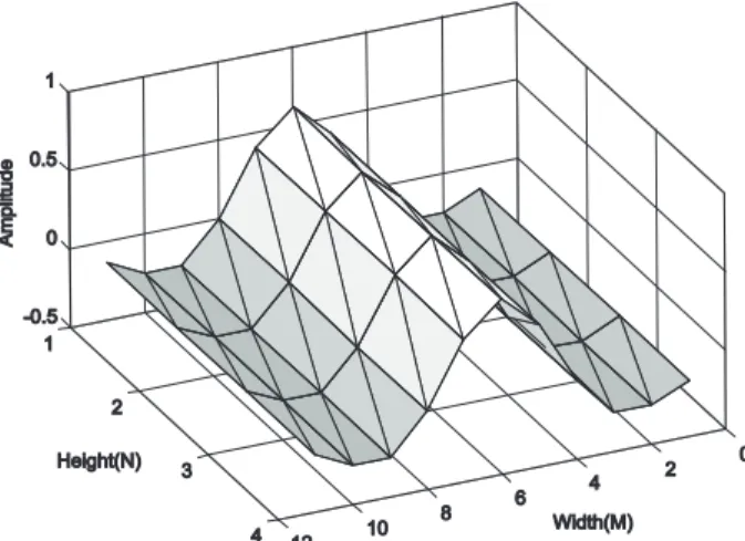
Mexican Hat is equal to the second derivative of a Gaussian and it was widely used in computer vision to detect multiscale edges[18, 19]. Thus, we use 2-D Mexican Hat kernel whose sample is depicted in Figure 1.
Fig. 1.Example of 2-D Mexican Hat kernel wavelet, where its width is 12 units, height 4 units and directional
angle is 0 degrees.
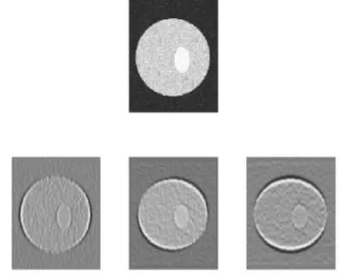
Fig. 2. A synthetic image(top)and DWT transformation results at directions 0,π/4 andπ/2(bottom).
Figure 3, however, exemplifies the DWT on a noisy synthetic image(Gaussian noise with zero mean and 0.01 variance). The second row in Figure 3 schematically depicts these results at directions 0,π/4, andπ/2.
Fig. 3.A noisy synthetic image(top)and DWT transformation results at directions
0,π/4 andπ/2(bottom).
From these examples it is clear that the kernels suppress all variations which are not parallel with their directions. Homogeneous regions re-sult in grey colour(Figure 2, bottom row). Also, the structures, e.g. isolated singularities along the line, create cones of large amplitude coeffi-cients between locations of these singularities. On the other hand, singularity neighbours with the same directions as kernels are emphasized as black and white pixels and significantly differ from the background. The singularity is visible as zero crossing. The more the singularity direc-tion corresponds with the operator orientadirec-tion, the more intensive is the obtained response. However, the main benefits of directional wavelet transform are: a) signal decomposition into four-dimensional space and b)capability of de-tecting the singularity lines.
3. Edge Sharpening
Edge sharpening is the reverse process of an edge blurring or image smoothing. To be effec-tive, it is essential that the magnitude of edge’s components is larger than that of existing noise. Simple edge sharpening scheme are done by selectively replacing a pixel point by its gradi-ent. The computation of gradient can be done by using a three-point or the four-point gradient expression. Well known linear gradient oper-ators are Laplacian operator, High-Pass Mask
[20], Compass gradient masks[20]and also non-linear operators, e.g. Sobel, Kirsch, and Wallis operator. In this work, we proposed the four-point gradient operator using least square plane interpolation.
Let I(x,y) be the image in the xy plane, and
z=ax+by+cbe a plane that fits the four neigh-bour points(i.e. approximation of four pixel val-ues by a plane). An error that results when the planezis taken as the image plane is defined by
Error2 =
[a(x) +b(y) +c−I(x,y)]2
+ [a(x+1) +b(y) +c−I(x+1,y)]2
+ [a(x) +b(y+1) +c−I(x,y+1)]2
+ [a(x+1) +b(y+1) +c−I(x+1,y+1)]2
(4) This quadratic error function is linear and can be analytically minimized by differentiating over unknown parameters a, b, and c. Setting this system of equations to 0, the result is repre-sented as follows
a= I(x+1,y) +I(x+1,y+1)
2
− I(x,y)−I2(x,y+1)
b= I(x,y+1) +I2(x+1,y+1) − I(x,y) +I2(x+1,y)
c= 14[3I(x,y) +I(x+1,y) +I(x,y+1) −I(x+1,y+1)−a−b]
One can see that parameter a gives the differ-ence of the average of pixels in two consecutive columns. Similarly, parameter b gives the dif-ference of the average of pixels in two consec-utive rows. System (5) defines the analytical model for searching local parameters of edge sharpening.
The gradient of the planezis defined by
G=
∂I ∂x
2 +
∂I
∂y
21/2
(6)
or
G= a2+b21/2 (7)
which can be approximated as
G=|a|+|b| or G=max(|a|,|b|). (8) This gradient is less sensitive to noise than Laplacian operator because the averaging is done prior to differencing. On the other hand, it is still sensitive to ripples in the imageI(x,y). Therefore, a lot of artefacts will be introduced when the least square plane operator is used alone. Due to this sensitivity, the additional noise reduction post-processing step is neces-sary. The variance is estimated and considered in order to distinct between edge point and noise point. Edge point has sufficiently higher vari-ance than a noise point. By using a window
(2M+1)x(2M+1), withMchosen between 2 and 4, the local variance can be estimated by
σ2(x,y) = 1 (2M+1)2· ·
x+M
k=x−M y+M
j=y−M
[I(k,j)−m(k,j)]2 (9)
where
m(x,y) = (2M1+1)2
x+M
k=x−M y+M
j=y−M
I(k,j).
(10)
Afterward, the distinction between “noisy vari-ance” and “edge varivari-ance” is evaluated. For threshold detection we decided to use Shannon entropy measure. It is a measure of information content where thresholdTis defined as the value which maximizesH =Hn+He. ParametersHn
andHeare defined by(11)
Hn(s(t)) = − T
i=1
pilog(pi)
He(s(t)) =− L i=T+1
pilog(pi)
(11)
where the signal magnitude of value i will oc-cur with probability pi in signal s(t). Signal
s(t)stands for the vector of gradient variances. The vector is quantized and rescaled to the in-terval[0,255]units. The thresholdTis a crucial parameter in the process of separation between edge and noisy pixels.
4. Image Enhancement
The image enhancement is defined as a process which reduces image noise, removes artefacts and preserves details. All these demands are partially achieved by edge sharpening and di-rectional wavelet transform. Using edge sharp-ening and the method for distinction between edge and noisy pixel, the basis for image en-hancement is set up. Additionally, with the directional wavelet transform the noise sensi-tivity of proposed technique is reduced because of multiscale and multidirectional approach. We decided to use the Mexican Hat wavelet or Marr wavelet which is a rotation-invariant with symmetric frequency response. Its main property is the ability to present magnitude variations between adjacent intervals in a sig-nal, which point out as the zero crossing from positive to negative or vice versa when pro-ceeding from scale to scale in the time-scale plane. The Mexican Hat kernel (Figure 1) also preserves this property in the image-scale-directional space.
The proposed image enhancement method con-sists of 7 major steps which are:
1. Directional wavelet transform is calculated with the Mexican Hat wavelet kernel at dyadic scales from 1 to log2(min(I,J)), whereI
2. A dimension reduction is implemented, so that only the maximum absolute value from the directional vector is kept for every trans-form space co-ordinate. It is clear that the Mexican Hat kernels which cross the sin-gularities perpendicularly aggregate higher maximum absolute values in the singularity neighbourhoods. This dimension reduction results in an image-scale space S(α,τ1,τ2). 3. Gradient calculation by plane approximation
(7)is done alongτ1 andτ2 directions in the image-scale space S(α, τ1, τ2). A plane, denoted as a gradient plane is obtained. 4. Noise reduction. Firstly, the detection of
noisy points is done by estimating the local variance(10), where the value M is set to 3 pixels. Points with local variance above the threshold valueT(11)are denoted as singu-larity (e.g. edge, feature) points. All other points belong to constant, textured or noisy area. A plane, denoted as a singularity plane is obtained.
5. Corresponding singularity points from sin-gularity planes (planes at different scales) are connected by using the same procedure as is used to connect the modulus maxima points introduced in [14]. Individual gularities are chained together to form sin-gularity lines that indicate the positions of singularity.
6. The singularity position is determined as the position of singularity at the lowest com-puted scale. The plane of singularities is obtained.
7. Finally, the image enhancement is done over the nearest samples of detected singular-ity points. Nearest samples are all points, which were used to calculate the directional wavelet transform value at the position of singularity point. Then the enhanced point value is calculated as the intensity of original image plus the value of image scale space at the scale at which the singularity point was detected. New image intensity values are calculated as
I(x,y) =I(x,y) +C·S(x,y) (12)
where parameter C controls the image con-trast. Function S represents the image-scale space. The result of our procedure is an image, where features, represented as the significant singularities, are enhanced.
5. Results
The proposed image enhancement algorithm was tested on a set of real images, as well as on synthetic images. Firstly, several tests and mea-surements were done over synthetic signals and images, which were corrupted by an additive zero-mean Gaussian noise. Besides the statis-tical evaluation, a visual assessment of clinical images was done.
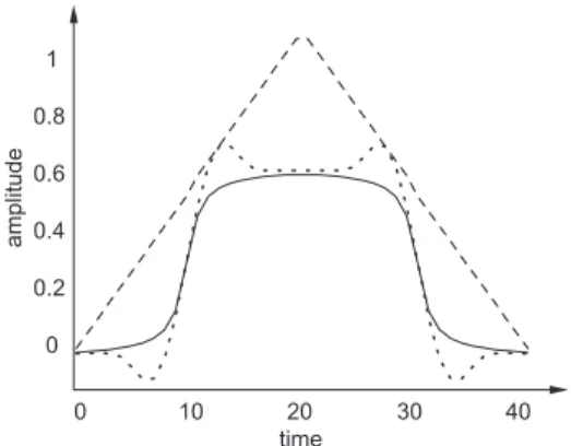
Fig. 4.1D contrast enhancement of a synthetic signal (solid line). Dashed and dotted lines belong to histogram equalization method and our proposed
method respectively(C=0.5).
Figure 4 depicts an 1D signal image enhance-ment example. Histogram equalization and our method are compared. Obviously, our method outperforms the classical histogram equaliza-tion method, because the edges are sharpened by our method, while by the histogram equal-ization they are more smoothed.
CII
\Images Original Histogramequalization Ourmethod
Noiseless 0.65 0.53 0.75
Noisy 0.46 0.51 0.71
Table 1.CII calculated on the original image, the histogram equalized image,
and the image equalized by our method.
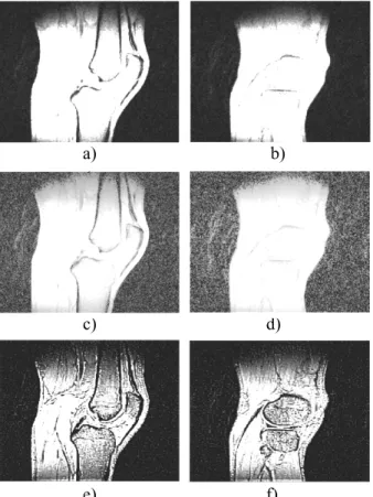
Fig. 5. Original images(1strow), histogram equalized
images(2ndrow), images enhanced by proposed method
with C=0.7(3rdrow).
After synthetic image validation we performed several tests on high-quality MR-images. Fig-ure 5 depicts results of the histogram equaliza-tion method and our method. One can see that after enhancement with both methods, signifi-cant structures like bones, ligaments, menisci, soft and hard tissues, are clearer and more vis-ible than before. But, we might say that our method better enhances the boundaries of small and thin structures, e.g. menisci, ligaments, and various tissues like patella.
6. Conclusion
A novel image enhancement procedure was pro-posed in this paper. This method combines directional wavelet transform and image gra-dient averaging by plane modelling. By us-ing directional wavelet transform the sus-ingular- singular-ity points pointed out as zero point crossing and having high local variance. Afterwards, the plane alignment among four-points in the image-scale plane is done. Its gradient indi-cates the singularity significance. At the end, the image is enhanced in the neighbourhood of most significant singularities. Testing with syn-thetic images has showed that proposed image enhancement technique is robust, accurate, and effective in noisy images too.
References
[1] I. PITAS, A. N. VENETSANOPOULOS, Nonlinear Dig-ital Filter: Principles and Applications, Kluwer Academic Publisher, Norwell, MA; 1990.
[2] D. C. WANG, A. H. VAGNUCCI, C. C. LI, Digital Image Enhancement, Computer Vision, Graphics, and Image Processing, 1983; Vol. 24; pp. 363–381. [3] A. LAINE, W. HUDA, Enhancement by Multiscale Nonlinear Operators,Handbook of Medical Imag-ing, Academic Press; 2000.
[4] A. ROSENFELD, A. KAK,Digital Picture Processing, 2nded. Academic Press, New York; 1982.
[5] F. NEYCENSSAC, Contrast enhancement using the
Laplacian-of-a-Gaussian filter, CVGIP:Graphical Models and Image Processing, 1985; Vol. 55: pp. 447–463.
[6] R. GORDON, R. M. RANGAYYAN, Feature
enhance-ment of film mammograms using fixed and adaptive neighbourhoods,Applied Optics1984; Vol. 23: pp. 560–564.
[7] A. BEGHDADI, A. L. NEGRATE, Contrast
enhance-ment technique based on local detection of edges, Comput. Vision Graphics Image Process1989; Vol. 46: pp. 162–174.
[8] W. QIAN, Medical Image Enhancement with Hybrid
Filters; 2000.
[9] A. F. LAINE, S. SONG, J. FAN, Adaptive Multiscale
Processing for Contrast Enhancement, in Proceed-ings of SPIE1993; Vol. 1905: pp. 521–532. [10] B. D. JAWERTH, M. L. HILTON, T. L. HUNTSBERGER,
[11] S. MALLAT, W. L. HWANG, Singularity detection
and processing with wavelets, IEEE Transactions on Information Theory1992; Vol. 38: pp. 617–643. [12] D. L. DONOHO, Nonlinear wavelet methods for
re-covery of signals, densities and spectra from indirect and noisy data,Proc. Symposia Applied Math.1993; Vol. 47: pp. 173–205.
[13] M. N. DO, Directional Multiresolution Image
Rep-resentationsPh.D. thesis, 2001.
[14] S. MALLAT,A Wavelet Tour of Signal Processing
2nd Ed.San Diego: Academic Press; 1999. [15] Y. LU, M. N. DO, A Directional Extension for
Mul-tidimensional Wavelet Transforms,IEEE Transac-tions on Image Processing, submitted; 2005. [16] E. CANDES` , Ridgelets: theory and applications,
Ph.D. thesis, Department of Statistics, Stanford University; 1998.
[17] D. HERIC, D. ZAZULA, Reconstruction of object
con-tours using directional wavelet transform, WSEAS Trans. Comput.2005; Vol. 4, pp. 1305–1312. [18] A. WITKIN, Scale space filtering.In Proceeding of
Int. Joint. Conf. Artificial Intell., Espoo, Finland 1983.
[19] C. W. TANG, H. M. HANG, A Feature-Based
Ro-bust Digital Image Watermarking Scheme, IEEE Transaction on signal processing2003, Vol. 51: pp. 950–959.
[20] S. BOW, Pattern Recognition and Image
Prepro-cessing, 2nd Ed. New York, Marcel Dekker, Inc.;
2002.
[21] W. M. MORROW, R. B. PARANJAPE, R. M. RAN
-GAYYAN, Region-based contrast enhancement of
mammograms, IEEE Transactions on Medical Imaging1992, Vol. 11: pp. 392–406.
Received:June, 2006 Accepted:September, 2006
Contact address: Dusan Heric Faculty of Electrical Engineering and Computer Scienc System Software Laboratory Smetanova 17, 2000 Maribor Slovenia e-mail:[email protected]
DUSANHERIC, born in 1978, received his BSc degree in 2002 from the University of Maribor. He currently holds a position of young researcher at the Faculty of Electrical Engineering and Computer Sci-ence, Maribor. His research field includes signal processing - wavelet transformation, image processing - segmentation, registration, cogni-tive vision and biomedicine. He is a member of IEEE Computer Society and of the Slovenian Pattern Recognition Society.
DR. BOZIDARPOTOCNIK, born in 1972, received his BSc degree in 2000