Intermediate Representations of Mobile Code
Wolfram Amme and Thomas S. Heinze Friedrich-Schiller-Universität Jena, Germany E-mail: {amme,theinze}@informatik.uni-jena.de
Jeffery von Ronne
The University of Texas at San Antonio, USA E-mail: [email protected]
Overview paper
Keywords:mobile code, intermediate representation
Received:April 3, 2007
Over the past decade, since Java was first introduced and integrated into the Netscape web browser, several intermediate representations have been developed that might be potentially used for mobile code applica-tions. This paper examines the requirements for a mobile code representation, presents several examples of stack-based, tree-oriented, and proof-annotating mobile code representations, and evaluates each of these representations according to the requirements.
Povzetek: ˇClanek podaja pregled mobilnih kod.
1 Introduction
In this era of the Internet, we increasingly come across mo-bile code applications (i.e., programs that can be sent in a single form to a heterogeneous collection of processors and will then be executed on each of them with the same semantics [1]). Such mobile code is usually intended to be loaded across a network and executed by an interpreter or after dynamic compilation on the target machine.
Unlike traditional monolithic, statically-compiled appli-cations, many modern applications are designed to be dy-namically composed from or extended with new compo-nents at runtime. An example of this is the Eclipse software development platform [17] that allows new plugins written in Java to be integrated into the environment. This dynamic extensibility is enhanced when the plugins can be described by executable code deployed in a mobile code representa-tion that has a greater compactness, portability, and safety than native binaries.
The Java Virtual Machine’s bytecode format (“Java Bytecode”) has become the de facto standard for trans-porting mobile code across the Internet. However, in the last decades several intermediate representations of mobile code have been developed, each of which could be used as an alternative to Java Bytecode. In the paper we give an overview of common intermediate representations, discuss the strengths and weaknesses of each, and finally compare its attributes with that of the other representations.
The intermediate representations designed for mobile code are complex and usually combine multiple features and mechanisms. Therefore, a clear classification of
mo-bile code representations is awkward. In contrast to other surveys, in which mobile code is examined from a pro-gramming language perspective [69] and for their verifica-tion time [45], respectively, our categorizaverifica-tion emphasizes the structure of the intermediate representation. In partic-ular the overview in [69] focuses on several programming languages (Java, Objective Caml, Telescript, etc.) and their suitability in mobile code environments. These languages are not classified by a taxonomy, but are introduced sequen-tially and evaluated according to some of the requirements imposed by the mobile code setting. In contrast, the ar-ticle [45] centers on compiling safe mobile code, stress-ing the importance of safety in the mobile code settstress-ing. It discusses the safety issues present in several intermedi-ate representations and compilation techniques, and classi-fies intermediate representations of mobile code according to their safety checking mechanisms, differentiating static, dynamic and hybrid mechanisms. The static mechanisms check critical safety properties at compile time (e.g., by static program analysis), while dynamic mechanisms rely on runtime safety checks (e.g., by inserting runtime checks into the code). Hybrid mechanisms apply a combination of static and runtime safety checks. In contrast, our classifi-cation does not focus on a single aspect (like safety) but highlights the general design of intermediate representa-tions used for mobile code and classifies them as stack-based, tree-oriented, or proof-annotated.
Sec-tion 3 presents our taxonomy and lists the primary repre-sentatives of each category. An evaluation and comparison of these intermediate representations is given in Section 4, and Section 5 concludes with a summary and a discussion about future directions in the area of mobile code represen-tations.
2 Mobile code and its requirements
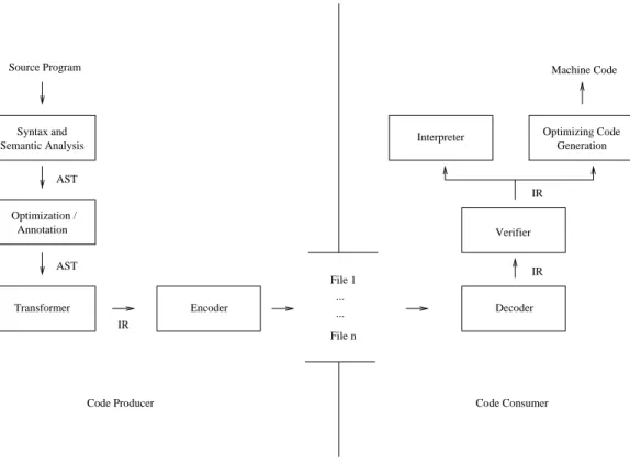
A system for transporting programs as mobile code can be partitioned into a producer side and a consumer side (see Figure 1). These two components communicate through files containing the mobile code in some intermediate rep-resentation (IR). The first step on the producer side is to analyze the input program syntactically and semantically and to transform it into an abstract syntax tree (AST). In the next stage, platform-independent optimizations can be performed, and annotations supporting consumer-side pro-gram analysis and optimization may be added to the ab-stract syntax tree in order to speed up dynamic code gener-ation. Finally, the program is transformed into the chosen intermediate representation, and after being encoded as a— possibly compressed—binary, they are stored into files.
These files containing mobile code are then transferred to the consumer side where they are decoded. Next, the transmitted program has to be examined to determine if it adheres to the security requirements of the mobile code for-mat. This verification process can use a variety of mech-anisms ranging from simple type checks to validation of digital signatures or even the verification of proofs about program properties. If no violations are found, the pro-gram is executed on the target machine. The execution environment can execute the program by interpreting it or using a just-in-time (JIT) compiler to generate native ma-chine code that runs directly on the target mama-chine. In or-der to improve performance, JIT compilers often perform machine-dependent optimizations on the program code; this consumer-side optimization is sometimes enhanced by producer-side program annotations. To fulfill the require-ments of a mobile code framework, special attention needs to be paid to the choice of intermediate representation. A candidate intermediate representation of mobile code can be evaluated on its ability to satisfy several desirable prop-erties [25]:
Portability: An important property of an intermedi-ate representation of mobile code is high portability. The mobile code needs to be able to execute on dif-ferent target platforms, so the intermediate represen-tation must be independent from any specific target machine’s architecture.
CompactnessAn intermediate representation should also be dense. Originally, this requirement was due to restricted memory on some of the target code con-sumers, but today it is more important for reducing
transmission times. This property is still critical, espe-cially with respect to dynamically loaded mobile pro-grams.
Flexibility: If an intermediate representation is not bounded to a specific input programming language, it can be used for a wide range of languages. This im-plies the advantage, as stated in [35], of implementing onlyncode-producers andmcode-consumers instead of implementingn*mcompilers. To attain high flex-ibility, the intermediate representation must support a versatile instruction set and an abstract type model.
Safety:In a mobile code system, the partitioning into code-producer and code-consumer leads to situations, in which the mobile code is not delivered directly by a trusted code-producer. Therefore, the question comes up as to how the code-consumer can ensure that the execution of the mobile code does not maliciously or accidentally affect the local machine in an unautho-rized manner. Hence, an appropriate intermediate rep-resentation must support verification techniques to as-certain safety properties as type and memory safety.
Efficiency:Finally, although efficiency ultimately de-pends on the quality of the mobile code system imple-mentation, the intermediate representation of a mobile code system should facilitate, or at least not hinder, the efficient execution of mobile code applications. This property is affected by the way the mobile code is executed: interpreted or compiled just in time. An interpreter-based implementation usually yields lower memory and other resource usage, and is often the most appropriate implementation for embedded sys-tems. An implementation based on just-in-time com-pilation, however, usually results in faster execution of frequently executed mobile code and also supports machine-dependent program optimizations. Features that make a program representation easier to inter-pret may make it more difficult to optimize during JIT compilation or vice versa.
An optimal intermediate representation for mobile code should satisfy all of these properties, however in practice, the representation’s designer may have to make design de-cisions that prioritize one over the other. As an example, increases in the safety guarantees often incur a loss of effi-ciency due to the increased costs of the verification process. Therefore, even though a representation cannot maximize all of these properties simultaneously, a mobile code rep-resentation can be evaluated on the basis of how well it satisfies these requirements.
3 Verifiable mobile code
representations
mo-Interpreter
... ...
Code Consumer Code Producer
File 1
File n
Machine Code
Encoder Decoder
Source Program
AST
AST Optimization /
IR Syntax and
Semantic Analysis
Annotation
Optimizing Code Generation
IR Verifier
IR
Transformer
Figure 1: A general system for program transport by means of mobile code.
bile code consuming host system’s security in the pres-ence of malicious code. There are three main strategies that have been used—sometimes in isolation, sometimes in combination—to address this risk: cryptographic authenti-cation, sand-boxing, and verification.
The first strategy is to use cryptographic signatures to authenticate the mobile code’s producer and to prevent the mobile code from being tampered with during transit from the code producer. The code consuming system can then make decisions about the execution of the mobile code based on the trustworthiness of the code producer. In the simplest form (e.g., Microsoft’s ActiveX Controls [53]), this may simply be used to run or not to run the mobile code. In more complex situations, this is used in combi-nation with a security policy and “sand-boxing” to prevent mobile code from performing unauthorized actions.
A second strategy is to create a “sandbox” around the ex-ecuting mobile code and mediate all access to parts of the code consuming system outside of the sandbox. This al-lows the sandbox to prohibit those interactions that violate the code consuming system’s security policies. This sand-boxing can be implemented using operating-system level (e.g., VMWare, Xen, User Mode Linux) or process-level isolation (e.g., BSD jail, SELinux), but these techniques are too heavy-weight and too loosely integrated for use in many mobile code applications (e.g., a Java applet running on a cell phone). These problems can be addressed by using light-weight, fine-grain isolation integrated into the execu-tion environment.
A third strategy, often used to implement fine-grain iso-lation, is to analyze the mobile code and reject code that violates certain safety properties. Most commonly, this “verification” checks that the code is syntactically correct, has legal control flow, and that it is correctly typed. If the mobile code representation itself is type safe, this will guarantee the possible behavior (especially, with respect to memory accesses) of the mobile code to be constrained by the underlying mobile code representation’s type system. This in turn will allow the execution environment (e.g., the Java Virtual Machine) to sandbox mobile code com-ponents without necessitating the runtime overhead of op-erating system or process level techniques.
Successful implementation of this third strategy requires that the program representation is designed with verifi-cation in mind. The verifiable mobile code representa-tions that have been used in mobile code frameworks can be classified as being stack-based, tree-oriented, or proof-annotated representations.
3.1 Stack-based types
Most mobile code systems are based upon virtual ma-chines. In such mobile code systems, programs are trans-lated not into machine code for a specific target machine but rather into a platform independent intermediate repre-sentation. This intermediate representation consists of in-structions for an idealized “virtual” machine.
JVM *.class
*.class .. (*.java)
Java Compiler Source Program
Compile−Time Run−Time
Interpreter JIT Compiler
Machine code and Verifier
Classloader
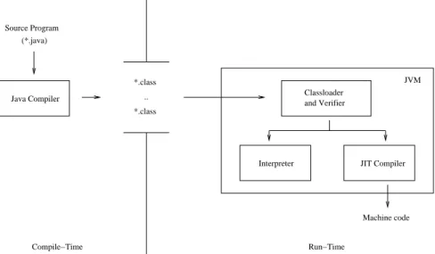
Figure 2: Java language infrastructure.
compiling it into equivalent machine code. Most often the virtual machine utilizes a stack-based architecture. In these virtual machines, most instructions implicitly take most of their operands from a stack and store most of their results back onto the same stack. One advantage of this archi-tecture is the compact encoding of instructions; since most operands are implicit, many instructions can be represented by a single opcode without any operands. These represen-tations are often designed so that each instruction can be encoded using a single byte, and for this reason the instruc-tion sets of stack-based virtual machines are often called bytecode.
Virtual machines have long been used in compiler con-struction. Starting in the 1970’s, compilers have used this concept to organize dependent and machine-independent phases into front end and back end of a com-piler. A representative example is P-Code [60], a stack-based intermediate representation used in some Pascal compilers. In the 1990’s,Sun MicroSystemsrevived inter-est in stack-based virtual machines with the Java program-ming language and its portable intermediate representation, Java Bytecode [34, 33]. Microsoft’s .NET Framework [63] also uses a stack-based intermediate representation called the Common Intermediate Language.
3.1.1 Java bytecode
Java Bytecode is a stack-based intermediate representation that was developed as type-safe program representation for Java programs. The instruction set and data types of Java’s Virtual Machine (JVM)1 are designed specifically for the Java programming language. In principle, Java Bytecode can also be used for other programming languages, but field reports show that a use of Java Bytecode for languages other than Java often can cause problems [23].
1A detailed description of JVM is given in [49].
The architecture for the typical deployment of Java as a mobile code system is given in Figure 2. On the producer-side of this system, a compiler translates a source program into portable Java Bytecode representing each Java method; all the methods in each class (with associated symbolic in-formation) are stored together in a Java “class file.” Af-ter successful transmission, the consumer-side JVM veri-fies the code to determine if it is safe to execute the mobile program. If the verification succeeds, the Java Bytecode is interpreted or executed directly after JIT compilation into machine code from the Java Bytecode.
The JVM’s most important components are a runtime stack, a program counter, and heap storage, which store objects, code segments, and symbolic information. If a method is invoked, a new method frame is created and placed by the JVM onto the top of the runtime stack. This method frame contains the values of parameters and local variables as well as information about the caller. In ad-dition, each frame contains an operand stack which is ac-cessed as Java Bytecode instructions need input operands and produce output results. Each slot of the operand stack can hold a 32-bit word, and two slots are needed for long or double values.
Figure 3(b) depicts the Java Bytecode program generated for a simple source code. In the program, the contents of local variablesaandbare added and its result afterwards is stored in local variable c. JVM assigns indices2 to all parameters and local variables within a method. These in-dices are used instead of their symbolic names to reference local variables and parameters. The density of Java Byte-code is increased by the inclusion of instructions which im-plicitly encode the indices of the first variables defined in a method.
In the sample program, the instructions iload_1 and
( a ) i n t a , b , c ;
c = a + b ;
( b )
i l o a d _ 1 ; push l o c a l v a r i a b l e a o n t o s t a c k i l o a d _ 2 ; push l o c a l v a r i a b l e b o n t o s t a c k i a d d ; add t o p m o s t s t a c k e l e m e n t s
i s t o r e _ 3 ; s t o r e t o p m o s t s t a c k e l e m e n t i n t o l o c a l v a r i a b l e c
( c )
l d l o c . 1 ; push l o c a l v a r i a b l e a o n t o s t a c k l d l o c . 2 ; push l o c a l v a r i a b l e b o n t o s t a c k add ; add t o p m o s t s t a c k e l e m e n t s
s t l o c . 3 ; s t o r e t o p m o s t s t a c k e l e m e n t i n t o l o c a l v a r i a b l e c
Figure 3: Java Bytecode (b) and CIL Bytecode (c) for a simple program (a).
iload_2 are used to push the values of a andb onto the operand stack. In contrast, the instruction istore_3 takes the topmost element from the operand stack and stores its value in variablec. Most of the bytecode instructions are typed (i.e., only accept operands of a specific type). The operations that start withigenerally indicate that they only accept values of typeintas operands. Thus, in the example program, instructioniaddtakes the two top-most int values from the operand stack, adds them, and stores the result back on the top of the operand stack.
The primary design consideration during the develop-ment of the JVM was its usefulness as a runtime environ-ment for Java. Therefore, the JVM’s instruction set is spe-cialized for the representation of Java programs. Java Byte-code supports four different method invocation instruc-tions implementing the virtual, super, static, and interface method calls of the Java programming language. For each method call, parameters are passed by value only, reference parameters are not supported directly. The JVM’s flex-ibility with respect to running programs written in other languages is also limited by the JVM’s provision of only single-inheritance for classes and multiple-inheritance for interfaces, respectively. Another disadvantage is the ab-sence of arithmetic exceptions beside the division-by-zero exception for integers.
Java Bytecode’s verification process includes static and dynamic checks and basically operates in four separate passes:
– Examination of general class file format
– Examination of additional structural properties of the class file
– Verification of the bytecode for each method
– Verification of inter-class dependencies during the ex-ecution of particular bytecode instructions
The examination of the transmitted Java Bytecode method (3rd pass) is performed by a data flow analysis,
which verifies that certain behaviors, which might violate the virtual machine’s type discipline (e.g., operand stack over- and underflows, unequal sizes of the operand stack on different control paths, usage of uninitialized local vari-ables, operands of incorrect types for the operation) cannot occur. Overall, the data flow analysis is quite complex and requires, in the worst case, quadratic time in the number of verified instructions[66].
In contrast to the first three passes (which are performed during loading and linking process), the last verification pass, which checks properties about external classes re-ferred to by bytecode instructions, occurs at runtime. In principle, all of the properties that are checked during this pass (e.g., that the classes referred to by an instruction exists) could be performed also during pass 3. But the JVM specification allows these checks to be deferred un-til run time, so that the loading of additional classes can be deferred until the instructions that refer to these addi-tional classes need to be executed. If one of these dynamic check fails, the execution of the instruction being checked is aborted and an exception is thrown.
3.1.2 Common intermediate language
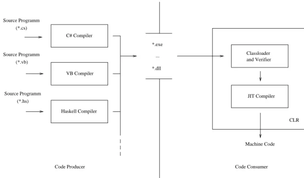
Microsoft Corporation’s Common Language Infrastructure Platform (CLI) is a runtime environment that has been de-veloped for running applications written in several differ-ent programming languages, including C#. CLI includes a stack-based virtual machine, called the Common Language Runtime (CLR), which can be used for execution of byte-code programs written in Common Intermediate Language (CIL). In contrast to JVM, the CLR standard does not an-ticipate execution with interpreter, but rather assumes all applications will be executed using JIT or ahead-of-time compilation.3
The .NET-Framework is Microsoft’s proprietary imple-mentation and extension of the CLI. In its current version,
C# Compiler
*.dll ... (*.cs)
(*.vb)
(*.hs) Source Programm
Source Programm
Source Programm
Haskell Compiler VB Compiler
*.exe
JIT Compiler
CLR
Machine Code Classloader and Verifier
Code Producer Code Consumer
Figure 4: .NET framework.
.NET uses two JIT compilers: A standard JIT compiler and Econo. .NET’s standard JIT compiler is an optimiz-ing compiler that supports several optimizations (e.g., con-stant propagation, method-inlining, common subexpres-sion elimination). In contrast, Econo is a non-optimizing JIT compiler that requires few system resources and, there-fore, is especially suited for deployment on mobile plat-forms with limited resources. In addition, in the .NET-Framework, programs (or parts of programs) may be com-piled in advance by the Pre-JIT compiler. Programs, that have been compiled with this compiler, are stored on the file system permanently, so that they can be executed di-rectly when needed in the future without needing to be re-compiled at runtime by the JIT compilation.
For each method invocation the CLR creates a new acti-vation record. An actiacti-vation record consists of fields con-taining method information, an instruction pointer, arrays for local variable and parameter definitions, and an eval-uation stack. The stack-architecture of the Common Lan-guage Runtime is realized by the evaluation stack, which is used like the operand stack of the JVM to store the operands and the results of CIL instructions. In contrast to the JVM operand stack, the CLR evaluation stack is ca-pable of storing elements of variable size.
Figure 3 (c) shows the CIL bytecode generated for the sample program from (a). Similar to local variable access in Java Bytecode, local variable and parameter accesses in CIL occur through indices assigned to variables and param-eters in the order of their declaration. In the example pro-gram, instructionldlocis used to push the value of a vari-able onto the evaluation stack. In contrast, instructionstloc takes the topmost element of the evaluation stack and stores
it in a variable. For each variable, there is a correspond-ing load instruction and a correspondcorrespond-ing store instruction to access that variable. These instructions are named by adding the variable number as a suffix (e.g. .1, .2, and .3,) to the operation name. In the example program, instruc-tion stloc.2 stores the topmost stack element in the local variableb(i.e., the local variable with associated index 2.) Unlike Java Bytecode, CIL offers the developer typed and untyped instructions. In the example program, the generic add-operationis used. Uses of this generic add-instruction require the CLR to infer the type of add-instructions during JIT compilation from its actual operand types.
In contrast to JVM, the CLI was developed with the in-tent of supporting many different programming languages. Therefore, the instruction set of CLR is designed around a general type system that is called Common Type System (CTS). Beside the standard primitive and reference types found in Java, the CTS also includes value types. A value type is essentially a restricted class, that is similar to a structure or enumeration type. Like the Java Virtual Ma-chine, the CTS offers only single-inheritance of classes but multiple-inheritance of interfaces. The flexibility of this type model is further enhanced by the instruction set of the CLR, which includes several instructions to make the execution of programming languages other than C# more efficient. For example, a .tail suffix can be appended to a method call instruction, causing it to discard the stack frame of the calling method; this is particularly important for the efficient implementation of functional languages, which make heavy use of recursive calls that would oth-erwise overflow the runtime stack.
(callvirtandcall) that can be used for virtual, non-virtual and static method calls. For parameter passing CLI of-fers call-by-reference and call-by-value mechanisms. In addition, parameters can be characterized as result parame-ters. Standard exception handling for operations on primi-tive data types are supported only for integer null-division. However, in contrast to JVM, in CLI add-, sub- and mult-instructions can be extended with special postfix operands to handle overflow exceptions.
When the producer side of the mobile code system trans-lates source programs into CIL, it packages them into “as-semblies.” An assembly contains a set of modules bundled together along with meta-data describing the classes and types defined in and used by those modules [50]. In con-trast to Java Bytecode’s class files, which contain only a single Java class, a CIL assembly is able to contain sev-eral classes. This facilitates the composition of applica-tion programs out of multi-module components and al-lows the producer-side compiler greater scope for inter-class and inter-procedural optimizations. The code within the modules provides sequences of Common Intermediate Language instructions defining the behavior of the methods declared in the assembly.
The CLR uses a verification process, similar to that of the JVM, to determine if it is safe to execute CIL programs. Unlike the JVM, the CLR can be configured to allow cer-tain programs to use “unmanaged” instructions, which can break the type safety of the runtime environment. These are provided in order to support a wide range of program-ming languages, including languages with unsafe features like pointer arithmetic. Normally, these unsafe instructions would be disabled when running mobile code.
The verification process is performed in two passes: val-idation and verification. In the valval-idation pass, the general assembly format and the proper use of the meta-data for-mat is ensured. Therefore, the validation pass corresponds to the first two passes of the Java Bytecode verification. In addition, a successful validation is a prerequisite for the verification pass, which is used to verify the control flow and then type-check the CIL module. This verification pass mirrors the last two passes of the Java Bytecode Verifica-tion and uses similar mechanisms.
3.2 Tree-oriented representations
Many compilers translate source programs into intermedi-ate representations based on abstract syntax trees. Tree-oriented mobile code representations are derived from these internal data structures, linearized into a stream of binary data so that they can be transmitted in files or across the network. Due to their close relationship to internal compiler structures, tree-oriented intermediate representa-tions are especially well-adapted to execution through JIT compilation, but they can also be interpreted.
A typical tree-oriented mobile code representations com-pilation unit consists of a source module’s abstract syn-tax tree and symbol table of a program (which would
typ-ically be generated during the compilation of the source program even if native machine code were to be targeted) [12, 29, 39, 28]. Since abstract syntax trees are typically machine-independent, tree-oriented intermediate represen-tations are often very portable. In addition, the semantic gap between source language and mobile code represen-tation is minimized compared to a translation into stack-oriented bytecode [66]. The advantages of this approach in-clude the retention of high-level program information (e.g., types and control structures), that can be useful for program optimizations, and a verification process that more closely resembles the type-checking of the source language. The primary disadvantage of this approach is that because it is closely tied to a single source language, it tends not to be very flexible with respect to supporting other source lan-guages.
Though not a true mobile code representation (since it does not address network transportation or ver-ifiability), the Architecture Neutral Distribution For-mat (ANDF) demonstrates the portability benefits of platform-independent tree-oriented program representa-tions. The compact tree-oriented representation, Slim Bi-naries, demonstrated the viability of transporting mobile code applets over networks using a tree oriented rather than a stack-oriented representation (like Java Bytecode). The SafeTSA representation is a hybrid representation that combines tree-oriented control structures with blocks of in-structions in static single assignment form, which is com-monly used as an intermediate representation of the back end of optimizing compilers.
3.2.1 ANDF
The Open Software Foundation’s Architecture Neutral Dis-tribution Format (ANDF) [61] was a subset of the Ten15 Distribution Format (TDF)4developed by the Defense Re-search Agency in the UK (DRA). TDF [13] is a tree struc-tured language, that is defined as a multi-sorted abstract algebra. It was originally designed for the compilation of sequential languages such as C and Lisp.
The intended usage was that programs would be dis-tributed in the ANDF, and then compiled into native code at installation time. As such, ANDF was designed solely as a distribution format with a tree-oriented program represen-tation that supports several source programming languages. Inside of the ANDF infrastructure (see Figure 5), the producer-side translates a program to distribute into ANDF, expressing platform specific information by standard appli-cation programming interfaces (API’s) [8]. Thereafter, the generated ANDF program is encoded into files and trans-mitted to the consumer-side, called installer. To install the transferred program, the ANDF files are compiled into tar-get platform’s machine code, and the installer replaces calls to an API with implementations provided by the target plat-form. Although originally developed for the C language,
(*.ada)
.. *.j
*.j
(*.c)
API− C Compiler
Source Program Source Program
Machine Code
Installer
ANDF Installer ANDF Producer
Ada95 Compiler
API Abstraction
Implementation
Figure 5: ANDF Scenario.
( a ) i n t i , j ;
i = i + 1 ; j = j + 1 ; i f ( i <= j )
i = i + 1 ; e l s e
i = i − 1 ; j = j + 1 ;
( b ) s e q u e n c e ( a s s i g n (
o b t a i n _ t a g ( ~ t a g _ 1 ) ,
p l u s ( c o n t e n t s ( i n t e g e r ( ~ s i g n e d _ i n t∗) , o b t a i n _ t a g ( ~ t a g _ 1 ) ) , m a k e _ i n t ( ~ s i g n e d _ i n t∗, 1 ) ) ) ,
a s s i g n (
o b t a i n _ t a g ( ~ t a g _ 2 ) ,
p l u s ( c o n t e n t s ( i n t e g e r ( ~ s i g n e d _ i n t∗) , o b t a i n _ t a g ( ~ t a g _ 2 ) ) , m a k e _ i n t ( ~ s i g n e d _ i n t∗, 1 ) ) ) ,
c o n d i t i o n a l ( ~ l a b e l _ 0 , s e q u e n c e (
i n t e g e r _ t e s t (
l e s s _ t h a n _ o r _ e q u a l , ~ l a b e l _ 0 ,
c o n t e n t s ( i n t e g e r ( ~ s i g n e d _ i n t∗) , o b t a i n _ t a g ( ~ t a g _ 1 ) ) , c o n t e n t s ( i n t e g e r ( ~ s i g n e d _ i n t∗) , o b t a i n _ t a g ( ~ t a g _ 2 ) ) ) , a s s i g n (
o b t a i n _ t a g ( ~ t a g _ 1 ) ,
p l u s ( c o n t e n t s ( i n t e g e r ( ~ s i g n e d _ i n t∗) , o b t a i n _ t a g ( ~ t a g _ 1 ) ) , m a k e _ i n t ( ~ s i g n e d _ i n t∗, 1 ) ) ) ,
a s s i g n (
o b t a i n _ t a g ( ~ t a g _ 1 ) ,
minus ( c o n t e n t s ( i n t e g e r ( ~ s i g n e d _ i n t∗) , o b t a i n _ t a g ( ~ t a g _ 1 ) ) , m a k e _ i n t ( ~ s i g n e d _ i n t∗, 1 ) ) ) ) ) ,
a s s i g n (
o b t a i n _ t a g ( ~ t a g _ 2 ) ,
p l u s ( c o n t e n t s ( i n t e g e r ( ~ s i g n e d _ i n t∗) , o b t a i n _ t a g ( ~ t a g _ 2 ) ) , m a k e _ i n t ( ~ s i g n e d _ i n t∗, 1 ) ) ) )
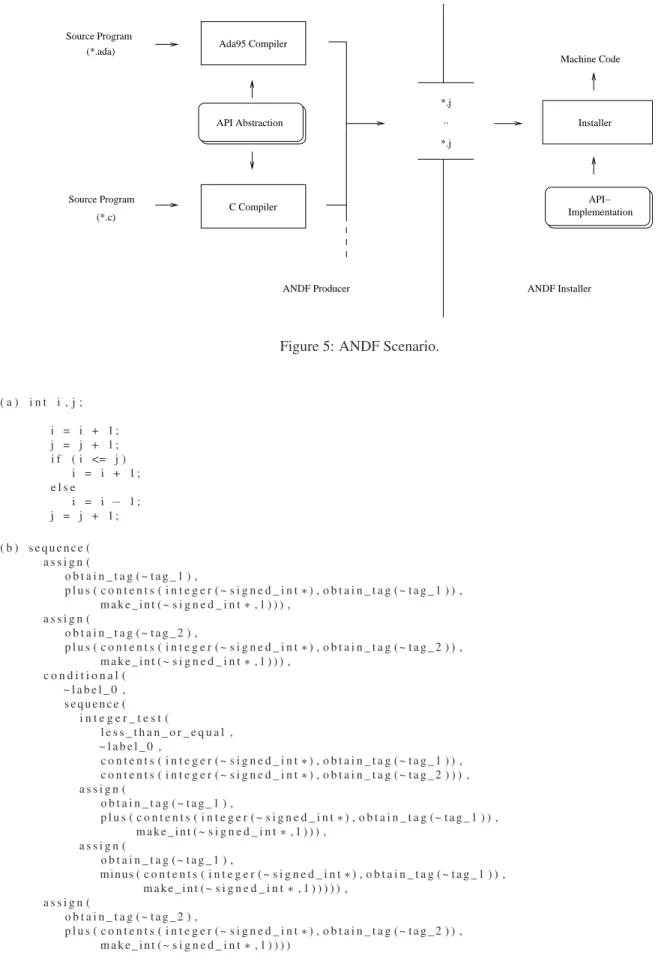
ANDF producers and installers are available for other pro-gramming languages and several machine architectures [9]. In TDF, the original program structure is maintained within the intermediate representation. The base element of the TDF is the sort constructor. Instances of this con-structor represent abstractions of expressions, descriptors, and data types. The shape constructor is used to describe data types within the TDF, including procedures, pointers, and recursive data types beside the primitive data types. Generic types can be defined in order to support platform specific data types, like the native integer type. Other sort constructors can be used to define specific memory layouts for data structures, exception handlers, and runtime stacks. TDF includes various operations, which can be separated into arithmetic, memory, pointer, and control flow oper-ations. Each operation is described using the expression constructor. Figure 6 (b) shows some simplified ANDF output for the example program given in (a). Descriptors (e.g., variables) in TDF are defined by the tag construc-tor. In this ANDF sequence, a unique integer is assigned to each tag constructor, in whichtag_1stands for variable iandtag_2describes variablej.
Platform independence is achieved in TDF through the provision of two constructs: the token constructor and the conditional constructor. The token constructor is essen-tially a parameterized placeholder, which can be replaced with an arbitrary sort constructor. Therefore, the token con-structor is used within TDF to hide platform specific pro-gram information by substituting calls to an API. In addi-tion, the conditional variant of several constructors allows one to specify platform specific installation tasks. A con-ditional constructor includes two constructors and a condi-tion: the installer evaluates the condition and maintains one of the constructors, corresponding to the result.
In general, the installation process of ANDF programs is separated into two steps. In the first step, calls to API’s, denoted by token constructors, are replaced with its corre-sponding implementation. In the second step, conditional constructors of the program are evaluated. As a result, the platform independent ANDF program is transformed on the consumer-side into a platform dependent ANDF pro-gram, which then is compiled into the machine code of the target platform and installed.
For the transport of ANDF programs, the algebraic TDF is linearized and stored in a capsule file. A capsule file consists of a byte array structured into sections. The first section includes the definitions of visibility rules for the en-coded ANDF program and acts as an interface. All of the token constructors used in the capsule are specified in the next section with the definitions of token constructors fol-lowing their declarations in order to simplify the encoding and decoding process. After all the token constructors have been specified, the program is stored in the following sec-tions using a linearized version of its TDF representation. A capsule file normally contains a single program, but it is possible to merge several capsule files into a single capsule library.
Verification of capsule files by the installer on the consumer-side is not integrated into the ANDF scenario, due to its development as a program distribution format. Instead, ANDF producers and installers are validated with respect to their conformity to the ANDF specification dur-ing a certification process [8]. For certification, ANDF producers and installers are validated separately. Valida-tion of an installer is based on a number of hand-written programs (i.e., the ANDF Validation Suite [40]), which must be executed accurately by an ANDF installer. Valida-tion of a producer is more difficult, because the produced ANDF code must execute correctly in any runtime envi-ronment for which there is an ANDF installer. Therefore, an architecture-independent high-level interpreter is used to evaluate the correctness of ANDF code generated by an ANDF producer for the ANDF Validation Suite.
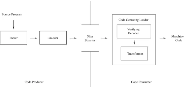
3.2.2 Slim binaries
The Slim Binary format [30, 21, 22] was originally de-veloped as an extension of the modular Oberon system, in which this format was used to provide architecture-independent distribution of Oberon modules. The name Slim Binaries was chosen to contrast with that of Fat Bina-ries [46], a name used for commercial distribution formats from Apple and Next, which stored binaries for multiple program architectures in a single file. Since Fat Binaries store one version of the entire program executable for each machine architecture, Fat Binaries tend to be large and re-quire a complex build process [28].
Slim Binaries avoid these disadvantages by using a portable and high-level intermediate representation, that is based on the encoded abstract syntax tree and symbol table of a program. In the extended Oberon system (see Figure 7), the producer-side translates Oberon modules into Slim Binary files and distributes them to several consumers. Af-ter successful transmission, a code-consumer can restore the syntax tree and symbol table from the r Slim Binaries and then verify its correctness. If this verification succeeds the syntax tree and symbol table are then used to generate the machine code of the target platform. In the actual im-plementation, a single code generating loader decodes Slim Binary files and generates code in an unified process.
The program representation contained in Slim Binary files consists of a compact description of the symbol table and a syntax-oriented encoding of the abstract syntax tree that is based on a technique called Semantic Dictionary En-coding (SDE).5In SDE the encoding is performed using a dynamically generated semantic dictionary table, in which each entry stands for a special type of node used in the ab-stract syntax tree. As a consequence, the abab-stract syntax tree of a program in Slim Binary format is not described through nodes directly, but through a sequence of indices, where each index stands for an entry in the dictionary table. The resulting sequence of indices is stored, conjoined with
Parser
Transformer Slim
Binaries Source Program
Encoder
Code Producer
Decoder Verifying
Code Consumer
Maschine Code Genrating Loader
Code
Figure 7: A Slim Binary Scenario.
the symbol table, in a file, which then can be transmitted to the code-consumer.
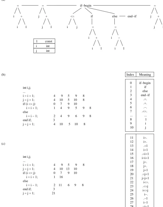
In SDE the dictionary table is generated in the exact same manner during encoding and decoding processes, therefore it is not necessary to store the dictionary table it-self into a Slim Binary file. Instead, the dictionary table of a program is rebuild automatically during decoding of the ab-stract syntax tree on the consumer-side. Construction of the dictionary table is always performed in three steps. First, the dictionary table is filled up with entries that describe the control structures and operators (e.g.,if,while,for, +, –, *, and /) of the used programming language. Second, the dictionary is augmented with entries from the symbol table for the variables and constants defined in the program. Fi-nally, the dictionary can be enhanced with special entries, which we will describe in detail later.
Figure 8 (a) contains the abstract syntax tree and the cor-responding symbol table for the same sample source pro-gram that was shown in Figure 6 (a), and Figure 8 (b) shows the sequence of indices resulting from applying the SDE. To simplify matters, the dictionary table shows only those entries which appear in the abstract syntax tree. In actual-ity, in order to describe all control structures and operators significantly more entries must be placed into the table. In SDE, a ‘.’ stands for operands that have not yet been pro-cessed, e.g. if the entry ‘.=.’ is selected, the left and right operands will need to be read. There are also dictionary entries (8 to 10 in our example) for each of the entries in the symbol table.
The dictionary table generated for our sample program can then be used for encoding the abstract syntax tree. For that purpose, the nodes of the abstract syntax tree are tra-versed in pre-order, and as each node is processed, the in-dex of its corresponding node class is written out. For example, the expressioni=i+1can be encoded as the se-quence of indices,4-9-5-9-8, corresponding to this expres-sion in prefix notation:=i+i1. Encoding of expressions in
prefix notation allows the abstract syntax tree of a program to be rebuilt directly as the Slim Binary file is processed.
Application of this simple SDE encodes each assignment of the sample program using at most 6 indices. On closer inspection, it is apparent that certain sequences reappear multiple times within the Slim Binary file (e.g., the encod-ing of the first and third assignment are identical). The Slim Binary format allows for the compression of recur-rences of similar patterns, by adding additional entries to the SDE during the encoding process that express patterns of nodes that have already been seen. As an example, after processing the assignmenti=i+1, entries for the subexpres-sionsi=.,i+.,.+1,i+1,.=i+1andi=i+1are inserted into the dictionary table. Figure 8 (c) shows excerpts of the dic-tionary table extension that would be adaptively built up during the encoding of our sample program. As can be seen, this SDE dynamic extension mechanism reduces the number of indices required for the sample program from 32 to 24 indices.
The insertion of additional entries for the description of these subexpressions increases the size of the dictionary ble and with it the number of bits that are required for ta-ble index representation. However, in an optimized SDE, not all above discussed dictionary entries must be inserted into the dictionary table. Ref. [22] contains a detailed description of insertion strategies that can be used for ef-fective construction of dictionary tables for the Slim Bi-nary format. During decoding of an abstract syntax tree that has been encoded by a dynamic SDE, the same adap-tive construction of the dictionary table must be performed. As a consequence, after the recovery of the expression, i=i+1, entries for subexpressionsi=.,i+.,.+1,i+1,.=i+1 andi=i+1must be inserted into the dictionary table in the same order on the consumer side as they were on the pro-ducer side, since otherwise the abstract syntax tree cannot be regenerated correctly.
rep-<=
i j =
i −
i 1 else =
j +
j 1 =
i +
i 1 =
i +
i 1 if (a)
if−begin
end−if
=
j +
j 1
1 const
j int i int
... ... (c)
...
else int i,j; (b)
...
else int i,j;
if (i <= j) 0 7 9 10
if (i <= j) 0 7 9 10 i = i + 1; 4 9 5 9 8
i = i + 1; 1 4 9 5 9 8
i = i + 1; 4 9 5 9 8 j = j + 1; 4 10 5 10 8
j = j + 1; 4 10 13 10
i = i − 1; 2 11 6 9 8 i = i − 1; 2 4 9 6 9 8
i = i + 1; 1 16
j = j + 1; 21
j = j + 1; 4 10 5 10 8 end if; 3
end if; 3
Index Meaning
0 if−begin 1 if 2 else 3 end−if 4 .=. 5 .+. 6 .−. 7 .<=. ... ... 8 1 9 i 10 j
11 i=. 12 i+. 13 .+1 14 i+1 15 .=i+1 16 i=i+1 17 j=. 18 j+. 19 j+1 20 .=j+1 21 j=j+1 22 i<=. 23 .<=j 24 i<=j 25 i−. 26 .−1 27 i−1 28 .=i−1 29 i=i−1
Figure 8: A Slim Binary Example.
resentation for mobile code was demonstrated by the Juice browser plug-in [27], which allowed Oberon applets (com-piled into Slim Binaries) to be executed locally inside the web browser (via Juice’s code generator) just like Java ap-plets. Since the Slim Binary format results in smaller file sizes than corresponding Java Bytecode files, transmission times of Juice applets are shorter than for equivalent Java applets [47]. Furthermore, many optimizations can be per-formed on Juice applets due to the retention of high-level program information.
Program optimizations that are performed on the
consumer-side impose additional runtime costs. Therefore, instead of enforcing optimizations during load time, they can be performed as background process while the mobile code is already executed. The Slim Binary format is well suited for this kind of runtime optimization [48].
sep-arate thread. With each transformation, the quality of the generated machine code is enhanced, until a certain level of optimization is achieved.
Runtime optimizations are also able to support com-plex transformations (e.g., inter-modular and approxima-tive program optimizations). Extended variants (see, for example, [7, 62]) use adaptive analysis to identify fre-quently executed parts of the mobile code. Using this in-formation, the optimizations can be performed more effi-ciently.
A variant of Slim Binaries for the Java language is imple-mented by the ASTCode format [66]. The main objective of this approach was to produce a more compact interme-diate representation than Java Bytecode and to simplify the verification process on the consumer-side. In ASTCode the class file format has been changed slightly. In particular, the constant pool of the class files is used as a symbol table, and instead of Java Bytecode sequences, in ASTCode class files contain sequences of indices of the Semantic Dictio-nary Encoding. In order to simplify the verification pro-cess, the decoding process of a class file in ASTCode is extended by a type-checking procedure. As a result, the complexity of the verification process, which is quadratic for Java Bytecode, is reduced to a linear function of code length.
3.2.3 SafeTSA
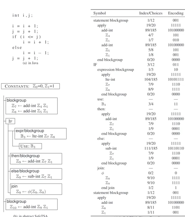
We also classify SafeTSA (which stands for Safe Typed Static Single Assignment Form) as a tree-oriented inter-mediate representation for mobile code, even though it is actually a hybrid format that combines high-level control structures in a AST-like form (called the Control Structure Tree) with individual instructions in static single assign-ment form [3, 70]. The format was designed as a drop-in replacement for Java Bytecode6 providing for more effi-cient just-in-time compilation and an innovative approach to safety based on aninherently safeencoding.
SafeTSA’s control structure tree provides for all of the non-linear intra-procedural control flow in SafeTSA. The instructions (which only perform computations, manipu-late data on the heap, and call methods) are embedded as leaves of the control structure tree with their execution being controlled by their parents in the tree. The high-level control structures provided by SafeTSA (which mir-ror those provided by the Java programming language), re-strict SafeTSA programs to reducible intra-procedural con-trol flow. They also make it possible to do a syntax directed derivation of the control flow graph and dominator tree, and also allow for the possibility of high-speed single-pass syntax-directed JIT compilation of SafeTSA code.
The primary driver of enhanced efficiency for just-in-time compilation of SafeTSA, however, results from the
6And, in fact, the prototype implementation of SafeTSA based on the Jikes Research Virtual Machine supports intermixing classes loaded from both SafeTSA and JVML class files within a single executing virtual ma-chine [4].
use of Static Single Assignment Form (SSA). Static Single Assignment Form guarantees that each instruction’s result variable is unique (i.e., assigned to at only that static loca-tion in the program) [14]; this discipline (which is facili-tated by specialφ-functions that merge alternative values that reach a program point on different control flow paths) enables a variety of optimizations that are now standard in state-of-the-art optimizing compilers. In SafeTSA, the use of SSA facilitates producer-side machine-independent op-timization and speeds up several consumer-side optimiza-tions. As reported in [4], the net result is that JIT compilers for SafeTSA can deliver the same quality code in less time than a JIT compiler for JVML.
Static single assignment form also plays a key part in SafeTSA’s inherently safe encoding. The binary on-the-wire SafeTSA is designed such that it only uses the num-ber of bits required to represent possible program symbols that might result in a syntactically valid and correctly typed program [70]. In this way, the program is more dense, be-cause it is not wasting bits that do not differentiate between correctly typed programs.
In addition, a separate verification phase is unnecessary, because the decoding process only ever produces syntac-tically valid and correctly typed programs. There are a couple of mechanisms that enable this. Perhaps the most important mechanism is the implicit naming and enumer-ation of variables according todominator scopingand the type separation. The implicit naming is based on the prop-erty that, in static single assignment form, each variable is only ever assigned at a single location, so by enumerating the locations where variables are created, one can create names for the variables. In static single assignment form, a variable is live at a program point, if and only if, its defin-ing instruction dominates that program point. Therefore, SafeTSA limits the scope of all SSA variables to the pro-gram region dominated by its definitions, and the implicit enumeration takes advantage of this so that variables are enumerated consecutively along the path of the dominator tree to the point the variable is being accessed.
In addition SafeTSA’s variable enumeration istype sep-arated. That is, there are no implicit coercions, so the vari-ables of each type can be enumerated independently. These mechanisms enable all symbols representing operands to be selected from a list of candidate operands that would be legal in that program location. Simpler mechanisms are used for symbols and other kinds of program elements, and a binary prefix code is generated for each position in the program based on an implicit enumeration of the possible alternative symbols for that position.
i n t i , j ;
i = i + 1 ; j = j + 1 ; i f ( i <= j )
i = i + 1 ; e l s e
i = i − 1 ;
j = j + 1 ; (a) in Java
CONSTANTS: Z0=0,Z1=1
blockgroup
Z7←add-intZ4Z1
Z8←add-intZ5Z1
IF
expr/blockgroup
B3←lte-intZ7Z8
USE:B3
then/blockgroup
Z9←add-intZ7Z1
else/blockgroup
Z9←sub-intZ7Z1
join
Z9←φ(Z9,Z9)
blockgroup
Z10←add-intZ9Z1
(b) in abstract SafeTSA
Symbol Index/Choices Encoding
statement blockgroup 1/12 001
apply 19/20 11111
add-int 89/185 10100000
Z4 4/7 101
Z1 1/7 010
add-int 89/185 10100000
Z5 5/8 101
Z1 1/8 001
end blockgroup 0/20 0000
IF 3/12 011
expression blockgroup 1/3 10
apply 19/20 11111
lte-int 104/185 10101111
Z7 7/9 1110
Z8 8/9 1111
end blockgroup 0/20 0000
use: — —
B3 3/4 11
then: — —
apply 19/20 11111
add-int 89/185 10100000
Z7 7/9 1110
Z1 1/9 0001
end blockgroup 0/20 0000
else: — —
apply 19/20 11111
sub-int 111/185 10110110
Z7 7/9 1110
Z1 1/9 0001
end blockgroup 0/20 0000
join: — —
φ 0/2 0
Z9 9/10 1111
Z9 9/10 1111
end join 1/2 1
statement blockgroup 1/12 001
apply 19/20 11111
add-int 89/185 10100000
Z8 8/11 1101
Z1 1/11 001
(c) in SafeTSA’s Binary Encoding
symbol representing the type (Zfor integer,Bfor boolean) and a subscript indicating the variables position in 0-based implicit enumerations. The integer constants, 0 and 1, are declared to be represented byZ0andZ1, respectively. The initial values of i and j are assumed to beZ4andZ5, and it is assumed that there are 7 integers and 2 booleans defined before the first instruction shown. With these assumptions, the first instruction in the first blockgroup adds 1 toZ4(i.e., the old i) and puts the result inZ7(i.e., the new i). Note that there are several definitions ofZ9, which appears to be a violation of the single assignment property, but none of these definitions dominates any of the others so their scopes do not overlap and they are distinct variables. In fact, this mechanism effectively prohibits accessing non-dominating variables, since their names get re-used by those that do dominate a particular access. Due to the peculiarities of φ-functions in SSA, the definition of the thirdZ9actually refers to the firstZ9and the second operand refers to the secondZ9, but according to SafeTSA’s rules [70], only the correctZ9is in scope at each of those positions. The ren-dering of the tree representation into a sequence of sym-bols, and the binary encoding of those symbols is shown in Figure 9(c).
3.3 Proof-annotated representations
In the past decade, there have been several research projects aiming at the development of certifying compilers. Cer-tifying compilers differ from traditional compilers in that in addition to producing executable code, they also pro-duce an additional annotation (i.e., a certificate) contain-ing a proof that the executable code respects certain safety properties (usually type and memory safety). The proof-annotated code format is designed so that all proofs can be automatically checked in a bounded amount of time. In a mobile code context, such a proof-annotated format can be used to only allow the execution of mobile code for which it is determined that the proofs are correct and that the proofs are sufficient to guarantee that the annotated code satisfies the safety properties required by the mobile code system.
Proof-Carrying Code [55] and Typed Assembly Lan-guage [51] are the two primary representatives of proof-annotated mobile code formats. As introduced by George Necula in 1996, proof-carrying code utilizes certificates written in a formalism based on first-order logic. This proof can be generated by the code producer and shipped along with the program code. The code consumer then validates the proof to ascertain the safety of the transmit-ted mobile code. Due to its foundation in first-order logic, proof-carrying code is quite flexible in terms of the types of safety properties that can be checked using first-order logic; the limiting factors on flexibility are the kinds of proper-ties for which proofs can be generated automatically. The Touchstone compiler7is the front-end of a prototype proof-carrying code system that compiles from a safe subset of
7A variant of Touchstone, called SpecialJ, has been developed for the Java programming language [10, 11].
the C programming language into machine code and cer-tifies that the resulting machine code is type and memory safe [55, 58].
Typed Assembly Language extends traditional untyped assembly languages with typing annotations, memory man-agement primitives, and a sound set of typing rules. These typing rules guarantee the memory safety, control flow safety, and type safety of the transmitted program.
3.3.1 Proof-carrying code
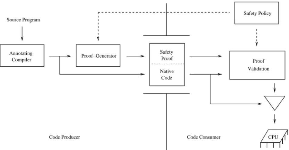
Proof-Carrying Code (PCC) was originally developed as a mechanism for safe operating system kernel extensions, but was later adapted to the area of mobile code [54, 56]. Founded on formal program verification theory, PCC al-lows the code consumer to check the safety of programs by checking machine-readable proofs that are generated by the code producer and shipped along with the program code. After checking the validity of the proofs, code consumers are then assured that the program execution will not vio-late the verified properties. The desired safety properties depend on the code consumers safety policy, which acts as a contract between the code producer and code consumer, and defines which conditions must be satisfied by safe mo-bile programs.
In a proof-carrying code system, the role of the code producer is fulfilled by a certifying compiler, consisting of an annotating compiler and a proof-generator. While the certifying compiler translates the program that is to be transmitted into machine code of the target platform or any other executable code representation, it also annotates the program with additional information (e.g., types) that would otherwise be lost. After this, a theorem (possibly-specialized) prover is used to generate a proof that the gen-erated code complies with the mobile code system’s safety policy, and this proof is transmitted along with the code to the code consumer in a PCC binary. The code consumer validates the safety proof based on the actual machine code and the conditions defined in the safety policy. The valida-tion algorithm and the safety policy are the only parts of the system which have to be trusted, minimizing the size of the trusted code base (TCB)8. If proof validation is successful, the safety of the transferred mobile program is guaranteed and the machine code can be executed as shown in Figure 10.
Safety conditions, which have to be satisfied by the transferred mobile code are defined within the safety pol-icy and are shared between code producer and code con-sumer. This safety policy is based on first-order logic and consists of three parts: a verification condition generator (VCG) [19], a set of axioms, and pre- and post-conditions. The verification condition generator is used to derive a safety predicate (i.e., a verification condition), from the an-notated program code. The safety predicate is derived such that it will only evaluate to true if every condition specified
CPU Safety
Proof
Code
Native Validation Safety Policy
Code Producer Code Consumer Source Program
Proof−Generator Compiler
Annotating
Proof
Figure 10: Proof-Carrying Code Architecture.
in the safety policy is satisfied. The pre- and post-condition included in the safety predicate, express constraints on the machine state that must hold, respectively, before and after program execution. The safety predicates, which are de-fined in first-order logic, are derived from a set of axioms and derivation rules that model the state transitions of the target machine associated with each instruction.
Both, code producer and code consumer, derive the safety predicate from the annotated program code. The code producer generates a proof of the safety predicate, indicating the safe execution of the program code, and the code consumer derives the safety predicate in order to check the matching of program code and safety proof. Thus, the verification condition generator traverses the pro-gram code and creates predicates for each critical instruc-tion (e.g., memory access) using a symbolic interpreter, such that a proof of these predicates ensures that execut-ing the correspondexecut-ing instruction does not invalidate the conditions defined in the safety policy.
To support complex program structures like method calls and loops, the verification condition generator uses invari-antsannotated in the program code. These annotations are frequently required to mark loop invariants, which cannot normally be automatically derived by the verification con-dition generator. The invariants are included among the predicates which must be verified. Thus, the code con-sumer does not need to trust the program annotations, and the invariants are only used as hints supporting the gener-ation, and the validation of the safety proof. These predi-cates must be proved to hold for every control path between two distinct invariants, starting with the pre-condition and finishing with the post-condition. As a consequence, the safety predicate of the whole program is the conjunction of all predicates derived from the invariants and the individual instructions.
After the safety predicate has been derived by the ver-ification condition generator, the code producer creates a proof, which shows the correctness of the generated safety predicate. This safety proof is represented using the
Edin-burgh Logical Framework or LF notation [42, 68]. The Ed-inburgh Logical Framework efficiently validates the proofs by reducing validation to a simple type-checking procedure [55, 57]. (In other words, in the Edinburgh Logical Frame-work, only correct proofs are correctly typed.) Thus, the code consumer of a PCC system can be guaranteed that a mobile code program satisfies its safety policy prior to its execution.
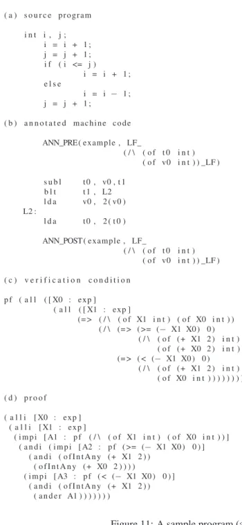
As a concrete example of a PCC system, let us exam-ine the output of the Touchstone certifying compiler. The Touchstone certifying compiler might translate the source program, shown in Figure 11 (a), into the slightly opti-mized DEC ALPHA assembly code as shown in Figure 11 (b). Note that a pre- and post-condition are annotated, both stating that registers v0 and t0, which represent vari-ables i, j of the source program respectively, contain integer values. In order to verify the safety of the machine code, the Touchstone certifying compiler generates a verification condition and a safety proof, indicating the validity of the verification condition. The verification condition, shown in Figure 11 (c), states type and memory safety of the ma-chine code. Therefore, the verification condition denotes the implication that: assuming the registers v0 and t0 hold integer values initially, their values after manipulation will still be of type integer after the machine code has been ex-ecuted. Thus, the post-condition can be derived from the pre-condition, and the validity of the verification condition is proven. The safety proof shown in Figure 11 (d) states the validity of the verification condition and therefore guar-antees type and memory safety of the machine code.
suc-( a ) s o u r c e program
i n t i , j ; i = i + 1 ; j = j + 1 ; i f ( i <= j )
i = i + 1 ; e l s e
i = i − 1 ; j = j + 1 ;
( b ) a n n o t a t e d machine code
ANN_PRE( example , LF_
( / \ ( o f t 0 i n t ) ( o f v0 i n t ) ) _LF )
s u b l t 0 , v0 , t 1 b l t t1 , L2 l d a v0 , 2 ( v0 ) L2 :
l d a t 0 , 2 ( t 0 )
ANN_POST( example , LF_
( / \ ( o f t 0 i n t ) ( o f v0 i n t ) ) _LF )
( c ) v e r i f i c a t i o n c o n d i t i o n
p f ( a l l ( [ X0 : exp ]
( a l l ( [ X1 : exp ]
(= > ( / \ ( o f X1 i n t ) ( o f X0 i n t ) ) ( / \ (= > ( >= (− X1 X0 ) 0 )
( / \ ( o f (+ X1 2 ) i n t ) ( o f (+ X0 2 ) i n t ) ) ) (= > ( < (− X1 X0 ) 0 )
( / \ ( o f (+ X1 2 ) i n t ) ( o f X0 i n t ) ) ) ) ) ) ) ) )
( d ) p r o o f
( a l l i [ X0 : exp ] ( a l l i [ X1 : exp ]
( i m p i [ A1 : p f ( / \ ( o f X1 i n t ) ( o f X0 i n t ) ) ] ( a n d i ( i m p i [ A2 : p f ( >= (− X1 X0 ) 0 ) ]
( a n d i ( o f I n t A n y (+ X1 2 ) ) ( o f I n t A n y (+ X0 2 ) ) ) )
( i m p i [ A3 : p f ( < (− X1 X0 ) 0 ) ] ( a n d i ( o f I n t A n y (+ X1 2 ) )
( a n d e r A1 ) ) ) ) ) ) )
Figure 11: A sample program (a) and its PCC output (b), (c) and (d).
cessfully verified. The second part of the Proof-Carrying Code binary contains a symbol-table, which is used to re-construct the LF representation of the safety proof on the consumer side. The last part includes the safety proof in a binary encoding.
3.3.2 Typed assembly language
The use of a Typed Assembly Language as intermediate representation benefits a mobile code system in several ways. First of all, a number of program optimizations are enhanced by having type information available in the as-sembly code. In addition, the type annotations facilitate
the verification of the mobile code’s type safety. In order to gain these benefits, a type abstraction of assembly lan-guages is required, which guarantees type safety of well-formed assembly programs and hence enables the transfor-mation of well-formed input programs into safe assembly code [38]. Since the type annotations and type checking, serves to prove that a program in a Typed Assembly Lan-guage is type safe, it can be considered as a kind of proof-annotated representation, even though the proof is not that of a direct assertion of safety in a general logic as it is in proof-carrying code [52].
(*.scm) (*.pop)
Scheme Compiler Popcorn Compiler
*.tal
...
*.tal Source Program
Source Program
Assembler
Machine Code
Code Consumer Code Producer
Type Checker
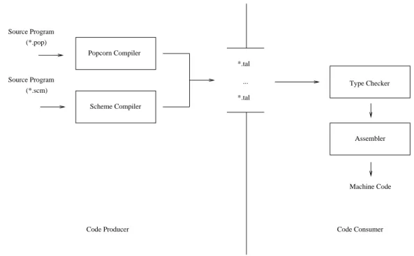
Figure 12: Talx86 system.
[36]. TALx86 incorporates support of the programming languages Scheme and Popcorn (a type-safe subset of the C language from which unsafe constructs such as pointer arithmetic and address operator have been removed). On the producer side of the prototype TALx86 system (see Figure 12), programs of the Scheme or Popcorn program-ming language are transformed into assembly code for the target platform, and the generated assembly code is anno-tated with type information resulting in Typed Assembly Language. After receiving a program, the code consumer uses the annotated type information to type-check the trans-ferred assembly program. If the mobile code is success-fully verified, an assembler transforms the assembly code into machine code for the target platform, which is then executed.
The TALx86 implementation is based on Microsoft’s Macro Assembler Language, and therefore, TALx86 pro-grams, after being type-checked, can be efficiently assem-bled with common commercial assemblers. Within the TALx86 system, the register-based Microsoft Macro As-sembler Language is extended with annotations, which are mainly used as pre-conditions of code labels, assigning type information to registers.
Our sample program (now written in Popcorn) in Figure 13 (a) and its translation into TALx86 are shown in Figure 13 (b). The TALx86 sequence consists of two sections: the assembly language instructions and its corresponding type annotations. The assembler program starts by calculating increments of values contained in registers EBP and EDI, which represent the variables i and j, respectively. Sub-sequently, the values are compared, and if the value con-tained in EBP exceeds the value in EDI, execution
contin-ues at the code label ifFalse$49, which represents the else branch of the program. Otherwise, the then branch of the if statement is executed, and the value contained in EBP is incremented. After that, program execution proceeds to the label ifMerge$50, which marks the end of the if statement, and the value in register EDI is incremented again.
Both labels are annotated with the types of values con-tained in the registers at that point. As an example, an-notation EDI:B4 denotes type B4 in register EDI, indi-cating a 4-byte integer value inside. On the consumer side, the annotation is then used by the type-checker, so that it only has to check that the register EDI contains a value of type B4 before control is given to label ifFalse$49 or ifMerge$50 (rather than propagating types around the control-flow graph until a fixed pointer is reached or a type error is detected).
Polymorphic types, required for describing high-order structures like stacks, are realized using placeholders, which are replaced by corresponding types before control is transferred to the associated code label. Type annota-tions are also used to define new types with type construc-tor declarations. This flexibility of the type system allows one to support a wide range of programming languages. TALx86 allows the code consumer to provide routines of instructions (i.e., macros) for manipulating complex data structures that can be typed and treated as atomic opera-tions during verification. Programs may explicitly allocate such complex data structures using the macro malloc but are not allowed to explicitly de-allocate the structures; this is done implicitly, through garbage collection.
( a ) i n t i , j ; i = i + 1 ; j = j + 1 ; i f ( i <= j )
i = i + 1 ; e l s e
i = i − 1 ; j = j + 1 ;
( b ) MOV EDX, EBP ADD EDX, 1 MOV EBP , EDX MOV ESI , EDI ADD ESI , 1 MOV EDI , ESI CMP EDX, ESI
JG t a p p ( i f F a l s e $ 4 9 , < r$9 >) ADD EBP , 1
JMP t a p p ( i f M e r g e $ 5 0 , < r$9 >) i f F a l s e $ 4 9 :
LABELTYPE < A l l [ r $ 9 : Ts ] . { EDI : B4 , EBP : B4 , ESP : s p t r {ESP : s p t r r $ 9 } : : r $ 9 }> MOV ESI , EBP
SUB ESI , 1 MOV EBP , ESI FALLTHRU < r$9 > i f M e r g e $ 5 0 :
LABELTYPE < A l l [ r $ 9 : Ts ] . { EDI : B4 , EBP : B4 , ESP : s p t r {ESP : s p t r r $ 9 } : : r $ 9 }> ADD EDI , 1
Figure 13: Sample program in Popcorn (a) and corresponding TALx86 program (b).
consisting of a top-most element of type t and the rest of the stack described by s. Placeholders are applied in order to enable the polymorphic representation of stacks. A place-holder is of a general form All[s:Ts] where Ts denotes the abstract type, which is substituted by a corresponding in-stance s.
As a consequence, function calls are represented by the help of a runtime stack s, which is referenced by stack pointer sptr s contained in register ESP. This can bee seen at labels ifFalse$49 and ifMerge$50 of Figure 13 (b), where register ESP references the runtime stack, which contains another stack pointer representing the caller frame, and the rest of the stack denoted by the polymorphic type r$9.
Polymorphic types in combination with runtime stacks are also used to implement visibility rules, which make the actual representation of abstract types associated to local variables only resolvable by the authorized function. Fur-thermore, this mechanism supports exception handling by restricting register access. A dedicated register contains a stack pointer which indicates where to unwind the runtime stack to. This stack pointer is typed so that it is abstract and therefore unmodifiable by everything except for the excep-tion code.
The time-critical processes in the TAL system include the code consumer’s type-checking and the transfer of the mobile program to the code consumer. Thus, a compact en-coding of Typed Assembly Language is needed for optimal performance. Since the annotations (e.g., pre-conditions of code-labels) increase the code size, various compression techniques can be applied to increase the density of the
an-notation format, so that it is more suitable for mobile code [37]. These techniques include, among other, the sharing of common sub-terms within annotations, the use of generic type abbreviations, and the elimination of unnecessary an-notations.
4 Review and comparison
In the following sections, the mobile code representations that were presented earlier will be evaluated according to the requirements introduced in Section 2. Table 1 sum-marizes this evaluation and can be used as a guide to the discussion that follows.