26
Simulation Study on the Effect of
Asymmetric Fin Position on
Aerodynamic Characteristic of a Missile
Wan Khairuddin Wan Ali, a,* Mohamad Hafiz Shafie, a
a, Faculty of Mechanical Engineering, Universiti Teknologi Malaysia, 81310 UTM Skudai, Johor, Malaysia.
*Corresponding author: [email protected]
Abstract
The aerodynamics controlling performance of a missile depends a lot on its fins and their configurations. When the fins location is moved forward from its original position, the force moment acting on the missile will change. One of the difficulties faced by missile designers is to determine the optimum fins location. This paper presents a study on the effect of asymmetric fins location on aerodynamic characteristic of a missile. The study was done using Ansys Workbench 14.Two opposite fins were moved forward from their original positions to three locations; i.e. 4cm, 8cm and 12cm. The simulation started with 0o angle of attack until 22.5o with 2.5o increment for every angle. In Ansys 14, the turbulence Spalart Almaras model with one equation was chosen. The result from this study shows that the aerodynamic performance of the missile was affected by the changing of fins position. The best fins locations for a missile were found to be at two locations, 7.9cm or 10.1cm from its actual position.
Keywords: Missile, Aerodynamic Characteristic, Fins performance, Missile Simulation
1.INTRODUCTION
One of the activities in missiles design involves predicting the aerodynamic controlling performance. Most missiles use fins as the major element to control their flying trajectories. The problem arises when attaching fins to a missile body is that they will add force moments [1, 2]. Without a proper study, these force moments may lead to flight instability that could lead to disastrous consequence. In missile control situation, it is desirable to have the effect of these force moments only when needed, and the effect should be zero in a free flight condition. The objective of this study was to find the effect of asymmetric fin position on aerodynamic characteristic of a missile based on computer simulation. The fins on a missile will
strongly influence the stability and manoeuvrability of missile to acquire its flight trajectory to hit the target. The study was conducted using numerical aerodynamic test, or known as Computational Fluid Dynamic (CFD).
27
missile can make the bomb statically stable. Spin can cause the average angle of attack to be much lower, and reduce the drag [3].
In this study, missile moment coefficient was the most important parameter needed to be determined. A graph of moment coefficient against angle of attack of the missile had been analyzed, which will be discussed in the next section.
2.METHODOLOGY
The basic principle of this study was to move forward two apposite fins of an existing missile called Tedung Kilat, from their original position to a specific distance. Different fin location produced different models. Four models were developed, and each of them was simulated in a wind tunnel conditions starting from angle of attack equal to 0o until 22.5o with 2.5o increment for every angle. The models were named as Symmetric Model, Model 1 (M1), Model 2 (M2) and Model 3 (M3) with fin forward placement being 0cm, 4cm, 8cm and 12cm, respectively. In Ansys 14, the turbulence Spalart Almaras model with one equation was chosen to analyze the missile simulation. Spalart Almaras is a one equation model that solves the empirical transport equation for eddy viscosity. One advantage of this model is its simplicity with which the free stream and the wall boundary condition can be levied [4].
In any missile design, wind tunnel testing is done after computer simulation has produced optimum missile dimensions and a missile model has been fabricated. The computer simulation should simulate the missile flying in a free space condition as well as in the wind tunnel. For a sizeable wind tunnel like UTM Low Speed Wind Tunnel (UTM-LST) in comparison with the actual dimension of the simulated missile, the wind tunnel result should be able to sufficiently predict the true free space flying conditions [5-6]. Therefore, the computer simulation in this study focused on simulating the missile flying in the wind tunnel environment. The medium for the main boundary condition for this study was defined as fluid, which means that the air should move smoothly from the inlet of wind tunnel to exit of wind tunnel. The wall of the wind tunnel and the missile body surface were defined as solid boundary condition where no fluid can pass
through. However, the most critical part was at the inlet of the wind tunnel. The velocity of air flow needed to be defined accurately. Since the maximum speed of UTM-LST is about 80m/s, the velocity of air at inlet boundary was set to 77m/s, which was lowered only a bit compared from the maximum value to add some margin of safety. The graphs of lift, drag and moment coefficient were obtained from this CFD simulation. Table 1 shows the mesh sizing used in the simulation.
Table 1. Local Mesh Condition Setting
Condition Face
Sizing
Face Sizing 2
Face Sizing 3
Part Missile
Body
Fins Edge
FinT Edge
Element Size (m)
0.003 0.0005 0.001
Curvature Angle (°)
60 60 60
Growth Rate 1.15 1.16 1.16
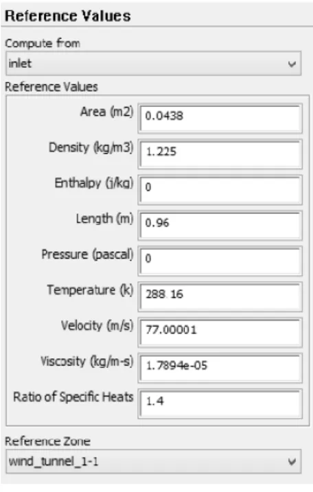
Table 2 shows a list of reference value set for the simulation.
Table 2. Reference Values for Simulation.
3.VALIDATIONMETHODANDRESULT
28
missiles dimension. The overall length of UTM X1 missile is longer than Tedung Kilat. The nose cone of each missile is also different. Figure 2 shows the comparison of the data from this study and previous wind tunnel test for UTM X1. The graph shows that Tedung Kilat missile had more drag compared to UTM X1 at most angles of attack. However, at angle of attack 0o to 7.5o, the drag coefficient did not show much difference.
Figure 1. Comparison between UTM X1 and Tedung Kilat
Figure 1 shows the bigger frontal area of Tedung Kilat compared to UTM X1 since the body diameter of Tedung Kilat and UTM X1 are 80mm and 70 mm, respectively. Therefore, more drag force from air inlet acted on Tedung Kilat than UTM X1. The missile configuration for both Tedung Kilat and UTM X1 are also different. Tedung Kilat has an ogive nose cone while UTM X1 rocket has a sharp nose cone. Moreover, in length, Tedung Kilat is shorter than UTM X1 rocket. Because of these factors, the missile has slightly different aerodynamic properties in drag force.
Figure 2. Comparison between Exp. UTM X1 and CFD Symmetry Model
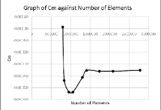
Figure 3 shows the graph of Cm against the number of elements in this grid stabilization study. The value of moment coefficient would fluctuate if the number of elements was less than 1.5 million. The Cm stabilized after 1.5million number of element. After that, the values remained constant even at the final tested number of elements of about 2.75million. The graph shows that to obtain an accurate data of moment coefficient in simulation, the minimum number of elements for meshing should be 1.6 million. However, by using the number of elements greater than 1.6 million, the simulation took longer time to complete the calculation. Therefore, 1.6 million of mesh elements was chosen as the number of elements needed to be used in this work.
Figure 3. Cm stabilized after 16million number of elements used
4.SIMULATIONRESULTANDDISCUSSION
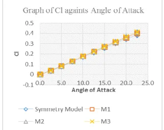
The simulation data focused on three aerodynamic parameters that govern the manoeuvrability and control performance of a missile, namely lift coefficient (Cl), drag coefficient (Cd) and moment coefficient (Cm).
29
This is the reason for the similarities in lift coefficient for all of Tedung Kilat models.
Figure 4. Cl remains unchanged for all models tested
The second parameter analyzed was moment coefficient. In a controlled flight, force moment plays a major role to provide the necessary turning force for the missile.
Figure 5. Graph of Cm variation against Angle of Attack
Figure 5 shows the graph of moment coefficient against angle of attack. The moment coefficient characteristics for all models were different. Model 1 showed the highest negative moment coefficient change against the increasing angle of attack. Meanwhile, the moment change for Model 2 was almost zero. On the other hand, for Symmetry Model and Model 3, the Cm data have only slightly negative moment curve slope. From this, Model 1 should give the most negative moment to missile when cruising and as a result, Model 1 had the shortest cruising range. However, from the same graph, Model 2 showed the best moment
characteristic compared to other models because its overall moment coefficient was almost zero. There was just a small magnitude of additional moment acting on it even though with increasing angle of attack.
Another way of analyzing the effect of fin asymmetric is to determine the value of Cm at each angle of attack while varying the fins’ asymmetric distance. Figure 6 shows the moment coefficient graph against the asymmetric distance of fins’ position from their original location. The lines represent the different angles of attack.
Figure 6. The optimum fin locations at 7.9cm and 10.1cm
The graph shows that there were two locations where Cm was insensitive to the angle of attack, and this can be considered as the optimum fin location for controlling the missile. A non-turning fin or straight fin at this optimum position will not create any moment that can change the missile flying trajectory. It will create the turning moment (either yaw or pitch moment) only when the fin itself is turned.
It was found that the optimum Tedung Kilat fins positions were at distance of 7.9cm or 10.1cm from its original position. At these locations, the moment was zero for all angles of attack. It means that, the moment acting on the missile was very small when the fins were at these two points. As before, the lift and drag coefficient for all models were almost similar. The effect of lift and drag force to these
-3.00 -2.50 -2.00 -1.50 -1.00 -0.50 0.00 0.50
0 1 2 3 4 5 6 7 8 9 10 11 12 13
Cm
Distance,X (cm)
Graph of Cm againts Distance
30
models did not affect the missile cruising performance although fins locations were changed. Thus, the only aerodynamic parameter that affected the missile cruising performance was force moment.
It can also be said that by moving two opposite missile fins forward by 7.9cm or 10.1cm, the Tedung Kilat missile are expected able to cruise in longer range compared to its original model. Moreover, the missile manoeuvrability will also enhance since the missile can turn effectively without much impact from the force moment. Therefore, from this study, Tedung Kilat missile manoeuvre performance can be improved by relocating its two opposite fin to these locations.
5. CONCLUSION
This paper presents a simulation study on Tedung Kilat missile regarding the effect of asymmetric fin position on aerodynamic characteristic. It was found that for a relatively small missile as Tedung Kilat, the optimum number of mesh required should be 1.6 million for simulation in wind tunnel condition.
Positioning the opposite fins asymmetrically did significantly affect Cm but not both Cl and Cd. It is possible to find optimum positions to place the fin as the Cm of fin is zero at all angles of attack. For Tedung Kilat, the position is either at distance of 7.9cm or 10.1cm from its original position.
These values can pave the way for the fabrication of a wind tunnel model for further study.
6. ACKNOWLEDGMENT
The authors would like to thank the staffs of Aeronautical Laboratory, Universiti Teknologi Malaysia for their help in allowing using the advance computing facility at their premise.
7. REFERENCE
[1]Daniel J. Lesieutre, Marnix F. E Dillenius, Teresa O.
Lesieutre (1996) High Angle Of Attack Missile Aerodynamic Including Rotational Rates –Program, Nielsen Engineering & Research Inc, Mountain View Calirfornia 94043-2212 USA.
[2]Daniel J. Lesieutre, Marnix F. E Dillenius, Teresa O.
Lesieutre (1998). Missile Fin Planform Optimization
For Improved Performance, Nielsen Engineering & Research Inc, Mountain View Calirfornia 94043-2212 USA.
[3]Ralph D. Lorenze (2006). Spinning Flight Dynamic
of Frisbees, Boomerangs, Samaras, and Skipping Stones, University of Arizona, Springer,
[4]Muhammad Multazam b Abd Rahim (2012). A CFD
Study On an Aerofoil with Control Surface
Modification, Undergraduate Dissertation,
Department of Mechanical (Aeronautic), Universiti Teknologi Malaysia.
[5]J.B. Barlow, W.H. Rae, A. Pope (1999). Low-Speed
Wind Tunnel Testing, Third Edition, Jonh Wiley & Son, USA.
[6]Department of the Airforce (Author) and C.T. Myers