Limitation of Minimal Excitation Current by Load Angle Regulation
Tomislav Idzotic
1), Gorislav Erceg
2), Damir Sumina
3) Faculty of Electrical Engineering and ComputingUnska 3, Zagreb, Croatia Tel. / Fax: + (385 1) 6129-999/ 6129-705
1)[email protected], 2)[email protected], 3)[email protected]
Abstract - A synchronous generator connected to an AC system in capacitive operating mode is near its stability limit. In such conditions, if some disturbances in the system appear, a synchronous generator could lose the synchronism. The classical solution of this problem is to keep a generator in stabile operating range of P-Q diagram by limiting the minimal excitation current. This article analysis impact of additional control algorithms which are included in classical excitation regulation system with the purposes of keeping a generator in synchronism when some disturbances appear and generator is near its stability limit. These control algorithms include load angle estimation by corresponding P-Q diagram and load angle regulator which task is to keep the load angle of a synchronous generator operating in capacitive mode on the reference value so that generator remains in synchronism.
I. INTRODUCTION.
A synchronous generator which is connected to an AC system has to remain in synchronism even in some extreme situations that can appear in the operating conditions keeping a generator in the range of permissible loading. In the real system, the exceeding of allowed loading would cause the activation of generator protection and disconnection of a synchronous generator from an AC system. The voltage regulators of synchronous generators have the excitation current limitations as it is dictated by P-Q diagram (fig. 1.). This enables optimal utilization of the permissible loading and safer work of a generator that is operating in parallel with a distribution network.
Fig. 1. P-Q diagram of a synchronous generator including all limitations Under-excitation (capacitive) operating mode of a synchronous generator is appeared in systems with under-loaded long power transmission lines, by connecting long power transmission lines to voltage and by asynchronous work of regulating transformer regulators. Minimal limits
of the excitation current, limit the load angle and a generator will not lose synchronism. These minimal limitations in excitation current can be done based on P-Q diagram of a synchronous generator or by load angle regulation in under-excitation operating mode. These papers present minimal limitation of the excitation current based on the load angle regulation.
Presented solution in classical regulation structure, in which the voltage regulator is superior to excitation current regulator, includes the load angle regulator. When load angle is near its unstable value, the voltage regulator is turned off and the load angle regulator is turned on until load angle is decreased. In this situation load angle regulator sets the excitation current reference to its maximal value and on that way decreases the load angle so that generator remains in synchronism. So this regulation method enables stabile work of generator near the stability limits and expands the operating range of generator. The load angle estimation is based on voltage and current measurement of a synchronous generator. By load angle estimation is avoided additional sensor.
II. THE EXCITATION REGULATION STRUCTURE OF A SYNCHRONOUS GENERATOR
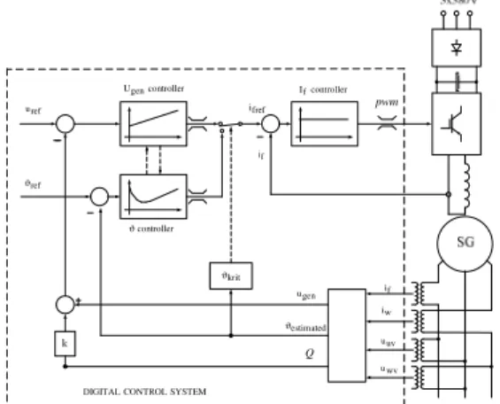
The excitation regulation structure with load angle estimation and additional load angle regulator is presented on the fig. 2.
Fig. 2. The excitation regulation structure of a synchronous generator with load angle estimation and additional load angle regulator According to the simulation results it is chosen PID regulator. Proportional and derivative part of the PID regulator determine the system response during start up and
SYSTEM CONTROL DIGITAL ref ϑ fref i f i Q pwm estimated ϑ krit ϑ f i w i uv u wv u gen u ref u controller gen U Ifcontroller controller ϑ
integral part assures that the load angle is equal to its wanted reference value in static operating conditions. In the moment of turning off the voltage regulator and turning on the load angle regulator the state of the integrator of the voltage regulator is written into the integrator of the load angle regulator. So this transition between two regulators is smooth and there is no unwanted step in excitation current reference.
III. MEASUREMENT AND ESTIMATION OF THE LOAD ANGLE OF A SYNCHRONOUS GENERATOR For load angle estimation is used voltage-current vector diagram (fig. 3.). ϑ ϕ U I ) X X ( I⋅ q− d 0 E I⋅Xq
Fig. 3. Vector diagram From diagram on the fig. 3. is obtained:
ϕ ⋅ ⋅ + ϕ ⋅ ⋅ + ϕ ⋅ ⋅ − ϕ ⋅ ⋅ = ϑ cos R I sin q X I U sin R I cos q X I tg
(1)
respectively P R I Q q X I S U Q R I P q X I arctg ⋅ ⋅ + ⋅ ⋅ + ⋅ ⋅ ⋅ − ⋅ ⋅ = ϑ.
(2)
Quadrature-axis synchronous reactance Xq is needed for this estimation method. Its value is well known from the producers and is not very dependent on saturation.
In situations when short circuit appears, generator voltage suddenly falls and generator current rises. In such situations, measuring equipment goes to saturation, and the measured results of active and reactive power are not reliable. The estimated value for load angle is not correct too. In such cases, the system forces the excitation current. The excitation current rises to its maximal value that is determined by its maximal limit. When short circuit appears, the load angle estimator sets the load angle to its maximal value and force the excitation current to its maximum limit. The load angle estimation algorithm is implemented in the developed digital system DIRES 21 [2] (fig. 4.).
IV. EXPERIMENT
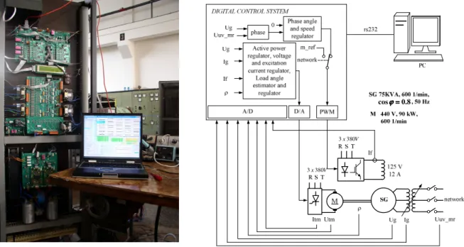
Experimental verification of the excitation regulation system of a synchronous generator is made on the laboratory model of the aggregate (fig. 5.). Digital excitation regulation system includes four DSPs ADMC300 [2]. The excitation winding of a synchronous generator is fed by IGBT converter.
Fig. 5. Digital regulation system and laboratory model of the aggregate The analysis is made with and without load angle regulator
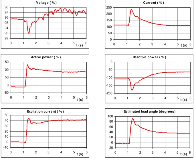
on the step change of the prime mover moment of the aggregate. Experimental responses of the excitation system of the synchronous generator operating in capacitive mode (capacitive loading Q=0.8 pu of the nominal power) on the
step change of active power P=1.0 pu without load angle regulator are shown on the fig. 6. In this case the generator loses the synchronism. When load angle regulator is included in excitation system the generator remains in synchronism (fig. 7.). V x380 3 V x380 3 8 . 0 cosϕϕϕϕ==== Voltage ( % ) 90 92 94 96 98 0 1 2 3 4 5 6 t (s) Current ( % ) 0 50 100 150 200 250 300 350 0 1 2 3 4 5 6 t (s) Active pow er ( % ) -50 0 50 100 150 200 0 1 2 3 4 5 6 t (s) Reactive pow er ( % ) -250 -200 -150 -100 -50 0 0 1 2 3 4 5 6 t (s)
Fig. 6. Experimental responses on the step change of moment without load angle regulator and Q=0.8 pu
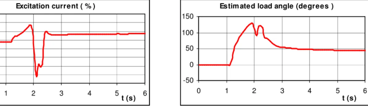
Fig. 7. Experimental responses on the step change of moment with load angle regulator and Q=0.8 pu (cap) Maximal load angle value is 70 º el. Even when the voltage
regulator reference is set to zero, the generator remains in synchronism during step change of active power P=1.0 (fig. 8.). Excitation current ( % ) -80 -60 -40 -200 20 40 60 80 0 1 2 3 4 t (s)5 6
Estimated load angle (degrees )
-50 0 50 100 150 0 1 2 3 4 5 6 t (s) Voltage ( % ) 95 95,5 96 96,5 97 97,5 98 98,5 0 1 2 3 4 t (s)5 6 Current ( % ) 0 50 100 150 200 250 0 1 2 3 4 t (s)5 6 Active pow er ( % ) -50 0 50 100 150 0 1 2 3 4 5 6 t (s) Reactive power ( % ) -150 -100 -50 0 0 1 2 3 4 t (s)5 6 Excitation current ( % ) 0 10 20 30 40 50 0 1 2 3 4 5 6 t (s)
Estimated load angle (degrees )
-20 0 20 40 60 80 0 1 2 3 4 t (s)5 6
Fig. 8. Experimental responses on the step change of moment with voltage regulator reference equal to zero
V. CONCLUSIONS
Presented experimental results show positive performance of the load angle regulator, which is added in classical excitation regulation system, on the stability of a synchronous generator in static as well as in dynamic operating conditions. In static operating conditions with increased active power, load angle regulator keeps the load angle on its reference value so that generator remains in stabile operating range. In dynamic operating conditions load angle regulator quickly increases the excitation current of a synchronous generator and on that way improve the stability of a synchronous generator which is connected to an AC system. Load angle regulator added in classical excitation system improves the stability of a synchronous generator in capacitive operating mode.
SYMBOLS
ϑ - load angle of a synchronous generator Xd , Xq – reactances of a synchronous generator R – armature resistance of a synchronous generator P – active power of a synchronous generator Q – reactive power of a synchronous generator S – apparent power of a synchronous generator U, I – voltage and current of a synchronous generator
ϕ - phase angle
REFERENCES
[1] Analog Devices, ADSP-2100 Family User´s Manual, Analog Devices Inc , Third Edition, 1995
[2] Erceg G., Idzotic T., Tonkovic N., "Digital Control System of a Synchronous Generator", EPE-PEMC, 2002.
[3] Erceg G., Idzotic T., Tonkovic N., "Hydro generating unit digital control system, Hydro, 2003.
Voltage ( % ) 92 93 94 95 96 97 98 0 1 2 3 4 5 6 t (s) Current ( % ) 0 50 100 150 200 250 0 1 2 3 4 t (s)5 6 Active pow er ( % ) -50 0 50 100 150 0 1 2 3 4 5 6 t (s) Reactive pow er ( % ) -200 -150 -100 -50 0 0 1 2 3 4 t (s)5 6 Excitation current ( % ) -10 0 10 20 30 40 50 0 1 2 3 4 t (s)5 6
Estimated load angle (degrees)
-20 0 20 40 60 80 100 0 1 2 3 4 t (s)5 6
[4] Girgis G.K., Vu H.D., “Verification of limiter performance in modern excitation control systems”, IEEE Trans. on Energy Conversion, Vol. 10, No. 3, 1995.
[5] Eberly T.W., Schaefer R.C., “Minimum/maximum excitation limiter performance goals for small generation”, IEEE Trans. on Energy Conversion, Vol. 10, No. 4, 1995.
[6] Ramos A.J.P., Lins L.R., Fittipaldi E.H.D., Monteath L., “Performance of under excitation limiter of synchronous machines for system critical disturbances”, IEEE Trans. on Power Systems, Vol. 12, No. 4, 1997.
[7] Working group of the excitation systems subcommittee, “Underexcitation limiter models for power system stability studies”, IEEE Trans. on Energy Conversion, Vol. 10, No. 3, 1995.