GLOBALIZING INTERNET SECURITY WITH A DISTRIBUTED FIREWALL AND ACTIVE RESPONSE ARCHITECTURE
A Thesis Proposal Presented to The Academic Faculty
by Lane Thames
In Partial Fulfillment of the Requirements for the Degree
Doctor of Philosophy in the
School of Electrical and Computer Engineering
Georgia Institute of Technology April 2008
GLOBALIZING INTERNET SECURITY WITH A DISTRIBUTED FIREWALL AND ACTIVE RESPONSE ARCHITECTURE
Approved by:
Randal Abler, Advisor
School of Electrical and Computer Engineering Georgia Institute of Technology
Henry Owen
School of Electrical and Computer Engineering Georgia Institute of Technology
George Riley
School of Electrical and Computer Engineering Georgia Institute of Technology
TABLE OF CONTENTS
LIST OF TABLES . . . v
LIST OF FIGURES . . . vi
SECTION 1 I INTRODUCTION . . . 2
II ORIGIN AND HISTORY OF THE PROBLEM . . . 5
2.1 Distributed Firewalls . . . 5
2.2 The DIADEM Firewall . . . 7
2.3 The Firewall Network System . . . 8
2.4 Cascade of Distributed and Cooperating Firewalls . . . 10
2.5 Cooperating Autonomous Detection Systems . . . 12
2.6 The Cooperative Intrusion Traceback and Response Architecture . . . 12
2.7 Event Monitoring Enabling Responses to Anomalous Live Disturbances . 14 2.8 Discussion of Related Work . . . 16
III PRELIMINARY RESEARCH . . . 17
3.1 Motivation . . . 17
3.2 The Firewall Collaboration Framework . . . 17
3.2.1 Experimental Evaluation of the FCF . . . 19
3.3 The Distributed Firewall and Active Response Architecture . . . 20
3.3.1 High-level Architectural Description . . . 21
3.3.2 Detailed Architectural Description . . . 23
3.3.3 Complexities of the Architecture . . . 27
3.3.4 Solutions for the Complexities . . . 29
3.3.5 Case Study–Using the Distributed Firewall and Active Response Architecture to Prevent the SSH Dictionary Attack. . . 32
3.3.6 Summary . . . 35
IV PUBLICATIONS . . . 36
4.1 Conference Papers . . . 36
SECTION 2
V PROPOSED RESEARCH . . . 38
5.1 Expected Dissertation Title . . . 38
5.2 Dissertation Abstract . . . 38
VI WORK REMAINING TO BE DONE . . . 40
VII EXPECTED CONTRIBUTIONS . . . 43
VIII FACILITIES NEEDED . . . 44
LIST OF TABLES
LIST OF FIGURES
1 The FCF Functional Components . . . 18
2 A Trusted Domain of Administration . . . 22
3 The Distributed Firewall and Active Response Architecture . . . 23
4 Experimental Results of Firewall Service Time as a Function of N . . . 28
5 SSH Dictionary Attacks Against an Internet Server . . . 33
6 Number of Unique IP Addresses Attacking the Server . . . 33
CHAPTER I
INTRODUCTION
The Internet, one of the largest engineered systems ever deployed, has become a crucial tech-nology for our society. It has changed the way people perform many of their daily activities from both a personal perspective and a business perspective. Unfortunately, there are risks involved when one uses the Internet. Risks that threaten the availability and security of computers, applications, information, and networks are the result of vulnerabilities that can be exploited in operating systems, software systems, and networking equipment. These risks coupled with advanced and evolving attack techniques place heavy burdens on security researchers and practitioners while trying to secure their networking infrastructures.
Technologies exist that can protect our computational infrastructures. Common tech-nologies deployed for security purposes include anti-virus software, cryptographic software, intrusion detection systems, and firewalls. The prevalence of these different types of security technologies reveal the current paradigm of deploying security with layered solutions, also referred to as “Defense in Depth” security.
The firewall is an extremely effective device that is used to protect computers and networks from unauthorized access. It is a device that allows or denies network connections to or from an entity based on the entity’s security policy. The security policy is a set of statements that define legal network operations for the entity. A firewall can be either host-based or network-host-based. A host-host-based firewall is normally implemented with software that is installed on the end host. The network-based firewall is a dedicated device placed within an enterprise’s network. These network-based firewalls are often placed at the network’s ingress and egress locations, and these ingress/egress firewalls are called perimeter firewalls. The classical assumptions that are used when designing perimeter firewall systems constitute the following two principles:
controls all ingress and egress points within the network. Firewalls are placed in-line at all defined ingress/egress points, and these firewalls create perimeters such that one can define inward and outward network traffic flows and associated access specifications.
• All users within the inside perimeter are assumed to be trusted.
These two principles can no longer be used when designing secure networks with perimeter firewalls. First, ingress/egress points can be established without the knowledge or control of the network administrator because of the wide availability of broadband access. It is trivial for end users within the inside perimeter of a network to create personal wireless local area networks or to establish Internet connections using Digital Subscriber Line (DSL), cable, dial-up modem, or broadband over cellular technologies. Because of these situations, it is impossible for the network administrator to completely define all network ingress/egress locations within the enterprise. Second, inside users can issue computer attacks on other inside users. Therefore, complete insider trust can not be assumed. Host-based firewalls have become ubiquitous, partially due to the limitations of the perimeter firewall. With a host-based firewall, there is no need to consider perimeters and network topologies be-cause the perimeter exists at the host’s network interface. Further, the host does not have to assume trust to any other machine within the local network. Another problem with perimeter firewalls is due to complex network topologies. Complex network topology makes the configuration of perimeter firewalls difficult for security administrators.
A general shortcoming of any firewall is due to its quasi-static security policy configura-tion. The security policy enforced by a firewall remains constant unless there is an explicit need to change the policy. Generic firewalls cannot adapt to real-time threats and attacks unless the administrator takes appropriate measures and applies new policies that target the attacks. A solution that allows the firewall to dynamically update its security policy during the event of an attack can increase the security provided by the firewall. Distributed firewalls have been proposed [5, 6, 10, 27, 33] as solutions to the shortcomings of classi-cal firewalls. These distributed solutions can be categorized as systems that use defense
in depth strategies or systems that use centrally defined security policies with end-point enforcement.
Intrusion detection is technology that provides intrusion detection and attack detection capabilities [4, 15, 29]. Classically, an Intrusion Detection System (IDS) incorporates a central monitoring agent and a system of sensors distributed throughout the network. Using sophisticated algorithms, the sensors detect intrusive behavior and send relevant detection information back to the central monitor. Then, the central monitor sends an alert to the security administrator, and the task of acting on the alert is the responsibility of the administrator. This reveals the reactive security model that is currently used by security administrators. The administrator can act on the alerts by configuring policies within a firewall system that counter the effects of an attack. However, malicious users, also known as hackers, continue to develop more sophisticated network attack techniques. These advanced attack techniques have increased the risk imposed by the delay between attack detection and human response time. The time needed for a human administrator to create and configure security policies related to attack alerts is too large for modern day attacks. As a result, research is being pursued in the area of active response [9, 17, 28]. Active response relies on technology that deploys defensive mechanisms without the need for human advisory when intrusive behavior is detected within a network system.
Intrusive behavior and computer attacks can be detected with intrusion detection sys-tems, and firewalls can prevent unauthorized access to information and computational re-sources. However, these devices normally function independently from one another. An architecture that provides the capabilities for allowing these technologies to work coopera-tively would improve our existing network security framework. Therefore, the objective of the research proposed in this paper is to study a distributed firewall and active response architecture that bridges the gap between attack detection systems, firewalls, and active response such that preemptive protection can be provided as a result of the cooperation between attack detection systems and firewalls. The goal of this research is to introduce a security mechanism that provides a shift from our current reactive security model to a more robustpreemptive security model.
CHAPTER II
ORIGIN AND HISTORY OF THE PROBLEM
Perimeter firewalls have several shortcomings. First, it is hard to design perimeter firewall systems for complex network topologies. Second, complete insider trust must be assumed for users on the internal network because the perimeter firewall cannot monitor the network traffic flowing between internal hosts. Third, perimeter firewalls are placed in-line at the networks ingress and egress locations. Therefore, the perimeter firewall can become a traf-fic bottleneck for the network. Fourth, certain protocols such as the File Transfer Protocol (FTP) are hard to process at the perimeter firewall because of dynamic transport layer port assignments. Finally, perimeter firewalls cannot inspect encrypted payloads. Distributed firewall systems have been proposed as solutions to some of these limitations. The objec-tive of the research proposed in this paper is to study the effects of distributed firewalls that cooperate with intrusion (or attack) detection systems such that active response can be achieved. Therefore, a review of previous work in distributed firewalls and intrusion detection was conducted. The first part of this chapter will discuss previous work in the area of distributed firewalls. Then, a discussion of related work in intrusion detection and active response systems will follow.
2.1 Distributed Firewalls
One of the first discussions of distributed firewalls was given by Bellovin [5, 10]. Perimeter firewalls are designed with the concept of an inside and outside interface. Hosts within the network that are connected to the inside interface are assumed to be trusted. All hosts connecting from networks on the outside interface are assumed to be untrustworthy and potentially dangerous. Incoming and outgoing network traffic must flow through the perimeter firewall and only traffic that conforms to the firewall’s security policy will be allowed. Bellovin proposed the distributed firewall as a replacement of the perimeter firewall because of several perimeter firewall shortcomings:
• It is hard to design perimeter firewall systems for complex network topologies.
• Complete insider trust can not be assumed.
• Perimeter firewalls are network bottlenecks.
• Certain protocols are difficult to process at the perimeter firewall.
• Encrypted payloads cannot be inspected by the perimeter firewall.
Conventional perimeter firewalls enforce an enterprise’s security policy at the ingress/egress points of the network. In Bellovin’s solution, the security policy is centrally defined, but enforcement is implemented at end-point hosts within the network by way of using host-based firewalls. One should note that this solution is not the same as host-host-based firewalls that are commonly shipped with computing systems today. Most host-based firewall systems are configured on a per-node basis, and the configurations will differ from host to host depending on the needs of the end-point. In contrast, Bellovin’s distributed firewall requires an enterprise-wide policy whereby all of the hosts enforce the same security policy. This solution requires three components:
1. A policy description language
2. A central management interface
3. Internet Protocol Security (IPSec)
The policy language describes the centrally defined security policy. Then, a compiler trans-lates the policy language into a format that describes the firewall rules for a particular firewall implementation. Once the translations are complete, the central management in-terface distributes the policy to all hosts participating in the distributed firewall system.
An Internet Protocol (IP) address is commonly used as the host designator in a firewall rule. Bellovin suggests that the host name in an IPSec cryptographic certificate should be used as the host designator in a firewall rule. Using this distributed firewall system, incoming packets are processed using the distributed policy and a cryptographically verified sender identity.
Bellovin states that the distributed firewall solution has several advantages over perime-ter firewall deployments. First, distributed firewalls are not dependent on network topology, and they reduce potential errors in configuration that are the result of complex topologies. Second, the security policy is enforced by the endpoints within the network. This removes the bottleneck of a traditional firewall located at the ingress/egress location(s) within the network. Third, certain protocols such as FTP are difficult to process with traditional fire-walls because the firewall lacks certain information such as dynamic transmission control protocol port number assignments. This information is needed by the firewall to process the security policy reliably. This burden is removed with distributed firewalls because the information needed to process the packet flows will be known at the end-points. Finally, because there is no longer a network topology dependency, inside hosts do not need to be treated as unconditionally trusted, which is an implied characteristic of a perimeter firewall. Bellovin’s distributed firewall does indeed solve some of the problems associated with the perimeter firewall. However, this solution still uses a quasi-static security policy. This system does not introduce a framework for allowing dynamic policy updates during the event of an attack. Also, the idea of using the host name within a cryptographic signature is sound. But, this cannot be achieved until all hosts on the Internet use IPSec and cryptographic signatures.
2.2 The DIADEM Firewall
The DIADEM firewall is a distributed approach for high-speed programmable firewalls and attack detection systems [20]. In their paper, the authors realize that most firewalls and intrusion detection systems work in an independent fashion, usually without any cooperative and coordinated operation. As a result, they propose the DIADEM firewall architecture as a distributed approach to integrating intrusion detection systems and firewalls.
The DIADEM firewall architecture is partitioned into three levels: the data level, the element level, and the administrative level. The data level is composed of routers, network monitors, and firewalls that are responsible for network monitoring and intrusion response.
The element level provides an abstraction layer between the data and administrative lev-els and is composed of two components: monitoring elements and firewall elements. The administrative level components communicate with the data level devices using an Applica-tion Programming Interface (API) that is provided by the monitoring and firewall elements. The administrative level contains a violation detection unit and a system manager. The violation detection unit receives Internet Protocol Flow Information Export (IPFIX) [24] data from the network monitoring units, and it uses this data to perform intrusion detec-tion analysis. Once an intrusion is observed, event informadetec-tion is delivered to the system manager. Once events are received by the system manager, it issues response policies to the network’s perimeter firewalls. The response policies are firewall actions such as connection blocking, connection redirection, or connection rate-limiting. Once the violation detection system determines that an intrusion is no longer active, it sends new event information to the system manager. The system manager then removes the response policies from the firewall units.
The DIADEM firewall architecture provides a mechanism for integrating intrusion detec-tion and firewalls. However, the architecture is designed for perimeter firewalls. Considering the inherent limitations of perimeter firewalls, the architecture would be more robust if it allowed the integration of host-based firewalls. Another limitation to the DIADMEM fire-wall architecture is that once the violation detection system determines that an attack is over, the response actions are immediately removed. The immediate removal of responses once an attack is over should be reconsidered. There is merit to leaving the response action active longer because the attacking host could start the same attack or a similar attack in the near future.
2.3 The Firewall Network System
Zou et al. proposed a firewall network system for worm defense [33]. Their architecture ex-tends the classical perimeter firewall configuration whereby an enterprise network is divided into sub-networks that are isolated and protected by internal firewalls. Their system is de-signed specifically for the purpose of defending against internal worm attacks and internal
worm propagation. The architecture is composed of the following components:
• Perimeter Firewalls
• Internal Network-Based Firewalls
• Internal Worm Detection System
• Vulnerability Assessment and Active Patching System
• Central Management Station
The authors realize that perimeter firewalls cannot protect internal hosts from an inter-nal worm outbreak, and, therefore, recommend using many interinter-nal firewalls to subdivide the internal network into many isolated sub-networks. All of the internal firewalls use the same set of filtering rules, and these rules are defined, configured, and distributed with the central management station. Hosts within the enterprise network are defined by the administrator as clients or servers. The internal firewall rule base explicitly defines the clients, servers, and services offered within the enterprise’s network. The authors posit that Transmission Control Protocol (TCP) and User Datagram Protocol (UDP) requests sent from internal hosts to other internal hosts that are not defined as servers can indicate that a worm is trying to propagate within the internal network. The central management station is responsible for detecting internal worm infestation. Once the internal firewall filters a connection that is targeted to a non-server host, it sends connection information to the internal worm detection system. After a certain threshold, the internal worm detection sys-tem applies quarantine methods and a vulnerability assessment and active patching syssys-tem to fix the host that is responsible for sending the illegitimate connection requests.
The firewall network system uses an interesting concept for designing the firewalls. Using a client-server model such that one can enumerate all internal services can allow for the detection of internal worms. However, illegitimate TCP and UDP packets can be indicative of other attacks such as a reconnaissance attack. The architecture would be more complete if it was designed to detect more than just worm attacks. Further, the architecture
uses network-based firewalls. The use of host-based firewalls would allow the system to be more robust.
2.4 Cascade of Distributed and Cooperating Firewalls
In [27], Smith et al. claim that perimeter firewalls can not provide adequate security and protection. Their reasoning is not as much due to weaknesses that are the result of complex topologies and other known perimeter firewall weaknesses, but because firewalls can contain design and implementation flaws such as misconfigured access control lists. To overcome this limitation, the authors use a reliability and fault-tolerance engineering approach and propose a cascaded architecture of distributed and cooperating firewalls. Their design goal is to add multiple network-based firewalls between hosts that require extra security and the network entry point. They assume that an attacker has to be very clever and must work much harder to bypass many firewalls that are on the path to hosts requiring higher levels of security. With their architecture, not only are multiple firewalls placed on the network path for hosts requiring higher security, but security policies become more comprehensive for firewalls that are closer to the high security hosts. For example, if an enterprise network has both internal and external web servers, where the internal web servers require higher security levels because they are only to be accessed by internal users, then a set of increasing security policies could be designed as follows. First, the top-level perimeter firewall would allow all incoming Hyper Text Transport Protocol (HTTP) requests. The policy could be stated as follows:
{ allow from any to any service http;}
The external web servers would be located at the second level of firewall protection. The security policy for this second level firewall could be stated as follows:
Notice the difference between the two policies. The first policy does not distinguish between any source or destination IP addresses. However, the second policy is more stringent as it only allows HTTP requests to either WWW1 (the external web server) or WWW2 (the internal web server). Finally, the third level firewall would be used as the final firewall in the path to the internal web server. This firewall could have a policy stated as the following:
{ allow from IPrange:IP1-IPn to WWW2 service http; }
The third-level firewall needs the most comprehensive security policy because the server should only be accessed by internal enterprise users. The policy is more stringent because it only allows pre-determined IP addresses to make connections to the HTTP service offered by WWW2.
Using the cascaded firewall approach, all hosts within the network will have a prescribed security need. The security need defines the number of firewalls needed for a given host. Firewall placement is done such that minimum security needs are achieved while cost in terms of excess delay, which is due to extra firewalls in the path, is minimized. Essentially, their firewall placement approach is an optimization problem where the security need is maximized and the cost is minimized.
The premise behind the cascaded firewall architecture is that firewalls can contain imple-mentation flaws. Research in the area of firewall logic analysis [2, 18, 32] has been conducted because there is a real problem with correct configuration of firewalls. Misconfiguration of firewalls provides a false sense of security for network users, akin to thinking one has locked all their doors when in fact a door is open. This false sense of security can cause damages to the network because end-users might disable various security features on their local hosts because they think they are protected. The authors’ idea regarding the cascaded placement of firewalls within an enterprise network is sound. However, their work, similar to Zou et al. [33], is an advanced extension to the common Demilitarized Zone (DMZ) firewall configuration. With a DMZ configuration, hosts that require less secure connections such
as Internet web servers or email servers are placed in an isolated environment known as the demilitarized zone. Firewalls at the ingress point have less stringent access policies versus the firewall(s) that separates the more secure internal hosts.
2.5 Cooperating Autonomous Detection Systems
The goal of the Cooperating Autonomous Detection System (CATS) architecture is to identify real-time attacks using autonomous detection systems [8]. Their premise is that an attack detection system can increase its detection performance when collections of detection systems cooperate and share their detection information.
The CATS architecture is composed of two parts: an outer part that consists of network monitoring and an inner part for detection. The outer part collects network data using three methods: direct packet capture using the network interface card or with monitoring probes using the IP Flow Information Export (IPFIX) [24] or Packet Sampling (PSAMP) [7] protocols. This outer layer is further divided into two components, which includes a layer for packet monitoring and sampling and a layer for statistical analysis. The detection layer is composed of two detection engines. One engine uses statistical anomaly detection while the other uses knowledge based detection methods. Cooperation is achieved by using the IPFIX and PSAMP protocols to export packet data and flow statistics between neighbors participating in the CATS framework. The authors use their cooperating autonomous detection system in conjunction with the Diadem firewall. Once attacks are detected, the system sends event and characterization information to the DIADEM violation detection unit. The violation detection unit then communicates with the system manager so that intrusion response policies can be invoked at the perimeter firewalls.
2.6 The Cooperative Intrusion Traceback and Response Architecture
The Cooperative Intrusion Traceback and Response Architecture (CITRA) was designed to allow intrusion detection systems, firewalls, and network devices to cooperative with each other so attack traceback and dynamic attack blocking could be achieved [26]. The primary objective of the system is to stop attack activity as close to the source as possible. A CITRA system uses the services provided by the Intrusion Detection and Isolation Protocol (IDIP)
[25]. IDIP provides intrusion event reporting, coordinated attack traceback, and automated intrusion response actions.
The CITRA environment is composed of two levels: a CITRA Community and a CITRA Neighborhood. A community is composed of neighborhoods that are interconnected by Boundary Controllers (BC). Further, the community is a single administrative domain that is controlled by a Discovery Coordinator (DC), which is a centralized management unit. Neighborhoods are composed of CITRA devices that lie within a perimeter formed by boundary controllers. Devices within a neighborhood are hosts, routers, intrusion detection systems, and firewalls. The community structure allows for attack traceback. To enable traceback, CITRA devices that detect intrusions create audit trails that describe the in-trusion and send a traceback request to its neighboring BC. If the BC determines that the intrusion has passed through its path, it sends a traceback request to its neighboring BC. This process is repeated until the source of the attack has been determined or until the perimeter of the CITRA community has been reached. This allows the system to determine the attack source or the entry point of the attack within the community. Each CITRA BC on the attack path will implement a temporary intrusion response that is determined with a CITRA policy mechanism. The BC generates a report that describes the intrusion and associated response that has been taken and sends the report to the DC. The DC makes a global decision regarding appropriate response actions that need to be taken and issues a directive to each BC describing the appropriate action. The BC will then modify its local response in accordance to the directive issued by the DC.
CITRA attack response policies are determined with a cost model. The cost model is a function of the attack severity, detection certainty, and administratively defined thresholds. The output of the cost model determines the appropriate response action to take for a given attack. The defined responses are the following: take no action, send report to the DC, perform attack traceback, increase auditing, or block the attack. The attack blocking actions include the denial of access to the attacked service for all inbound connections or the instantiation of rate-limiting filters for connections that are destined to the attack target.
There are two limitations of the CITRA architecture. First, attack response is imple-mented on boundary controllers. Boundary controllers cannot protect internal hosts within the perimeter created by the boundary controllers from attacks that are issued from other internal hosts. The internal hosts within the perimeter need to participate such that they can apply blocking and/or rate-limiting filters with their host-based firewalls. Second, the blocking actions defined by the CITRA architecture are designed to deny access or rate-limitall connections destined for the service under attack. A better solution would be to deny access to the service under attackfrom the actual attack source.
2.7 Event Monitoring Enabling Responses to Anomalous Live Distur-bances
Event Monitoring Enabling Responses to Anomalous Live Disturbances (EMERALD) [23] is an intrusion detection and response architecture that was designed to operate in very large networks. The system uses distributed and independent monitors that perform intru-sion observation, analysis, and response. EMERALD event analysis is performed using a layered approached, which allows for analysis to be made from a localized point of view to a globalized point of view. To achieve this layered approach, EMERALD service monitors are deployed throughout an administrative domain using service-layer monitors, domain-layer monitors, and enterprise-layer monitors. The service-layer monitors are configured to use target-specific event streams for making localized intrusion decisions and responses. The collection of monitors within a single domain share information with a domain-layer moni-tor, and the domain monitor correlates and analyzes the domain specific event information. Then, enterprise-layer monitors correlate and analyze event information that is gathered from the domain monitors. Service monitors are responsible for detecting attacks on local services whereas domain and enterprise monitors are configured to detect system wide at-tacks such as worms and denial of service. Service analysis covers the detection of network anomalies within a single domain. The service monitors are designed to be independently tunable for specific types of analysis. For example, the monitor might specialize in detecting anomalies that target an FTP server. This is different from the classical approach whereby the detection system is a single, “monolithic” structure designed to detect many types of
intrusions. Information is exchanged between monitors by way of a subscription-based, client-server messaging system. Client monitors subscribe to server monitors. A server uses a subscription list to record subscribers, and the subscription list contains client network addresses and public keys. Once new information is obtained by the server monitor, it pushes the information to the clients defined by its subscription list.
The EMERALD monitor is composed of a target specific event stream, a profiler engine, a signature engine, a resolver, a resource object, and third party modules. Target specific event streams are collected and generated by target specific event collectors. The collectors receive their data from audit trails, network packet capture, Simple Network Management Protocol (SNMP) messages, log files, or results produced from other intrusion detection systems. The event streams are sent to the profiler and signature engines for analysis. The profiler engine performs statistical, profile-based anomaly detection where statistical scores are assigned to observations of application activities. This score represents the degree to which observed application behavior relates to established patterns of application behav-ior. The signature engine performs rule-coding signature analysis where event streams are mapped to representations of event sequences that are known to indicate malicious activity. The resolver receives its input from the profiler engine, the signature engine, and third party analysis engines. The resolver coordinates analysis results and implements the intru-sion response policy. The resolver can also send its results to third party security modules such as firewalls that provide the final response. The authors state that response actions take place at the resolver and include connection closure, process termination, or system integrity checking.
The EMERALD architecture, similar to the CATS and CITRA architectures, provide highly reliable intrusion detection analysis because intrusion observation takes place on a large scale using a globalized view of the network. However, since the response action takes place at the resolver instead of the hosts within the network, the security provided by the EMERALD architecture is not as strong as with a host-based response solution.
2.8 Discussion of Related Work
The solutions discussed in Chapter II have advantages and disadvantages. The primary disadvantage is that none of the solutions offer a mechanism for end-hosts to participate with the attack response actions. Bellovin’s distributed firewall works with end-host fire-walls, but it does not offer techniques for integrating intrusion detection and response. The DIADEM firewall , the firewall network system, and the cascaded firewall system use network-based firewalls, which have inherent limitations as previously discussed. Finally, the CATS, CITRA, and EMERALD architectures do not provide mechanisms for end-hosts to participate in the attack response. Our proposed solution offers an architecture such that end-hosts, as well as network-based firewalls and intrusion detection systems, can par-ticipate with the intrusion detection and active response of computer attacks.
CHAPTER III
PRELIMINARY RESEARCH
3.1 Motivation
The early stages of my research in network security included a thorough investigation of intrusion detection technology and the application of artificial intelligence algorithms for performing intrusion detection [1, 3, 13, 14, 16]. During the course of this study, a hybrid intelligent system was developed that used naive Bayesian learning networks [19, 21, 22] and self-organizing maps [11, 12] to detect computer intrusions. A complete discussion of this hybrid intelligent system is given in [31]. After working with intrusion detection technology, we observed that any research in intrusion detection that we could produce would be just incremental research because of the vast amount of research being conducted in intrusion detection. Further, we observed the need for a distributed and globalized approach to Internet security. Therefore, the motivation of my preliminary research shifted focus towards a distributed Internet security approach. The motivation for our current research is driven by two questions that need to be answered. First, can we develop a system that can stop malicious activity at or near the source so that network resources can be used for their intended applications? Second, can a system be developed that provides preemptive protection to all participating hosts? A first step at answering these questions resulted in the design of the Firewall Collaboration Framework (FCF).
3.2 The Firewall Collaboration Framework
The high-level design goals of the FCF are as follows. The system is built with a federation of firewalls that collaborate with each other and share a “global” pool of information. The global pool of information contains data such as attach signatures, firewall rules, access control lists, and security policies. Once new information regarding malicious activity is obtained either in real time with a traffic classification system or by an administrator that learns of new rules that need to be added, the new information is distributed to the firewall
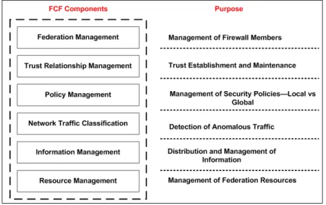
units that belong to the federation. The collaborating firewalls can then update their rule bases and policies to incorporate this new information. Figure 1 shows the 6 functional components of the FCF.
Figure 1: The FCF Functional Components
Federation Management: The purpose of federation management is to control member-ship of new firewall elements to the federation. This layer is responsible for establishing an initial trust between the firewall and the federation. If membership is not carefully con-trolled, denial of service attacks would be easy to orchestrate. For example, a rogue firewall could join the federation and inject falsified policies into the system. This could be used to deny service to members of the federation and their respective networks. Further, it could be used to allow unauthorized access to federation networks.
Trust Relationship Management: The Trust Relationship Management (TRM) com-ponent is used to maintain the member relationships once firewall elements have joined the federation. TRM addresses issues such as information authentication and credential management. Information authentication is needed to prevent denial of service. Credential management is needed because of the possibility that members could become rogue after being allowed to join the federation.
Policy Management: The policy management component is responsible for the manage-ment of local and global firewall security policies.
Network Traffic Classification: The network traffic classification component governs the types of systems needed for the detection of network anomalies.
Information Management: The information management component addresses an array of issues. It governs the way in which information is transported throughout the federation, and it is responsible for addressing the issues of data caching and staleness. In certain cases, the policies that are distributed will be long-term policies, and staleness will not be of concern. However, because of the dynamic nature of networks and attacks, there will be other policies that will not be needed for long periods of time. This will be the case if IP addresses are used as part of the security policy. For example, a particular host might be classified as malicious at some point in time. Later, a system administrator could quar-antine the host and clean the system. After the system has been cleansed, it should be able to participate in network activities again. Therefore, the original security policy would now be deemed unnecessary and will need to be removed from the collaborating firewalls. Lastly, this component addresses the issue of information confidentiality and integrity. This is accomplished with encryption mechanisms, and this component governs the types of en-cryption techniques that are used throughout the federation.
Resource Management: In order to provide scalability, resources within the federation need to be managed. The resource management component administers the mechanisms needed for robustness and scalability.
3.2.1 Experimental Evaluation of the FCF
For the purpose of evaluating the concepts underlying the FCF, an experimental evaluation was performed. Three firewall units were built using laboratory PCs running the Fedora Core 4 Linux operating system. The firewall functionality was implemented with the ipt-ables software package. The classification mechanism used for this experiment was the PortSentry software package. PortSentry is a program that can detect network scanning. Once a scan is detected, it can be configured to automatically update the firewall rules in iptables. The nmap software package was used to scan the hosts in the experimental network. For the purposes of this experiment, the network scan was used to simulate real
network attacks. Finally, the netcat software package was used as the transport mechanism. In order to test the system, nmap was used to scan the nodes in the experimental network. As the nodes were scanned, PortSentry would detect the scan and modify the iptables of the scanned host. A Perl script that was invoked every 60 seconds would examine the current state of the firewall rules and compare it to the previous state, which was stored in a file. If the firewall rules had changed, this indicated that PortSentry had detected a scan. If the firewall rules had changed, the data was written to a file to be used as a comparison when the script was called at the next 60 second interval. This new information was then distributed to the other nodes of the federation by using a client-server system built with the netcat software. The goal of the experiment was to evaluate the properties of the framework. The following questions were answered with the experimental evaluation:
1. Can the FCF stop malicious activity if the source has to pass through a collaborating firewall? Yes
2. Can the FCF enable networks to be preemptively protected because of the propagation of classification information (i.e. if one of the collaborating firewalls detects an attack and distributes the information to the federation before the attacker targets the other networks)? Yes
3. Is denial of service possible in the FCF because of IP spoofing? Yes
4. Is denial of service possible if a rogue firewall joins the federation? Yes
5. Can unauthorized access be granted to a network protected by a collaborating firewall if a rogue firewall joins the federation and injects fraudulent information into the system? Yes
The experimental results show that the FCF concept is valid and has great potential for implementing a reliable, distributed Internet security model.
3.3 The Distributed Firewall and Active Response Architecture
The development of the FCF allowed us to refine the architecture needed for implementing distributed Internet security. Our work with the FCF concepts allowed us to evolve the
architecture into its current state of design. This section describes the current specifications of our proposed distributed firewall and active response architecture.
3.3.1 High-level Architectural Description
The architecture was designed based on the concept of hosts within a trusted domain of administration that can detect anomalous behavior and create firewall blocking policies against the anomalous host. These blocking policies are shared with the neighborhood members of the domain of administration. Once a policy is created by a host or received from a neighbor, the policy is translated into a firewall rule that denies access to or from the anomalous host. The fundamental design principle of this architecture is the following: Once a source IP address has been classified with an anomaly detection mechanism as being untrustworthy, deny all access to or from the anomalous host for all members of the trusted domain of administration. We define the anomaly detection mechanism as any tool that can be used to detect abnormal computer or network activity. Being classified as untrustworthy implies that the source of an attack has malicious intentions and can issue other harmful exploits against the hosts within the Trusted Domain of Administration (TDA). The TDA is defined as the set Σ ={S1, S2,· · ·, SM}of hosts under the control of a single administrative
authority.
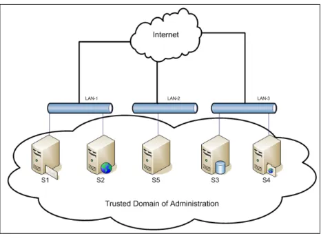
Figure 2 will be used to illustrate a discussion of the architecture. From Figure 2, the TDA is composed of Σ ={S1, S2, S3, S4, S5}, where each Si is some type of host possibly
offering network services to the Internet. Further, we assume that each host uses a host-based firewall such as the UNIX host-based iptables and some type of attack detection software. As seen in Figure 2, the TDA can span across multiple Local Area Networks (LAN). The only requirement is that the hosts are administered by a single administrative authority. There is a purpose for the definition of the TDA. Trust is a critical aspect of this architecture. If trust is neglected, there is a possibility that false policies can be injected into the system such that denial of service could be issued against random hosts. Therefore, a well defined TDA is required. Using the definition of the TDA as given above, trust can be achieved. Since a host must trust its administrator (by default), and each host in the TDA trusts the
Figure 2: A Trusted Domain of Administration
same administrator, then each host in the TDA can trust one another as a consequence of transitive trust.
A simple description of the behavior of this distributed firewall and active response architecture follows. Each Si has a detection process that is monitoring for attacks. Once
an attack is detected, the offending IP source address is added to a security policy database and a filtering rule is created within its local host-based firewall that denies all access to or from the offending IP address. Then, the host sends this information to each of its neighbors within the TDA so that they can also add a deny rule for the offending address. This process is an act of distributed active response that implements preemptive protection. Consider the case where a malicious node issues a Secure Shell (SSH) dictionary attack against S1. OnceS1has detected the attack, a blocking rule will be created for the offending IP address, and after distribution the other neighbors will have a blocking rule too. At some time in the near future, the same malicious node issues a sequence of attacks againstS5. But, because S5 has previously added a blocking rule based on the distributed security policy received fromS1, it will not be affected by the attacks. Hence,S5 has been preemptively protected.
3.3.2 Detailed Architectural Description
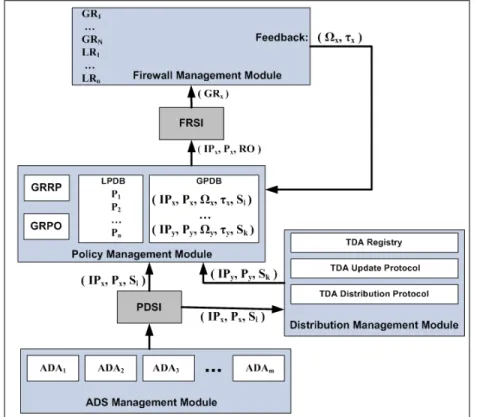
Figure 3 shows a block diagram of our distributed firewall and active response architecture. The architecture is composed of 4 primary management modules: Firewall Management,
Figure 3: The Distributed Firewall and Active Response Architecture
Policy Management,Distribution Management, and Autonomous Detection System (ADS) Management. Further, the architecture contains 2 specification interfaces: Firewall Rule Specification Interface and Policy Description Specification Interface. This system is de-signed to be completely distributed with no centralized control. Each member of the TDA must run a system implementation that conforms to the architecture’s design specifications. However, the implementation is system independent and can be developed with whatever technology the developer chooses.
3.3.2.1 Autonomous Detection System Management Module (ADSMM)
The ADSMM is simply the collection of independent Autonomous Detection Agents (ADA) that are active on the local system and the collection of rules that define how the ADA must interact with the policy management module. An ADA is an autonomous system
that can detect computer and network attacks. The ADA can be as simple as a process monitoring the local host for failed login attempts to a full scale IDS deployment such as the SNORT IDS. The ADS was designed to be highly modular and extensible so that researchers can easily investigate new attack detection theories and test the active response of their designs. Further, the modularity allows for many different types of independent, target-specific, autonomous attack detectors to reside on a single host thereby providing a more robust defense in depth strategy for the local host and the overall TDA. Currently, the architecture specifies one rule for the ADS: the ADA must be implemented such that its output adheres to the contract offered by the PDSI.
3.3.2.2 Policy Description Specification Interface (PDSI)
The PDSI is an interface that offers a globally recognized policy description that all members of the TDA interpret with the same meaning, i.e. it is a formal syntax describing a policy (a policy language). The following is the PDSI contract: ( IPx, Px, Si ). The syntax is
a 3-tuple containing the IP address of the attacking host (IPx), the policy action to take
against the attacking host (Px), and the host identifier (Si). The host identifier is some value
that uniquely identifies the host that generated the Policy Description Specification (PDS). Px is a policy action construct. The architecture currently defines only one action: Px =
DENY. Future extensions can be made whereby one might offer rate-limiting or redirection definitions. However, Px shall never be extended to offer an operation that elevates a
security privilege, i.e. Px = ALLOW. The ADA issues the PDS to the policy management
module and the distribution management module via the PDSI.
3.3.2.3 Policy Management Module (PMM)
The PMM contains 4 components: Local Policy Database (LPDB),Global Policy Database (GPDB), Global Rule Removal Protocol (GRRP), and Global Rule Placement Optimizer (GRPO). The LPDB is the collection of security policies that have been defined by the system administrator for the local host. For example, if the local host is a web server, the list of local policies could be stated as the following: {allow from any to localhost service http; deny from any to localhost service any}. The policy states that the local host can
receive inbound Hyper Text Transport Protocol (HTTP) connections and all others are to be denied. The GPDB is the collection of 5-tuples having the following form: (IPx,Px, Ωx,
τx, Si ). This list of variables represents the IP address of the anomalous host, the policy
action to apply against the anomalous host, the firewall hit-count (Ωx), the firewall hit-time
(τx), and the host identifier. The firewall hit-count and hit-time are feedback variables that
are received from the local host’s firewall module and are used by the GRRP and GRPO. The architecture defines that the hit-count is initialized to a value of 1 and the hit-time is set to the local host’s current system time upon insertion into the GPDB. These values are recalculated over time by the firewall management module. The GRRP and GRPO are responsible for removal of global firewall rules and optimization of their placement within the firewall rule base, respectively. These components will be described in more detail in Section 3.3.4. Once new policies are received by the PMM, they are inserted into the GPDB. After insertion into the GPDB, the policy is sent to the firewall rule specification interface for insertion into the firewall rule base.
3.3.2.4 Firewall Rule Specification Interface (FRSI)
The FRSI offers a contract between the firewall management module and the PMM, and the PMM must be implemented such that it conforms to the contract. The FRSI contract has the following form: ( IPx, Px, RO ). The 3-tuple contract contains the IP address of
the anomalous host, the policy action to apply against the anomalous host, and the Rule Operation (RO). Three types of rule operations have been defined: {RO = Insert, RO = Delete, RO = Modify}. These operations define the firewall functions of inserting a new rule, deleting an existing rule, or modifying an existing rule. The FRSI is responsible for dynamically mapping the data contained within a received contract into a firewall rule that conforms to the firewall’s native syntax. Using an interface such as this offers extensibility because the architecture will not be constrained to one type of firewall product. The FRSI can be modified by the system implementer to map the data to the syntax of the desired firewall that will be used.
3.3.2.5 Firewall Management Module (FMM)
The FMM is responsible for dynamically configuring the firewall rule base when rule struc-tures are received from the FRSI. Further, the FMM collects the hit-count and hit-time feedback variables and sends these variables to the PMM. The hit-count represents the number of times that a rule within the set of global rules has been matched (hit) by a particular incoming IP address and the hit-time represents the local system time of the last hit.
3.3.2.6 Distribution Management Module (DMM)
The DMM receives the 3-tuple ( IPx, Px, Si ) either from the local host or from one of
the local host’s neighbors within the TDA. If the tuple is received from the local host, it is immediately distributed to the other members of the TDA. And, if it is received from one of its neighbors, it is immediately sent to the PMM for processing. The DMM contains three components: TDA Registry, TDA Update Protocol, and TDA Distribution Protocol. The TDA registry stores host identifier information. At minimum, this is a list of all the members of the TDA. The identifier values are not yet strictly defined by the architecture. However, the suggested values areSi ={IPi,Host N amei,P ublic Keyi }, which is a set containing
a member’s IP address, an assigned host name, and its public encryption key. The TDA update protocol defines policy update procedures. The architecture currently defines one procedure, which is to update the GPDB and firewall rule base immediately upon receiving new policies. However, future implementations can define procedures for periodic update intervals of the GPDB whereby the host can send copies of its local GPDB to other members of the TDA. Then, a TDA member can contain its GPDB and a copy of other members’ GPDBs. The copies represent a global view of attack activity and can be used by the GRRP and GRPO for making more intelligent removal and optimization decisions. Finally, the TDA distribution protocol defines how the TDA members will distribute information between each other. This protocol is in development and is not yet defined.
3.3.3 Complexities of the Architecture
There are some architectural complexities that need to be addressed: The possibility of a large number of firewall rules, Dynamic Host Configuration Protocol (DHCP), and Network Address Translation (NAT). As seen from the FMM in Figure 3, there are a total of n + N firewall rules configured within a local host’s firewall. The n LPDB policies map to the n local firewall rules (LR), and the N GPDB policies map to the N global rules (GR). Each member of the TDA will contribute some proportion of the total number of policies within the GPDB and the total number of global rules in the firewall rule base. As the number of TDA members increases, the value of N will increase as new attacks are observed. Normally, n will be a modest value that remains approximately constant for a host based firewall. So, as N increases it becomes the dominating factor of n + N. Each incoming packet into the host must be processed by the firewall. Most firewall implementations will start at the top of the filtering rule list and process down the list until a match is found. Once a match is found, the firewall makes an access control decision based on the matched rule’s definition. Meanwhile, other packets into the host must wait in a connection queue until it is their turn to be processed by the firewall. The amount of time needed by the firewall to process a packet can be considered as a queuing service time ST. The service time is probabilistic
in nature. However, in certain cases, as the number N of global rules increases, ST can
be approximated as being proportional to N. Therefore, there is a possible degradation of network performance for the host as the number of global firewall rules increases. This is most significant if the host is an Internet server because of the amount of packets that must be processed by the server’s firewall. The case where the above assumption holds is for a host with a small probability that a packet belonging to a particular network connection C is abnormal, i.e. a host that is not attacked very often. Mathematically, this assumption is stated as follows: P r(C = anomalous) ≈ 0. For this particular case, as N increases, the average service time for a packet being processed by the firewall can be modeled by Equation 1.
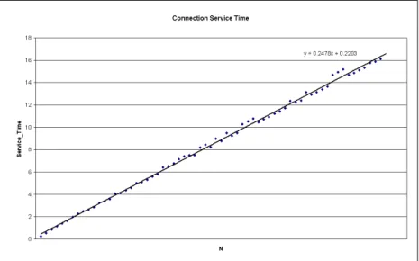
In Equation 1, δ is the amount of time needed for a packet to be processed by the firewall without any rules. Figure 4 shows a plot of the firewall service time as a function of N for a host running the Redhat Linux operating system and using an iptables firewall. The data
Figure 4: Experimental Results of Firewall Service Time as a Function of N
shown in Figure 4 represent the service time for a packet passing through a firewall having a number rules from N = 0 to N = 65535. The best fit line equation isST = 0.2478*N +
0.2203, and the service time is in units of milliseconds.
DHCP is a protocol that is used to dynamically configure a host’s networking parameters at bootstrap time. When the host boots, it queries a DHCP server and requests its network parameters, one of which is its IP address. A DHCP server assigns a lease time for the IP address that it offers to a client. Once a host has obtained an IP address from the DHCP server, it must renew the IP address when the lease time expires. Upon renewing its IP address, the host may or may not receive the same IP address that it received previously. Many Internet Service Providers (ISP) use DHCP for managing their IP address ranges. The possibility that a host will not receive the same IP address when its lease time has expired causes problems with the proposed architecture. Consider the case where a host within some ISP’s address range is classified as being anomalous by a TDA member. This offending host will be blocked by the members of the TDA. But, at some time in the future, the host’s lease time expires, and it retrieves a different IP address. The host’s original
IP address will eventually be assigned to another customer of the ISP. At this point, the TDA will be blocking access to an IP address that now belongs to another host that did not attack the TDA. Hence, the TDA is causing denial of service to the current owner of the IP address.
NAT is technology implemented in network routing devices that maps internal IP ad-dresses to external IP adad-dresses. NAT can be configured to do one-to-one mapping or many-to-one mapping. With one-to-one mapping, the routing device maps a host’s internal IP address to a constant external IP address. The one-to-one NAT mapping does not im-pose limitations to this architecture. However, with the many-to-one mapping scheme, the routing device will map many internal IP addresses to a single external IP address. The many-to-one mapping can cause issues with the architecture. Consider the case where some host within a many-to-one NAT based network is detected as being anomalous. When the system applies a blocking rule to the anomalous IP address, the system will be blocking access to all hosts within the NAT based network.
3.3.4 Solutions for the Complexities
The GRPO and GRRP components of the PMM were designed to solve these architectural complexities. The GRPO component is designed to optimize the placement of the global rules within the firewall rule base for the purpose of reducing the packet waiting time during an attack. This optimization technique alleviates the issue of large numbers of global rules. The global rules are of the following form: {deny from IPx to localhost service any}. All
of the global rules in the firewall must be processed first. Then, the local policy rules must be processed. This is a consequence of the logical ordering of rules required in an access control list. An example will be given to illustrate. Consider the following firewall rule list:
{
deny from 1.2.3.4 to localhost service any; allow from any to localhost service http; allow from any to localhost service ssh;
deny from any to localhost service any; }
This sequence of rules states that IP address 1.2.3.4 should not be given access to any ser-vices on the localhost. But, all other IP addresses are allowed access to HTTP and SSH. The last rule is the default rule that is used to deny access to any other service on the local host. The first rule represents a global rule, and the others represent local rules. If the first rule is placed after the second rule, then 1.2.3.4 would be able to access HTTP. However, that defeats the goals of this architecture, which is to deny access to any service on the local host once a host has been classified as anomalous. Hence, all of the global rules generated by an ADA or received from another TDA member must be processed before the local policy rules. The idea behind the GRPO is the following. The anomalous IP ad-dresses are monitored by the FMM, and the “heavy-hitters” (the anomalous IP adad-dresses) that are currently attacking the host have their global rules placed at or near the top of the global rule list. For this to be achieved, the hit-count and hit-time feedback variables are used to make intelligent placement decisions. The FMM sends the hit-count and hit-time variables to the GPDB once a match is made in the firewall rule base for the anomalous IP addresses. The GRPO component uses the following algorithm to optimally order the rules in the global rule list.
Algorithm GRPO X={GP DB.(IPi,Ωi, τi)}; ∆τi=τc−τi; Z ={X : ∆τi < T0}; Y =X−Z; maxsort(Z, Ωi); minsort(Y, ∆τi); X←Z||Y; UpdateRules( X.IPi);
End Algorithm GRPO
The set X is extracted from the GPDB and all of the tuples satisfying ∆τi < T0 are
extracted from X and stored in the set Z. The temporal optimization parameter,T0, defines a threshold value for the time range calculated in ∆τi. ∆τi is defined as the time difference
between the current system time, τc, and the last time, τi, that the anomalous host IPi
has attempted to make a connection with the local host. This implies that Z contains the 3-tuples for some set of anomalous IP addresses that have attempted to connect within the lastT0 seconds. Y contains the remainder of 3-tuples for the anomalous IP addresses that have not attempted a connection recently, where recently is defined by T0. The maxsort() function takes the list of 3-tuples and sorts them using Ωi as the sorting key. This list
is sorted from maximum Ωi to minimum Ωi. The minsort() function takes the list of
3-tuples and sorts them using ∆τi as the sorting key. This list is sorted from minimum
∆τi to maximum ∆τi. Then, X is replaced with the concatenation of Z and Y. Finally,
the UpdateRules() function updates the logical arrangement of global rules in the firewall based on the updated ordering of IP addresses stored in X. The overall result is that the most recent anomalous hitters are sorted in such a way that the ones that are currently attacking the most are near the top of the list. This reduces the queue waiting time for normal packets because the anomalous packets of a currently attacking host are processed quicker.
The GRRP is designed to remove global rules that have become stale, possibly as a result of DHCP. The architecture needs to remove rules for hosts that have not attacked the host recently. Removing stale rules will alleviate the issues with large numbers of rules and DHCP. GRRP is designed to remove global rules based on the 2 variables, Ωx and
∆τx = τc−τx, associated with an IP address, IPx. If it has been a long time since IPx
has attacked the host, then ∆τx 0 and we want to consider removing the global rule for
IPx. However, we want to also consider how often IPx was attacking the server, and this
information is contained in Ωx. We define the rule removal optimization parameter,ωx, as
the following:
ωx =
∆τx
Ωx
(2)
Equation 2 allows ωx to be normalized relative to the hit-count for a particular IPx. By
definition, Ωx ≥1. Hence, ωx will be bounded byωx = ∆τx and ωx = 0, for all ∆τx ≥0.
We define the rule removal timing threshold, TR, as a time interval such that if ωx > TR
Algorithm GRRP ∀x∈X
If (ωx> TR)
Then Remove(GPDB[x], FR[x]); End Algorithm GRRP
In this algorithm, X is the set of all IP addresses associated with the GPDB and the firewall rule base. The instance x can be used to index into both the GPDB and the firewall rule base. Observing the dynamics of Equation 2, one can see that if host x issues many attacks against a host (implying that Ωx1), then the rule will remain in the GPDB and
firewall rule base for larger amounts of time because ∆τx will need to grow larger in order
to satisfyωx> TR. Therefore, the policies and rules will remain active longer for hosts that
are more active with their attacks.
3.3.5 Case Study–Using the Distributed Firewall and Active Response Archi-tecture to Prevent the SSH Dictionary Attack.
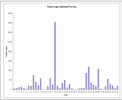
There is an attack class known as the SSH dictionary attack that is in wide spread use by attackers. An SSH dictionary attack is an attempt to exploit a user authentication system by systematically guessing username and password pairs. Figure 5 shows dictionary attack results for an SSH server connected to the Internet. The data in Figure 5 represent the total number of dictionary attack attempts per day for 44 consecutive days for a Georgia Tech Savannah campus email server. Figure 6 displays the total number of unique IP addresses associated with these failed login attempts. There was an average of 324.3 dictionary attacks per day, an average of 3.2 unique IP addresses issuing the attacks per day, and an average of 81.8 dictionary attacks per IP address per day. The data included a maximum of 3533 dictionary attacks on day number 18.
Several solutions exist [30] for detecting and responding to the SSH dictionary attack for a local host. The operation of an SSH dictionary attack detection agent is as follows. Failed login attempts are monitored by the agent. Each IP address associated with a failed login is recorded along with an associated counter. A counter threshold and a time range threshold are defined such that if the failed login counter increases beyond the counter
Figure 5: SSH Dictionary Attacks Against an Internet Server
threshold during a time range that is less than or equal to the time range threshold, then the IP address is assumed to be an attacker that is performing an SSH dictionary attack. When the detection agent observes an attack, it generates a firewall blocking rule within the local firewall against the attacking host. However, the SSH dictionary attack detection solutions that are currently available work in an independent fashion. Using the proposed architecture, the detection agent would operate within the ADS management module on one or more or possibly all of the TDA members . Once an attack is observed, the architecture provides the mechanisms needed for dissemination of the attack information by way of distributed security policy.
A simulation program was written so that the preemptive protection provided by the proposed distributed firewall and active response architecture could be analyzed for an SSH dictionary attack scenario. The simulation was based on a TDA of 5 members, S1-S5. There was a single host attacking the servers using 4 types of SSH dictionary attack methods: Normal,Random, Weighted, andRound Robin. The normal method is based on the common type of SSH dictionary attack. The attacker issues many login attempts against a single server before targeting another server. The random method models an attack where the attacker issues single login attempts against the servers in a random order. The weighted method models an attack where the attacker focuses on a primary server but occasionally issues an attack on another server randomly during the process. Finally, the round robin method assumes a model whereby the attacker issues one login attempt per server in a round robin fashion.
The simulation results are shown in Table 1. The first four rows of data reveal the
Table 1: Simulation Results of Preemptive Active Response Attack Method S1 S2 S3 S4 S5
Normal 0 0 10 0 0
Random 7 8 8 10 4
Weighted 10 1 4 2 0
Round Robin 9 10 9 9 9
number of failed login attempts on each server before being blocked with the distributed active response system. The fifth row presents the results for a non-distributed active response system. A threshold value of 10 was used in the SSH dictionary attack detection system. The threshold value is the number of failed login attempts from a single source IP address that is needed before a blocking rule is applied, i.e. we assume that 10 consecutive failed login attempts is due to an SSH dictionary attack. The data show that the architecture performs well for the normal dictionary attack method. The random and weighted methods perform marginally well. But, the round robin method is only slightly better than the non-distributed active response method. In the non-distributed active response case, each server will have 10 login attempts before creating its local blocking rule against the attacking host. The simulation results show that the architecture can achieve very good preemptive protection during the event of a normal dictionary attack.
3.3.6 Summary
The preliminary research includes an extensive study of intrusion detection systems and dis-tributed firewalls, the application of artificial intelligence and machine learning algorithms for the purpose of observing intrusive behavior and computer attacks, the development of a “first generation” distributed firewall system (the FCF) that allows dynamic firewall rule creation and active attack response, experimental evaluation of the first generation dis-tributed firewall system, and the development of a “second generation” disdis-tributed firewall and active response architecture. The design of the current distributed firewall and active response architecture was driven by observations and conclusions that were made during the evaluation and analysis of the first generation system. The work remaining for this research includes the development of a testbed prototype that implements the current ar-chitecture, an in-depth architectural analysis of the current arar-chitecture, and an extensive analysis of various performance metrics that have been defined for guiding the design of the TDA distribution protocol and various firewall optimization techniques.
CHAPTER IV
PUBLICATIONS
4.1 Conference Papers
• Lane Thames, Randal Abler, Ashraf Saad: Hybrid Intelligent Systems for Net-work Security, Proceedings of the ACM Southeast Conference 2006.
• Lane Thames, Randal Abler: Implementing Distributed Internet Security Us-ing a Firewall Collaboration Framework, Proceedings of the IEEE Southeast Conference 2007.
• Lane Thames, Randal Abler, David Keeling: A Distributed Active Response Architecture for Preventing SSH Dictionary Attacks, Proceedings of the IEEE Southeast Conference 2008.
• Lane Thames, Randal Abler, David Keeling: A Distributed Firewall and Active Response Architecture Providing Preemptive Protection, Proceedings of the ACM Southeast Conference 2008.
4.2 Conference Papers in Review
• Lane Thames, Randal Abler: Mentoring Undergraduate Students Preparing for Graduate Study in Engineering–A CREATE Case Study, Frontiers In Education (FIE) 2008, Abstract Accepted, Paper in Review.