TECHNICAL UNIVERSITY OF CLUJ-NAPOCA
ACTA TECHNICA NAPOCENSIS
Series: Applied Mathematics, Mechanics, and Engineering Nr. 62, Vol. III, September, 2019
THEORETICAL CONSIDERATIONS REGARDING THE DYNAMIC
ABSORBER
Monica BĂLCĂU, Aurora-Felicia CRISTEA
Abstract: The paper is a theoretical one that focuses on the influence of dynamic absorbers in the reduction and elimination of torsion vibrations. The dynamic absorber is used for the reduction of the amplitude of the torsion vibrations of crankshafts. According to the construction restrictions, we notice that the dynamic absorber does not increase the number of resonance phenomena, irrespective of the order of the harmonic that causes forced vibrations.
Key words: dynamic absorber, torsion vibrations, reduced masses.
1. INTRODUCTION
The dynamic absorber is an oscillation system that is attached to a system with the purpose of reducing its vibrations. The crankshaft of a piston-based engine, together with its gearings, forms an oscillating system. The oscillation amplitudes can become very dangerous when they resonate with the device, which is when the rotation of the shaft becomes the same with one of its critical rotations.
By adding a dynamic absorber to a device, the primary system’s degrees of freedom increase by a unit and thus the resonance curve is modified. If the parameters of the dynamic absorber are properly chosen, the resonance curve of the system composed of primary system and absorber has a minimum declared value in a frequency area in which the primary system has only one maximum. Thus, there is a significant damping in the primary system vibrations in the vicinity of its resonance.
The dynamic absorber can be designed at the same time with the structure whose vibrations must be eliminated or can be added later on. Also, it can act upon the entire structure or can be attached to the element whose functioning produces vibrations in the overall structure.
The dynamic absorber is also used to reduce the amplitude of the torsion vibrations in the case of crankshafts. In order to calculate the torsion vibrations of such a complex elastic system, this system has to be turned beforehand into a simpler equivalent dynamic system, formed of an elastic linear shaft of negligible mass loaded with circular reduced masses obtained by the reduction of the mobile gears.
This paper is a theoretical one that presents the study of mechanical systems of five reduced masses that receive a dynamic absorber placed at the and of the mechanical system. The harmonic x acts upon the mechanic system is
applied to the reduced mass m1, m2, m3, m4 and
mv.
The mass that receives the dynamic absorber is acted upon with an order x harmonica which results by the decomposition of the Fourier series of the disruptive force with a periodical variation acting upon this mass.
2.THE MECHANICAL SYSTEM FORMED OF FIVE REDUCED MASSES, THE DYNAMIC ABSORBER PLACED AT THE AND OF THE SYSTEM
noted m1, m2, m3, m4, mv (Fig.1.), which are
connected through the reduced crankshaft and
presenting the elastic constantsm c43, c32, c21,
c1v, dynamic absorber is attachend to the last
reduced mass mv and the only harmonic x acts
upon the mechanic system applying on the
reduced mass m2 .
Fig.1 Mechanical system
Next we replace the dynamic absorber with an equivalent system formed of the reduced
mass m5 and the elastic shaft of a negligible
mass with the elastic constant cv5 (Fig.2).
Fig.2 Equivalent mechanical system
We write the differential equations that guvern the vibratory torsion movements that the five reduced masses mechanical system with mechanical scheme presented in figure 2 [1-6]:
(1)
(
a a)
P cos( t 2π ε) cdt a d
m 24 43 4 3 x
2
4 + − = Ωx + −
(
)
(
)
(
a a)
0 cdt a d m
0 a a c a a c dt
a d m
v 5 v5 2
5 2
5
5 v v5 1 v 1v 2
v 2
v
= − +
= − +
− +
The expressions for the elongations ai
(i=1~5) for the torsion vibrations executed by
the six reduced masses measured on the reduction circle with a radius r, are the followings:
a1 = A1 cos (Ωxt-ε)
a2 = -A2 cos (Ωxt -ε)
a3 = -A3 cos (Ωxt -ε)
a4 = A4 cos (Ωxt-ε)
av = Av cos (Ωxt-ε)
a5 = A5 cos (Ωxt-ε) (2)
The elastic constants of the segments of crankshafts between the two consecutive reduced masses and the mechanical axial moments of the reduced masses in relation to the symmetrical geometry axis of the shaft must be chosen so that the kinetic energy and the potential energy of the real vibrant system (formed by the crankshaft and its mobile gears) is equal to the kinetic energy and the potential energy of the reduced vibrant system.
In order for the mechanical system formed
from the mass m5 and the part of the shaft with
the elastic constant cv5 to be dynamically
equivalent with the dynamic absorber attached
to the reduced mass mv and thus to be able to
apply the same torque as the dynamic absorber it is necessary and sufficient to:
(
)
22
5
r l L m
(
2)
20 2v5
l L r
l L m
c = + ω (3)
In addition, the harmonic x pulsation is expressed with
Ωx = x⋅ω0 (4)
where X represents the order of the harmonic, that is the number of oscillations that the
harmonic executes in a time T0, in which the
shaft executes a complete rotation of 2π rad,
and ω0 is angular constant speed of rotation for
the reduced crankshaft.
The amplitudes of the torsion vibrations
executed by the five reduced masses Ai (i=1~5)
are provided by the expressions:
Δ Δ
Ai= i (i=1~5) (5)
The dynamic absorber is dimensioned in such a say that
2
x
l
L
=
(6)3. MATHEMATIC MODELATION
The mechanical system was established in such a way starting from the following hypotheses:
-the angular speed is constant, in reality the
angular speed varies;
-one masse situated on the flywheel is
assimilated for a dynamic absorber ;
-the mathematic modelation takes into account
the system formed of the crankshaft and its mobile gearings (pistons, segments, vaults, rods, roller bearing), flywheel.
The corresponding mechanical system is the
one composed of five reduced masses mv, m1,
m2, m3, m4, mv which receives a dynamc
absorber represented in figure 2. Mass m1 is
considered reduced mass associated with the
first cylinder, the mass m2 is the reduced mass
corresponding cylinder 2, m3 is the reduced
mass corresponding cylinder 3, m4 is the
reduced mass corresponding cylinder 4, mv is
the reduced mass corresponding flywheel and
m5 is the reduced mass corresponding dynamic
absorber (Fig.2).
Taking into account the mechanical system from chapter two of this paper, we can solve the differential equation system (1) using MathCad. This offers values for displacement, velocity and acceleration.
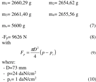
Mathematical modeling was done for the next parameters:
- n= 1650 rot/min
- the reduced masses corresponding to the crankshaft with the mobile crews and the flywheel are:
m1= 2660,29 g m2= 2654,62 g
m3= 2661,40 g m4= 2655,56 g
mv= 5600 g (7)
-Fp= 9626 N (8)
with
(
c)
p p p
D
F = −
4
2
π
(9)
where: - D=73 mm
- p=24 daN/cm2
- pc= 1 daN/cm2 (10)
The value of the reduced mass m5 calculated
with the relation (5) and specifying the following initial dimensions:
m=6,9 g L=85 mm
l=0,8 mm r=38,5 mm
result:
m5= 76,42 g
In figure 3, figure 4, figure 5, figure 6, figure 7 and figure 8 are represented displacement of
reduced masses m1, m2, m3, m4, mv and m5
within 1 second.
D
is
p
la
ce
m
en
t
[m
m
]
Time [s]
D
is
p
la
ce
m
en
t
[m
m
]
Time [s]
Fig. 4 Reduced mass m2 displacement
D
is
p
la
ce
m
en
t
[m
m
]
Time [s]
Fig. 5 Reduced mass m3 displacement
D
is
p
la
ce
m
en
t
[m
m
]
Time [s]
Fig. 6 Reduced mass m4 displacement
D
is
p
la
ce
m
en
t
[m
m
]
Time [s]
Fig. 7 Reduced mass m5 displacement
D
is
p
la
ce
m
en
t
[m
m
]
Time [s]
Fig. 8 Reduced mass mv displacement
It is observed that the largest displacement
are produced by reduced mass m2.
Next we represent the velocities
corresponding to the six reduced masses.
V
el
o
c
it
y
[
m
m
/s
]
Time [s]
Fig. 9 Reduced mass m1 velocity
V
el
o
c
it
y
[
m
m
/s
]
Time [s]
Fig. 10 Reduced mass m2 velocity
V
el
o
ci
ty
[
m
m
/s
]
Time [s]
Fig. 11 Reduced mass m3 velocity
V
el
o
ci
ty
[
m
m
/s
]
Time [s]
Fig. 12 Reduced mass m4 velocity
V
el
o
ci
ty
[
m
m
/s
]
Time [s]
Fig. 13 Reduced mass m5 velocity
V
el
o
ci
ty
[
m
m
/s
]
Time [s]
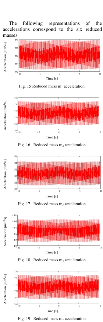
The following representations of the accelerations correspond to the six reduced masses.
A
cc
el
er
at
io
n
[
m
m
2/s
]
Time [s]
Fig. 15 Reduced mass m1 acceleration
A
cc
el
er
at
io
n
[
m
m
2/s
]
Time [s]
Fig. 16 Reduced mass m2 acceleration
A
cc
el
er
at
io
n
[
m
m
2/s
]
Time [s]
Fig. 17 Reduced mass m3 acceleration
A
cc
el
er
at
io
n
[
m
m
2/s
]
Time [s]
Fig. 18 Reduced mass m4 acceleration
A
cc
el
er
at
io
n
[
m
m
2/s
]
Time [s]
Fig. 19 Reduced mass mv acceleration
5. CONCLUSIONS
If the dynamic absorber is built such in relation (6) it does not introduce a new resonance phenomenon and the reduced masses that come from the reduction of the crankshaft and its gearings do not perform torsion vibrations.
From a practical point of view, it is not so easy to mount a dynamic absorber on the engine flywheel that could lead to the reduction of the torsion vibrations without misbalancing the engine.
Most of the time, the dynamic absorber is superior to any isolation system because it can be easily tuned so that it works in the range of the frequencies that need to be eliminated. Using a dynamic absorber is recommended In situations where the intrinsic frequency of the primary system is close to the frequency of the disruptive forces. This is the reason that the dynamic absorber can be used to reduce unbalanced forces which appear in the functioning of various machine parts.
6. REFERENCES
[1] Ripianu A., Crăciun I., Calculul dinamic şi de rezistenţă al arborilor drepţi şi cotiţi,
Editura Dacia, Cluj-Napoca, 1985, pag.122-126. [2] Ripianu A., Vibraţii mecanice, Atelierul de
multiplicare al Institutului Politehnic Cluj-Napoca,1977, pag.20-22.
[3] Bălcău, M., Ripianu, A., Case study of the mechanical system composed of four reduced masses that is subjected to a single harmonic X to wich we attached one dynamic absorber, over upon the another mass then the given two harmonic x, Acta Technica Napocensis, series Applied Mathematics and Mechanics, nr.51, vol.IV, ISSN 1221-5872, pp.99-106, 2008. [4] Bălcău, M., Arghir, M., The use of dynamical
absorbers, 13th International Conference ,,Automation in Production Planning and Manufacturing“, Zilina 2012, ISBN 978-80-89276-35-6, pag. 9-14.
[5] Bălcău, M., Opruţa, D., Pleşa, A., Bălcău, O.,
[6] Bălcău, M., Pleşa, A., Opruţa, D., Contributions to the study of diynamic absorber, particular case, lucrare prezentată în cadrul Conferinţei ERIN 2012 25-27 aprilie 2012 organizată de Czech Technical University in Prague, Faculty of Mechanical Engineering, publicată în Acta Polytechnica Scientific Journal în august 2012, CTU Publishing House, ISSN 1805-2363. [7] Todoruţ, A.; Cordoș, N. (2019). Evaluation of
the Vehicle Sideslip Angle According to Different Road Conditions. In: Burnete N., Varga B. (eds) Proceedings of the 4th International Congress of Automotive and Transport Engineering (AMMA 2018), pp. 814-819. AMMA2018 2018. Proceedings in Automotive Engineering. Springer, Cham, Copyright information © Springer Nature
Switzerland AG 2019, DOI:
https://doi.org/10.1007/978-3-319-94409-8_95, First Online: 30 September 2018, Print ISBN 978-3-319-94408-1, Series Print ISSN 2524-7778, Online ISBN 978-3-319-94409-8, Series
Online ISSN 2524-7786,
https://link.springer.com/chapter/10.1007/978-3-319-94409-8_95,
https://www.springer.com/us/book/97833199440 81.
[8] Cordoș, N.; Todoruţ, A. (2019). Influences of the Suspensions Characteristics on the Vehicle Stability. In: Burnete N., Varga B. (eds)
Proceedings of the 4th International Congress of Automotive and Transport Engineering (AMMA 2018), pp. 808-813. AMMA2018 2018. Proceedings in Automotive Engineering. Springer, Cham, Copyright information © Springer Nature Switzerland AG 2019, DOI: https://doi.org/10.1007/978-3-319-94409-8_94, First Online: 30 September 2018, Print ISBN 978-3-319-94408-1, Series Print ISSN 2524-7778, Online ISBN 978-3-319-94409-8, Series Online ISSN 2524-7786
[9] Iacob-Liviu SCURTU, Sanda Mariana BODEA, Ancuta Nadia JURCO, Design optimization method used in mechanical engineering. JIDEG, n. 11, p. 13-17, nov. 2016. ISSN 2344-4681. [10] L. Scurtu, L. Banfalvi, R. Curta, A. Steopan:
Using Vibrations in Smart Furniture Design, Acta Technica Napocensis-Series: Applied Mathematics, Mechanics, and Engineering, Vol.58, Issue 1, ISSN 1221-5872, Cluj-Napoca, 2015.
[11] Prodan Vasile Calin, Micle Valer, Rogozan Călin George, Szanto (Prodan) Maria – “Mathematical modeling of thermal desorption using linear regression analysis”, Environmental Engineering and Management Journal, “Gheorghe Asachi” Technical University of Iasi, Romania, ISI Journal, Factor de impact 1.435, February 2013, Vol.12, No. 2, pag. 365-369, http://omicron.ch.tuiasi.ro/EEMJ/
CONSIDERAȚII TEORETICE PRIVIND ABSORBITORUL DINAMIC
Rezumat: Lucrarea de faţă studiază efectul absorbitorului dinamic asupra vibraţilor de torsiune executate de sistemul mecanic compus din masele reduse m1, m2, m3, m4, mv supus acţiunii mai multor armonici de ordinul x. Se realizeză modelarea matemetica pornind de la ecuațiile diferențiale ce guvernează mișcarea vibratorie a sistemului mecanic propus. Sunt reprezentate grafic deplasările, vitezele și accelerațiile corespunzătoare maselor reduse.
De obicei absorbitorul dinamic este superior oricărui sistem de izolare, deoarece poat fii acordat cu uşurinţă, astfel încât să lucreze în zona frecvenţelor care trebuie eliminate. Utilizarea absorbitorului dinamic este recomandabilă când frecvenţa proprie a sistemului primar este apropiată de frecvenţa forţelor perturbatoare. absorbitorul dinamic nu majorează numărul fenomenelor de rezonanţă, oricare ar fi ordinul armonicei ce provoacă vibraţiile forţate.
Monica BĂLCĂU, PhD. Eng., Lecturer, Technical University of Cluj-Napoca, Faculty of Automotive, Mechatronics and Mechanical Engineering, Department of Automotive Engineering and Transports, Romania, [email protected], Office Phone 0264 401 610.
Aurora-Felicia CRISTEA, PhD. Eng., Associate Professor, Technical University of Cluj-Napoca,
Building of Machines Faculty, Mechanical Engineering System Department,