MICRO-CT EVALUATION OF THE MARGINAL FIT OF CAD/CAM ALL CERAMIC CROWNS
Christian Brenes
A thesis submitted to the faculty of the University of North Carolina at Chapel Hill in partial fulfillment of the requirements for the degree of Master of Science in the School of Dentistry
(Prosthodontics).
Chapel Hill 2014
Approved by:
ABSTRACT
Christian Brenes: CAD/CAM MATERIALS AND TECHNOLOGIES FOR ALL CERAMIC RESTORATIONS: A REVIEW OF THE LITERATURE
(Under the direction of Ibrahim Duqum)
Objectives: Evaluate the marginal fit of CAD/CAM all ceramic crowns made from lithium disilicate and zirconia using two different fabrication protocols (model and model-less). METHODS: Forty anterior all ceramic restorations (20 lithium disilicate, 20 zirconia) were fabricated using a CEREC Bluecam scanner. Two different fabrication methods were used: a full digital approach and a printed model. Completed crowns were cemented and marginal gap was evaluated using Micro-CT. Each specimen was analyzed in sagittal and trans-axial orientations, allowing a 360o evaluation of the vertical and horizontal fit. RESULTS: Vertical measurements in the lingual, distal and mesial views had and estimated marginal gap from 101.9 to 133.9 microns for E-max crowns and 126.4 to 165.4 microns for zirconia. No significant differences were found between model and model-less techniques. CONCLUSION: Lithium disilicate restorations exhibited a more accurate and consistent marginal adaptation when compared to zirconia crowns. No statistically significant differences were observed when comparing model or model-less approaches.
AKNOWLEDGEMENTS
First of all I want to thank Dr. Ibrahim Duqum for his support with this project; Dr. Lyndon Cooper for accepting me into the prosthodontic residency; Dr. Sompop Bencharit for his friendship and for sharing his knowledge with me during the residency.
TABLE OF CONTENTS
LIST OF TABLES ... vi
LIST OF FIGURES ... vii
LIST OF ABBREVIATIONS ... viii
CHAPTER 1: CAD/CAM MATERIALS AND SYSTEMS ... 1
INTRODUCTION ... 1
1. CAD/CAM MATERIALS ... 2
1.2 GLASS CERAMICS ... 2
1.3 ALUMINA BASED CERAMICS ... 3
1.4 LITHIUM DISILICATE ... 4
1.5 ZIRCONIA ... 6
2. CAD/CAM SYSTEMS ... 9
3. MARGINAL FIT ... 13
MATERIALS AND METHODS ... 19
RESULTS ... 23
DISCUSSION ... 27
CONCLUSION ... 33
LIST OF TABLES
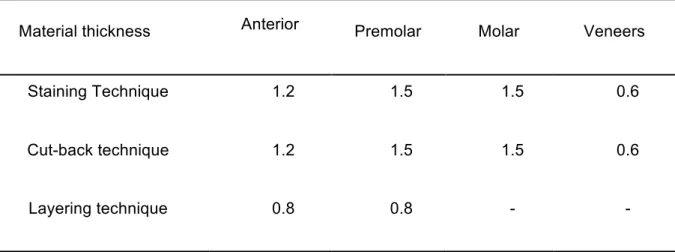
Table 1: Recommended dimensions for E-max CAD by Ivoclar Vivadent ... 5
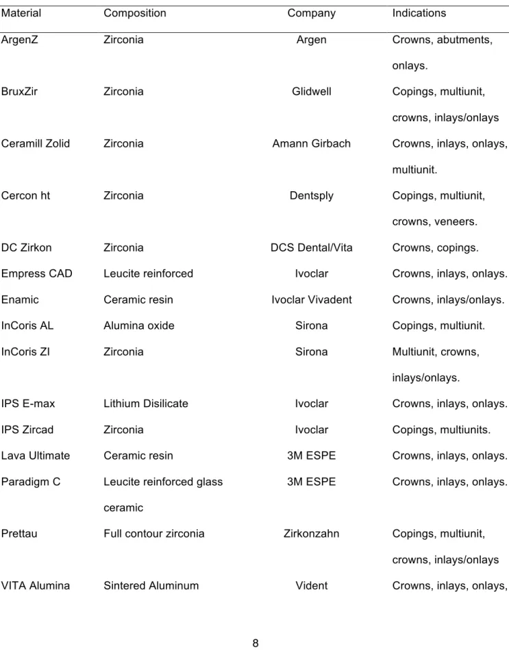
Table 2. Most used CAD/CAM materials for all ceramic restorations available for 2014. ... 8
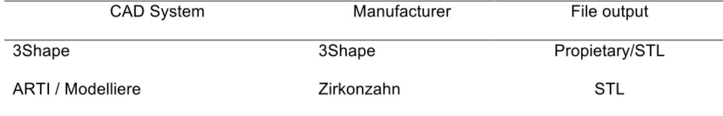
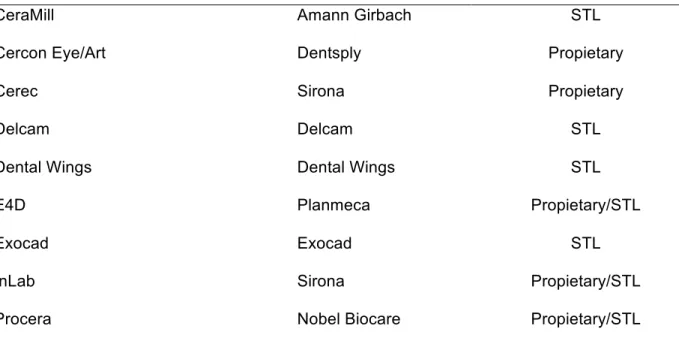
Table 3. Most used dental CAD systems available for 2014 ... 11
Table 4. Most used dental CAM systems available for 2014 ... 12
Table 5. Summary of research studies including marginal adaptation. ... 16
Table 6. Sample distribution between dental laboratories. ... 20
Table 7. Result of linear mixed models with compound symmetric covariance ... 23
Table 8. Least square means from the linear mixed models. ... 24
LIST OF FIGURES
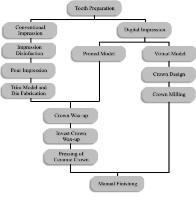
Figure 1. Digital and conventional workflow for all-ceramic crown fabrication. ... 34
Figure 2. Crown design using the In-Lab software (Sirona Dental) ... 35
Figure 3. Squematic representation of the 26 images selected for micro-CT analysis. ... 35
Figure 4. Micro computed tomography, sagittal image of crown at 100x magnification. ... 36
Figure 5. A) Schematic representation of the vertical misfit and B) Horizontal misfit. ... 36
Figure 6. Graphic representation of the specimen medians for E-max model group. ... 37
Figure 7. Graphic representation of the specimen medians for E-max model-less group. ... 37
Figure 8. Graphic representation of the specimen medians for zirconia model group. ... 38
LIST OF ABBREVIATIONS
CAD: Computer Aided Design
CAM: Computer Aided Manufacturing
FDP: Fixed Dental Prosthesis
OBJ: Object
SEM: Scanning Electronic Microscopy
STL: STEREO LITHOGRAPHY
Y-TZP: Yttria-Tetragonal Zirconia Polycrystal
CHAPTER 1: CAD/CAM MATERIALS AND SYSTEMS
INTRODUCTION
Dental crowns have been used for decades to restore compromised or heavily restored dentition, and for esthetic improvements. New CAD/CAM materials and systems have been developed and evolved in the last decade for fabrication of all-ceramic restorations.
Dental CAD/CAM technology is gaining popularity because of its benefits in terms of manufacturing time, material savings, standardization of the fabrication process, and
predictability of the restorations. When the CAD/CAM manufacturing process is employed, the number of steps required for the fabrication of a restoration is less compared to traditional methods (Fig 1). Another benefit of CAD/CAM dentistry include the use of contemporary materials and data acquisition instruments; which represents a non-destructive method of saving impressions, restorations and information that are saved on a computer and constitute an extraordinary communication tool for evaluation. Cooper (2011) stated that: “CAD/CAM technology is an efficient and effective point for critical evaluation of the proposed restorations prior to its fabrication”.
The incorporation of dental technology has not only brought a new range of manufacturing methods and material options but also some concerns about the processes involving
restorations fit, quality, accuracy, short and long-term prognosis (Miyazaki, 2009).
The purpose of this review is to provide an overview of the literature regarding the different materials and systems available until June 2014. In addition marginal fit of CAD/CAM
1. CAD/CAM MATERIALS
1.2 GLASS CERAMICS
The first in office ceramic material was Vitablock Mark I (Ivoclar Vivadent, Liechtenstein), it
was a feldspathic-based ceramic compressed into a block that was milled into a dental restoration (Poticny, 2012). After the invention of the Mark I block the next generation of materials for CAD/CAM milling fabrication of all-ceramic restorations were Vita Mark II (Ivoclar Vivadent, Liechtenstein) and Celay (VITA, Bad Säckingen, Germany), which replaced the original Mark I in 1987 for fine feldspathic porcelains primarily composed of silica oxide and aluminum oxide (Fasbinder, 2002) (Pallesen, et al. 2000). Mark II blocks are fabricated from feldspathic porcelain particles embedded in a glass matrix and used for single unit restorations available in polychromatic blanks nowadays. On the other hand, Celay ceramic inlays have been considered clinically acceptable by traditional criteria for marginal fit evaluation (Sorensen, et al. 1994).
Dicor-MGC was a glass ceramic material composed of 70% tetrasilicic fluormica crystals precipitated in a glass matrix; but this material is no longer available in the market (Chang, et al. 2003). Studies from Isenberg, et al. (1992) suggested that inlays of this type of ceramics were judged as clinically successful in a range from 3 to 5 years of clinical service (Kelly, et al. 1996). In 1997, Paradigma MZ100 blocks (3M ESPE, Center St. Paul, MN) were introduced as a highly filled ultrafine silica ceramic particles embedded in a resin matrix; the main advantage of this material is that it can be use as a milled dense composite that was free of polymerization shrinkage but can not be sintered or glazed (Poticny, et al. 2010).
In early 1998 IPS ProCAD (Ivoclar Vivadent, Liechtenstein) was introduced as a leucite reinforced ceramic similar to IPS Empress but with a finer particle size; this material was
Vivadent, Liechtenstein) and Paradigm C (3M ESPE, Center St. Paul, MN) that according to the manufacturer 3M ESPE it is a 30%-45% leucite reinforced glass ceramic with a fine particle size.
To overcome esthetic problems of most CAD/CAM blocks having a monochromatic
restoration; a different version was developed as a multicolored ceramic block which was called Vita TriLuxe (Ivoclar Vivadent, Liechtenstein) and also IPS Empress CAD Multiblock; the base of the block is a dark opaque layer, while the outer layer is more translucent; the CAD software allows the clinician to position or align the restoration into the block for the desired outcome of the restoration (Kurbad, et al. 2006) (Fritzsche. 2004).
In 2014 the Enamic (VITA, Bad Säckingen, Germany) material was released as a ceramic network infiltrated with a reinforcing polymer network that has the benefits of a ceramic and resin in one material but no clinical data is available (McLaren, et al. 2013).
1.3 ALUMINA BASED CERAMICS
VITA (Bad Säckingen, Germany) alumina blocks are In-Ceram Alumina is available for milling with the CEREC system (Sirona Dental, Charlotte, NC) and now compatible with other milling machines as well. Due to the opacity of alumina based ceramic materials the In-Ceram Spinell (VITA, Bad Säckingen, Germany) blocks were developed as an alternative for anterior esthetic restorations; it is a mixture of alumina and magnesia. Its flexural strength is less than
In-Ceram Alumina, but veneering with feldspathic porcelain for a more esthetic result could follow it after the milling process (Bindl, et al. 2004).
Nobel Biocare developed Procera material; for its fabrication high purity aluminum oxide is compacted into an enlarged die that is fabricated from the scanned data (Denissen, et al. 2000). The enlarged fabricated core shrinks to the dimensions of the working die when sintered at 1550o C; this material offers a very high strength core for all-ceramic restorations; the crown is
2001). More recently In-Coris AL (Sirona Dental, Charlotte, NC) has been introduced as a high strength aluminum oxide block with similar mechanical properties as Procera (Nobel Biocare, Zürich-Flughafen Switzerland).
1.4 LITHIUM DISILICATE
Lithium disilicate is composed of quartz, lithium dioxide, phosphor oxide, alumina, potassium oxide and other components. According to Saint-Jean (2014) the crystallization of lithium
disilicate is heterogenous and can be achieved through a two or three stage process depending if the glass ceramic is intended to be used as a mill block max CAD) or as a press ingot (E-max press).
Lithium disilicate blocks (blue blocks) are partially sintered and relatively soft; they are easier to mill and form to the desired restoration compared to fully sintered blocks; after this process the material is usually heated to 850°C for 20-30 minutes to precipitate the final phase. This sintering step is usually associated with a 0.2% shrinkage accounted for by the designing software (Shen, et al. 2014). Nowadays, blocks of lithium disilicate with the commercial name E-Max (Ivoclar Vivadent, Liechtenstein) are available for both in-office and in-laboratory fabrication of all-ceramic restorations; monolithic blocks require layering or staining to achieve good
esthetic results (Kelly, 2004). Different in vitro studies that evaluate marginal accuracy of milled lithium disilicate revealed that these restorations could be as accurate as 56-63 microns (May,
Russell, Razzoog, & Lang, 1998).
According to the manufacturer specifications the designing principles for E-max (lithium
Table 1: Recommended dimensions for E-max CAD by Ivoclar Vivadent
Material thickness Anterior Premolar Molar Veneers
Staining Technique 1.2 1.5 1.5 0.6
Cut-back technique 1.2 1.5 1.5 0.6
Layering technique 0.8 0.8 - -
Values are expressed in millimeters
During the crystallization process the ceramic is converted from a lithium metasilicate crystal phase to lithium disilicate. Some commercial types of ceramics are Empress CAD and IPS
E-max (Ivoclar Vivadent, Liechtenstein). The first one is a leucite based glass ceramic with a composition similar to Empress ceramic. IPS E-max was introduced in 2006 as a material with a
flexural strength of 360 to 400 MPa (two to three times stronger than glass ceramics); the blocks are blue in the partially crystallized state but it achieves the final shade after it is submitted to the firing process in a porcelain oven for 20 to 25 minutes to complete the crystallization; the final result is a glass-ceramic with a fine grain size of approximately 1.5 µm and 70% crystal
volume incorporated in a glass matrix (McLaren, et al. 2013).
1.5 ZIRCONIA
Zirconia has been used in dentistry as a biomaterial for the fabrication of crowns and FPD’s
restoration since 2004; it has been especially useful in the most posterior areas of the mouth were high occlusal forces are applied and there is limited inter-occlusal space (Anusavice, 2014). Dental restorations are made as full contour monolithic structures of frameworks that can be overlaid with porcelain after a cutback for more esthetic results.
Zirconia is a polymorphic material that can has three different phases depending on the temperature: monoclinic at room temperature, tetragonal above 1170 °C, and cubic beyond 2370 °C. According to Piconi (1999) “the phase transitions are reversible and free crystals are associated with volume expansion”. Different authors state that when zirconia is heated to a temperature between 1470°C and 2010°C and cooled a volume shrinkage of 25 to 35% can occur that could affect marginal fit or passiveness of the restorations (Anusavice, 2014). This feature limited the use of pure zirconia until 1970 when Rieth and Gupta developed the yttria-tetragonal zirconia polycrystal (Y-TZP) containing 2-3% mol-yttria in the intent to minimize this effect (Luthardt, et al. 1999).
One of the most interesting properties of zirconia is transformation toughening; Kelly (2008) describes it as: “A phenomenon that happens when a fracture takes place by the extension of al already existing defect in the material structure, with the tetragonal grain size and stabilizer, the stress concentration at the tip of the crack constitutes an energy source able to trigger the transformation of tetragonal lattice into the monoclinic phase.” This process dissipates part of the elastic energy that promotes progression of cracks in the restoration; there is a localized expansion of around 3.5% that increases the energy that opposes the crack propagation (Kosmac, 1999).
process. On the other hand, the green state is easier and faster to mill and proponents of milling partially sintered blanks claim that micro cracks can be induced to the restoration during the milling process and it also requires more time and intensive milling processes; this micro defects or surface flaws can affect the final strength of the final restoration and could potentially chip the marginal areas; however further research is needed about this topic (Luthardt, 2004).
One of the first systems that used zirconia was In-Ceram Zirconia (VITA, Bad Säckingen, Germany), which is a modification of the In-Ceram Alumina but with the addition of partially stabilized zirconia oxide to the composition (Sundh, et al. 2004). Recently many companies have integrated zirconia into their CAD/CAM workflow due to its mechanical properties, which are attractive for restorative dentistry; some of this properties are: high mechanical strength, fracture toughness, radiopacity for marginal integrity evaluation, and relatively high esthetics (Raigrodski, 2004).
Different systems in the market are using zirconia as one of their main materials such as: Ceramill Zolid (Amann Girbach, Herrschaftswiesen, Austria), Prettau (Zirkonzahn, An der Ahr, Italy), Cercon (Dentsply, NY), BruxZir (Glidewell Laboratories, Newport Beach, CA), IPS ZirCAD (Ivoclar Vivadent, Liechtenstein), Zenostar(Ivoclar Vivadent, Liechtenstein), inCoris ZI (Sirona Dental, Charlotte, NC), VITA In-Ceram YZ (VITA, Bad Säckingen, Germany), among others. Companies have introduced materials that are in combination with zirconia to improve its properties in different clinical situations. Lava Plus (3M ESPE, Center St. Paul, MN) for
Table 2. Most used CAD/CAM materials for all ceramic restorations available for 2014.
Material Composition Company Indications
ArgenZ Zirconia Argen Crowns, abutments,
onlays.
BruxZir Zirconia Glidwell Copings, multiunit,
crowns, inlays/onlays
Ceramill Zolid Zirconia Amann Girbach Crowns, inlays, onlays,
multiunit.
Cercon ht Zirconia Dentsply Copings, multiunit,
crowns, veneers.
DC Zirkon Zirconia DCS Dental/Vita Crowns, copings.
Empress CAD Leucite reinforced Ivoclar Crowns, inlays, onlays.
Enamic Ceramic resin Ivoclar Vivadent Crowns, inlays/onlays.
InCoris AL Alumina oxide Sirona Copings, multiunit.
InCoris ZI Zirconia Sirona Multiunit, crowns,
inlays/onlays.
IPS E-max Lithium Disilicate Ivoclar Crowns, inlays, onlays.
IPS Zircad Zirconia Ivoclar Copings, multiunits.
Lava Ultimate Ceramic resin 3M ESPE Crowns, inlays, onlays.
Paradigm C Leucite reinforced glass ceramic
3M ESPE Crowns, inlays, onlays.
Prettau Full contour zirconia Zirkonzahn Copings, multiunit,
crowns, inlays/onlays
2. CAD/CAM SYSTEMS
A number of different manufacturers are providing CAD/CAM systems which generally consist of a scanner, design software and a milling machines or 3D printers. Laboratories are able to receive digital impression files from dentists or use a scanner to create digital models that are use for restorations designing or CAD. Dental scanners vary in speed and accuracy. Milling machines vary in size, speed, axes, and also in which restorative materials can be milled; in this category milling machines could be classified as wet or dry depending if the materials require irrigation.
The development of dental CAD/CAM systems occurred around 1980 with the introduction of the Sopha system developed by Dr. Duret. Few years after that event Dr. Mormann and the electrical engineer Marco Brandestini developed the CEREC-1 system in 1983, the first full digital dental system created to allow dentist to design and fabricate in office restorations. Since
Oxide veneers.
Vita InCeram YZ Zirconia Vident Crowns, inlays, onlays,
multiunit, veneers, abutments.
VITA Mark II Feldpathic porcelain Vident Crowns, inlays, onlays,
veneers. VITA Spinell Aluminum oxide glass
infiltration
Vident Anterior crowns, veneers.
Vita TriLux Felspathic ceramic Vident Crowns, veneers,
onlays, inlays.
Zenostar Zirconia Ivoclar Vivadent Copings, multiunit,
then the continuous evolution of systems dedicated to this field has continue and has exponentially increased in the last decade (Mormann,W. 2006).
Cerec systems has evolved into CEREC Bluecam scanner; accuracies as close as 17 microns for a single tooth have been reported by authors using this system. Recently CEREC Omnicam was introduced offering true color digital impressions without the need of a contrast medium (Mehl, Ender, Mormann, & Attin, 2009). In a recent study by Neves, et al (2013) about marginal fit of CAD/CAM restorations fabricated with CEREC Bluecam; they compared lithium disilicate single unit restorations to heat-pressed restorations and 83.8% of the specimens had measurements of vertical gap with less or at least 75 microns.
The Cerec InLab CAD software was designed for dental laboratories for a wide range of dental capabilities that can be combined with third party systems. With this software the dental technician is able to scan their own models using Sirona inEos X5 scanner and design the restoration; once this process is completed the file can be send to a remote milling machine or a milling center for fabrication in a wide range of materials.
The Procera system (Nobel Biocare, Zürich-Flughafen Switzerland) introduced in 1994 was the first system to provide fabrication of a restoration using a network connection. According to research data the average ranges of marginal fit of this restorations are from 54 to 64 microns (May, et al. 1998). A computer integrated crown reconstruction system (CICERO) introduced by Denison et al. in 1999 included a rapid custom fabrication of high strength alumina coping and
semi finished crowns to be delivered to dental laboratories for porcelain layering and finishing, but is no longer available (Vander, et al. 2001).
Cercon system (Dentsply, York, PA) was able to design and mill zirconia restorations out of a wax pattern (Raigrodski, 2004).
Almost at the same time that these companies develop this first copy mill prototypes Lava (3M ESPE) introduced in 2002 the fabrication of yttria-tetragonal zirconia polycrystal (Y-TZP) cores and frameworks for all ceramic restorations. With the Lava system the die is scanned by a optical process, the CAD software designs and enlarge the restoration or framework that is milled from a pre-sintered blank (Piwowarczyk, et al. 2005). Studies on marginal adaptation suggest that Lava restorations have a marginal fit that can be as low as 21 microns (Hertlein, et al. 2003). Some other systems that were able to mill zirconia were DCS Zirkon(DCS Dental) and Denzir (Guazzato, 2004).
In the last decade companies have decided to differentiate their products by having a full CAD/CAM platform or by focusing on specific areas of expertise like CAD software and intraoral scanners; these companies claim to have an open platform because their systems allow
exporting universal files such as Stereo Lithography (STL) or Object (OBJ) to be used with the majority of nesting software and milling machines in the market that are able to import them. Defenders of close platforms claim that the integration of different CAD and CAM systems does not allow for a good integration between parts and probably lead to the incorporation of
fabrication errors; at this point no research about systems integration is available. Table 3 shows some of the systems used for dental CAD with their file output; Table 4 shows some of
the most used CAM systems with their material recommendations and capabilities.
Table 3. Most used dental CAD systems available for 2014
CAD System Manufacturer File output
3Shape 3Shape Propietary/STL
CeraMill Amann Girbach STL
Cercon Eye/Art Dentsply Propietary
Cerec Sirona Propietary
Delcam Delcam STL
Dental Wings Dental Wings STL
E4D Planmeca Propietary/STL
Exocad Exocad STL
InLab Sirona Propietary/STL
Procera Nobel Biocare Propietary/STL
Table 4. Most used dental CAM systems available for 2014
CAM System Manufacturer Type Milling materials
BruxZir Mill Glidewell Dry Zirconia, wax, PMMA
CARES Straumann Wet/Dry Zirconia, Glass ceramic, ceramic
resins, Lithium Disilicate, Chrome Cobalt, PMMA, wax, titanium. CeraMill Motion
2
Amann Girbach Wet/Dry Zirconia, Glass ceramic, ceramic resins, Lithium Disilicate, Chrome Cobalt, PMMA, wax, titanium.
Datron D5 Datron Wet/Dry Zirconia, Glass ceramic, ceramic
resins, Lithium Disilicate, Chrome Cobalt, PMMA, wax, titanium.
Denzir Ivoclar Dry Zirconia
E4D PlanMill 40 Planmeca Wet Lithium disilicate, ceramic resin
resins, Lithium Disilicate, Chrome Cobalt, PMMA, wax, titanium.
LAVA 3M ESPE Dry Zirconia, wax, glass ceramic
M1/M5 Zirkonzahn Wet/Dry Zirconia, Glass ceramic, ceramic
resins, Lithium Disilicate, Chrome Cobalt, PMMA, wax, titanium.
Procera Nobel Biocare Wet Aluminum oxide
Zenotec Ivoclar Dry Zirconia, Wax, PMMA.
3. MARGINAL FIT
Marginal fit evaluation is considered an essential factor for clinical success. Christensen (1966) reported that clinically detectable subgingival margins are in a range of 34-119 microns and 2-51 microns for supragingival margins. McLean (1971) suggested that 120 microns should be the limit for clinically acceptable marginal discrepancies.
Poor marginal adaptation can result in dissolution of cement; increase plaque
accumulation, periodontal inflammation, and secondary caries (Bindl, et al. 2005). Holmes, et al. (1989) did a research study measuring the marginal fit of restorations and defined absolute marginal discrepancy for the first time. This concept states that marginal fit should be considered as the angular combination of the vertical and horizontal error.
Some of the main concerns from clinicians about all-ceramic CAD/CAM restorations accuracy of fit are: scanning resolution, software designing limitations, and milling hardware limitations of accuracy. Clinicians’ and technicians’ experience with the CAM/CAM system
The
clinical evaluation is an evaluation method used to evaluate the marginal fit ofrestorations especially in clinical in vivo studies; this process is done routinely at delivery and is usually evaluated by the use of instruments like sharp dental explorers. In an article by Hickel (2007) different recommendations regarding clinical evaluation of restorations were proposed. The use of explorers with blunt tips of 150 and 250 microns are recommended as the
development of secondary caries has only been correlated to gaps >250 microns. It has been stated in different studies evaluating restorations made with conventional or digital impressions that marginal gaps that are not clinically detectable represent a harmonious continuation of the
junction tooth/restoration. According to Hickel (2007) “gaps that deviate from ideal but could be adjusted to ideal by polishing are between 50 and 150 microns; gaps with leakage and
discoloration limited to the borders of the restorations are easily perceptible with explorers and are not considered to have a long-term negative impact if they are between 150 and 250; gaps larger than 250 microns should be replaced to prevent secondary caries or large fractures at the margins”.
Although in clinical practice the previous methods in addition to radiographs are used to determine marginal fit; several authors have reported the use of other methods to investigate or testing parameters to evaluate the fit of CAD/CAM restorations; this techniques vary in terms of accuracy, reliability and process of evaluation.
Direct view has been widely used in different studies; this method involves the evaluation of the gap between the crown and the die or tooth; but some of the disadvantages of this
techniques is the difficulty of selection for the points that have to be measure and is very difficult to evaluate discrepancies because is harder to differentiate between the tooth and the cement.
ceramic restorations using SEM and light microscopy and found no significant differences between the accuracy of the two techniques, although SEM provided more realistic
observations in complex morphologies. Some authors have reported that other microscopes have been used such as digital microscopy and stereomicroscopy, but this ones show more standard deviations and the some of the results are questionable (Nawafleh, et al. 2013).
The replica technique is done using light body silicone material as a cement substitute during the procedure and then the layer is carefully removed from the die; a heavy body material of a different color is used to hold the thin layer of light body. The material replica is sectioned and measured using a microscope. This technique has been widely used but it has been stated that its limitations involve possible alterations and distortions during the impression, difficulty on finding the margins and altered sectioning that could lead to distortions of the measurements. Different authors have performed a variation of the technique; for example Felton, et al. (1991) used a replica of impressions of the margins using low viscosity vinyl polysiloxane materials and then poured a model that can be used for observation with scanning electron microscope.
The cross-sectioning technique allow the direct measurements of the cement thickness and marginal gap, but is dependent on the plane of sectioning of the specimen which at the same time could lead to distortions and also the measurements are limited to the portion of the
sample that was sectioned which may or may not represent the complete fit of the crown; it also
doesn’t allow for long term analysis and comparison of the results before and after different experimental stages using the same specimens (Shearer, et al. 1996).
On the other hand, 3D reconstruction uses a scanner with high accuracy that reconstructs the restoration, die and die spacer. This data can be analyzed separately using different software and measurements can be done in a circumferential manner. A similar technique can be done using a micro-CT in which a micro-CT scanner is used to scan the specimen and different software’s can be used to evaluate the data; the specimens can be evaluated in a circumferential way and a 3D reconstruction of the data can be performed; more precise measurements of the samples can be done by analyzing different points on the different two-dimensional images provided by the data according to the plane in which the data is analyzed. The disadvantages of these techniques involve the technical difficulties of using multiple software’s for the analysis of the data.
A literature review about the accuracy and reliability of methods to measure marginal
adaptation of crowns and fixed partial dentures by Nawafleh, et al. (2013) showed that from 183 papers that met the inclusion criteria 47.5% used direct view techniques which was the most commonly used method; it was followed by 23.5% of cross-sectional technique and 20.2% of impression replica techniques; the marginal gap values reported from this methods varied among individual systems, sample sizes and measurements per specimens.
The following is a review of some of the most recent studies done on dental CAD/CAM systems for all-ceramic restorations:
Table 5. Summary of research studies including marginal adaptation of all-ceramic restorations.
Study Material and System Type of Study Mean Marginal Gap
Att, et al. Zirconia/DCS In vitro 86
Baig, et al. Cercon/Zirconia In vitro 66.4
Procera 17
Boeining, et al. Procera In vivo 90-118
Colpani, et al. In ceram/CEREC In vitro 28.5
De Vico, et al. Zirconia/3shape In vitro 78.8
Denissen, et al. Mark II/ CEREC 2 Procera
CICERO
In vivo 85
68 74 Grenade, et al. Procera
Ceramill/zirconia
In vitro 51
81 Hmaidouch et al. In Ceram YZ/ CEREC In vitro 81.6
In-sung, et al. In Ceram/Celay In vitro 83
Lee, et al. Alumina/Procera Mark II/CEREC
In vitro 89.5
94.4 Martinez, et al. In Ceram
Cercon Procera
12.3 13.1 8.7 Matta, et al. Zirconia/Lava
Zirconia/Zenotec
In vitro 51
82
May, et al. Procera In vitro 56-63
Neves, et al. Lithium disilicate/CEREC Lithium disilicate/E4d
In vitro 39.2
66.9
Pelekanos et al. In ceram Al/CEREC In vitro 55
Reich, et al. In Ceram/CEREC Lava
In vivo 77
Souza, et al. Leucite reinforced ceramic/ CEREC
In vitro 28-99
MATERIALS AND METHODS
Forty typodont specimens equally divided in 4 groups were prepared for all ceramic crowns by dental students enrolled in the preclinical fixed course at the School of Dentistry (University of North Carolina) using the following preparation guidelines for a maxillary left canine (tooth number 11):
•
2 mm incisal reduction•
1.5-1.8 axial reduction with 1.3-1.5 heavy chamfer finish line (margin).•
Lingual fossa reduction 1.5 mm.•
All line angles and point angles were rounded to have a smooth rounded outline.Table 6. Sample distribution between dental laboratories.
Sample Emax group (N.) Zirconia group (N.)
Model-less 10 10
Model 10 10
Total 20 20
Abbreviation: N.; number of samples
For the Model-less group the files were downloaded and transferred to the CAD software for crown design (Cerec In Lab 4.2.3); the crowns were designed and then sent to the CAM nesting software for the milling process (Fig 1). One dental laboratory used a 5 axis Roland DWX-50 milling machine to mill crowns from ArgenZ high translucency zirconia discs (98mm). Milled crowns were sintered at 1530-1560oF degrees. The second laboratory fabricated lithium
disilicate crowns (IPS E-max CAD, Ivoclar Vivadent, Vident) using an MC XL milling machine (Sirona) and crowns were crystallized at 1545oF for 7 minutes. All restorations were stained,
glazed, and returned for seating and cementation.
The model group workflow began by creation of a printed model of the scanned area with the dies (Sirona Infinident, Charlotte, North Carolina). The dental laboratory received the models; and these were used to clinically confirm the fit and contacts of the restorations after being designed and milled. Upon verification on the printed models the restorations were then stained, glazed or modified and returned for seating and cementation.
All 40 specimens were scanned for fit analysis using a quantitative micro-computed
tomography scanner (Scanco micro-CT 40 scanner; Scanco Medical AG, Zürich, Switzerland) at
the Biomedical Research Imaging Center (BRIC) at the University of North Carolina. Digital Imaging and Communications in Medicine (DICOM) files were generated using a 70-kilovolt peak (kVp) with a resolution of 1024x1024 pixels; the pixel size for the slice width were 8 microns nominal isotropic with a scan time of approximately 40 minutos.
All the images were analyzed in the sagittal and transaxial views with the CTan processing software (Skyscan, Bruker Corporation, Kontich, Belgium). The analysis protocol consisted in a total of 26 images per sample within the 360-degree perimeter. Thus, 13 images per
perspective (sagittal and transaxial) were evenly distributed around the cervical margin (Fig 2). Measurements were performed with the processing software using a digital measuring tool which allows for micrometer unit quantification; for each image two horizontal and two vertical measurements corresponding to the bucal and lingual or mesial and distal were taken at 400x magnification (Fig. 3). The vertical gap measurements were made from the external crown margin to the most external point of the tooth. For the horizontal gap, measurements are made from the most external point of the margin of the tooth to the crown margin (Fig. 4).
Precision and repeatability measurements were performed and all measurements were computed and organized in a Microsoft Excel document for statistical analysis. Descriptive statistics were performed comparing the medians for each group; there were 10 samples for
direction. A compound symmetric variance-covariance structure was assumed. Level of significance was set at 0.05. Least square means for each outcome were calculated for the main effects from the linear mixed models. All analysis was performed with SAS 9.3 (SAS institute, Cary, NC).
A reliability analysis was performed by re-measuring 4 randomized selected images for each sample and performing intra-class correlations to determine any systematic bias in the
RESULTS
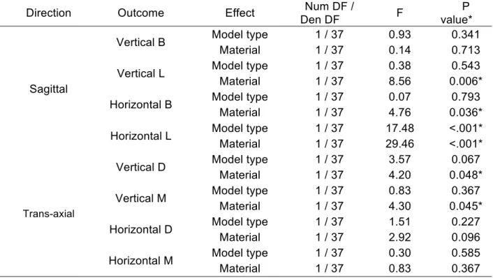
Table 7 shows the result of linear mixed models with compound symmetric covariance structure for each outcome by direction. For all outcomes, the marginal gap was larger for zirconia than for lithium disilicate. Table 8 shows the logarithmic transformations that were applied (log10) in the statistical analysis and the re-transformed raw values for easier visualization and interpretability of the data.
Table 7. Result of linear mixed models with compound symmetric covariance structure for each outcome by direction
Direction Outcome Effect Den DF Num DF / F value* P
Sagittal
Vertical B Model type 1 / 37 0.93 0.341
Material 1 / 37 0.14 0.713
Vertical L Model type 1 / 37 0.38 0.543
Material 1 / 37 8.56 0.006*
Horizontal B Model type 1 / 37 0.07 0.793
Material 1 / 37 4.76 0.036*
Horizontal L Model type 1 / 37 17.48 <.001*
Material 1 / 37 29.46 <.001*
Trans-axial
Vertical D Model type 1 / 37 3.57 0.067
Material 1 / 37 4.20 0.048*
Vertical M Model type 1 / 37 0.83 0.367
Material 1 / 37 4.30 0.045*
Horizontal D Model type 1 / 37 1.51 0.227
Material 1 / 37 2.92 0.096
Horizontal M Model type 1 / 37 0.30 0.585
Material 1 / 37 0.83 0.367
There was a statistically significant difference between the marginal misfit of zirconia and lithium disilicate in the following surfaces: horizontal buccal (P=0.036), and lingual (P<0.001) surfaces of the restorations; the vertical lingual (P=0.006), distal (P=0.048) and mesial (P=0.045) surfaces.
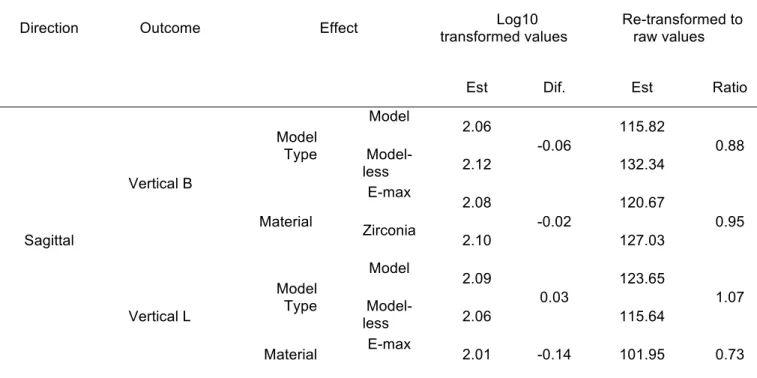
Table 8 shows the least square means from the linear mixed models surfaces according to the different directions and outcomes. The average marginal gap as determined by micro-CT analysis for the surfaces that showed statistically significant results were estimated as follows: the estimated horizontal marginal gap of the buccal view was 133.9 µm for E-max and 156.3 µm for zirconia; the horizontal marginal gap in the lingual surface was 122.7 µm and 165.4 µm for E-max and zirconia, respectively. On the other hand the vertical marginal gap in the lingual view was 101.9 µm for lithium disilicate and 140.2 µm for zirconia; the marginal gap in the distal surface was 104.6 µm for lithium disilicate and 126.4 µm for zirconia; the marginal gap in the mesial surface was 111.8 µm for lithium disilicate and 142.9 µm respectively. The percentage of restorations that were under 120 microns was 48% for E-max and 25% for Zirconia restorations.
Table 8. Least square means from the linear mixed models.
Direction Outcome Effect transformed values Log10 Re-transformed to raw values
Est Dif. Est Ratio
Sagittal Vertical B Model Type Model 2.06 -0.06 115.82 0.88
Model-less 2.12 132.34
Material E-max 2.08 -0.02 120.67 0.95 Zirconia
2.10 127.03
Vertical L Model Type Model 2.09 0.03 123.65 1.07
Model-less 2.06 115.64
Zirconia
2.15 140.25
Horizontal B
Model Type Model 2.16 0.01 146.05 1.02
Model-less 2.16 143.35
Material E-max 2.13 -0.07 133.91 0.86 Zirconia
2.19 156.35
Horizontal L
Model Type Model 2.20 0.10 159.85 1.26
Model-less 2.10 127.06
Material E-max 2.09 -0.13 122.77 0.74 Zirconia
2.22 165.42
Trans-axial Vertical D Model Type Model 2.10 0.08 125.55 1.19
Model-less 2.02 105.39
Material E-max 2.02 -0.08 104.62 0.83 Zirconia
2.10 126.47
Vertical M Model Type Model 2.08 -0.05 119.78 0.90
Model-less 2.13 133.44
Material E-max 2.05 -0.11 111.84 0.78 Zirconia
2.16 142.92
Horizontal D Model Type Model 2.19 0.04 153.57 1.09
Model-less 2.15 141.22
Material E-max 2.14 -0.05 138.90 0.89 Zirconia
2.19 156.13
Horizontal M Model Type Model 2.12 -0.02 132.31 0.96
Model-less 2.14 137.25
Material E-max 2.14 0.03 138.90 1.06 Zirconia
2.12 130.74
In regards to the fabrication technique, the two model types differed significantly only for horizontal lingual measures (p<0.001) in the sagittal direction being the model-less technique better than the model technique.
Table 9 shows the mean difference and paired t-test from the reliability analysis. The intraclass correlation coefficients results were 0.99 indicating high concordance between
measurements beyond that expected by chance and there is no statically significant values from the paired tests indicating that there is no systematic bias and high consistency between
measurements.
Table 9. Mean difference and paired t-test.
Direction Variable
Original (matched
to Reassessment) Reassessment Paired t-test
Mean Dev Std Mean Dev Std t DF P
Sagittal
VBD 147.55 95.47 148.29 92.87 -0.66 39 0.51
VLM 142.87 97.19 141.97 98.17 0.51 39 0.62
HBD 151.30 48.55 153.32 47.95 -2.03 39 0.05
HLM 156.32 78.47 156.68 77.04 -0.27 39 0.79
Trans-axial
VBD 136.37 79.38 137.62 77.73 -1.00 39 0.33
VLM 139.51 94.39 138.78 94.12 0.63 39 0.53
HBD 157.19 61.92 154.89 60.68 1.30 39 0.20
DISCUSSION
This research consisted in the in vitro evaluation of lithium disilicate and zirconia all-ceramic restorations because these materials represent two of the most used ceramic materials in dentistry. It also evaluated the effect of using a printed model versus a fully digital approach for crown fabrication. The null hypothesis stating that the difference between materials would not be statistically significant in regards to the marginal fit of the restorations was rejected.
Data from this study revealed statistically significant differences in marginal adaptation when restorations were fabricated with zirconia or lithium disilicate. The results indicated that
compared to zirconia, lithium disilicate crowns fabricated using a CAD/CAM approach presented less marginal gap (better adaptation). Thus, it was expected that lithium disilicate would have a superior fit compared to zirconia because the last one exhibits more shrinking compensation when its sintered; in addition to the fact that lithium disilicate restorations were fabricated thru the complete Cerec workflow in contrast to the system integration of Cerec and Roland DWX 50 milling machine used for the fabrication of zirconia crowns which has not yet being studied and for which no previous research has been reported.
One possible explanation may reside in the fact that the level of expertise of the operators using the Cerec intraoral scanner and CAD system was not high and they did not have plenty of experience. There was no standardization of the digital impression process technique or margin marking during the clinical procedure other than following the manufactures recommendations. The quality of acquisition and processing of the scanned data in conjunction with the clinical and technical experience with the CAM/CAM system and its integration is a key factor for restoration success when using CAD/CAM technology (Martin, 2000).
In this study an axial reduction with heavy chamfer finish line was chosen because
according to most studies there is no significant difference in the marginal gap when a chamfer and shoulder margin configurations are used (Baig, et al. 2010). In a study by Cerutti, et al. (2014) the comparison of the marginal fit of CAD/CAM crown copings using chamfer and
shoulder preparations showed no significant differences regarding the dimension of the gap and both are able to help clinicians obtaining acceptable marginal fit with zirconia copings. In
contrast to this results Bindl, et al. (2007) observed better marginal adaptation when using rounded shoulder configurations than with chamfer finish lines preparations, however, they also noticed a smaller internal gap with chamfer designs and this findings could suggest that the preparation form could have influence the results.
The fabrication process when milling zirconia versus lithium disilicate restorations is a factor that could lead to a different marginal adaptation. The milling process of zirconia is done in a dry
The potential differences between the different milling machines during the CAM fabrication phase is a variable that has to be consider. The use of different nesting programs, tool path determination, integral dimensional constraints and calibration effects of the individual mills could lead to different marginal adaptation results. According to the scientific guidelines of several manufactures different milling systems could lead to different marginal adaptation that can vary as a result of differences in the dimension on the milling tools, the number of axis, and the selected milling strategy. According to the manufacture Ivoclar Vivadent, “highly aggressive milling strategies can induce surface flaws that can potentially chip marginal areas, although the proper milling strategy is integrated into the software of the approved milling machines, users can try to speed the process by “fooling” the software into thinking that a different material is being milled.” Faster milling strategies are almost always detrimental and should be avoided.
Furthermore, the milling process and the preparation design may also affect the internal adaptation of the crown; the narrowest possible diameter of the preparation is determined by the smallest diameter of the bur used for milling the internal surface; as a consequence in structures that are smaller than the narrowest bur diameter, more internal material may be removed than necessary affecting the fit of the restoration and resulting in larger internal gaps. The same phenomenon could happen when selecting between a detailed or regular milling processes, as the path of the burs will determine how detailed the restoration is going to fit (Reich, et al. 2005).
The dimensional inaccuracies associated with shrinking during the sintering process and
The restoration parameters during the design also influence the marginal adaptation of CAD/CAM all ceramic restorations; for example, the virtual configuration of the die spacer between the tooth and the restorations is essential for the accuracy of the marginal adaptation. Weittstein et al. (2009) demonstrated that the difference of fit between CAD/CAM restorations is directly related to the gap parameters from the computer design and also related to the intrinsic properties of the CAD/CAM system; the die spacer should be uniform and facilitate seating; several studies have looked at the effect of die spacer on the retention and physical properties of crowns (Campbell, 1990). In this study both laboratories used the default internal parameters of 40 microns for crown fabrication proposed by the In-Lab software. Previous studies have stated that chair-side milling has demonstrated the ability to produce marginal and internal adaptations within 50 to 100 microns (Mörmann, 2006) when using the same parameters that are proposed in the software. In a study by Nakamura, et al (2003), the marginal and internal fit of all ceramic crowns was examine using three different luting space settings (10, 30 and 50 microns); marginal gaps of a luting space of 10 microns tend to show greater marginal gaps than when it was set at 30 or 50 microns; crowns with a luting space of 30 and 50 microns showed a good fit regardless of the occlusal convergence angle of the abutments.
In this study all the restorations were cemented to each preparation adding another possible factor that could affect the marginal adaptation of the restorations. As stated in previous studies when restorations are cemented the cement space should be uniform and facilitate seating
without compromising the marginal adaptation (May, et al. 1998). The specimens could
the different zirconia systems they used, having the resin cement the larger marginal
discrepancies when compared to glass-ionomer cement. Experimental in-vitro studies should evaluate the restorations before and after cementation to be able to discard the fact that the cement type, viscosity or technique could make a difference during marginal adaptation.
In vitro results should be viewed cautiously because the testing methods does not completely represent what happens in a clinical environment. The approach employed in the present study was to somehow recreate a more realistic environment to evaluate restorations made by clinicians in a daily basis using different samples; for each sample a different scan and computerized design was performed. The majority of the investigations focus primarily in
achieving the best possible accuracy that can be obtained from the systems under ideal conditions eliminating the influence of common clinical errors. On the other hand, both groups had broad standard deviations values and the data was difficult to interpret without logarithmic transformations. Future studies should include and correlate the materials and systems used in this study in more standardized environments that could help correlate the results.
Evaluation methods such as 3D reconstruction, direct viewing and Micro-CT evaluation provide non-destructive methods. Previous research studies have been done using techniques that could represent measurement of distorted processed samples, which have incorporated errors. The angular measurement as proposed by Holmes, et al. (1989) was selected because marginal misfit can result in vertical and/or horizontal gaps or a combination of them. When
comparing the data with previous studies that used CEREC, most investigators assessed inlay and onlay restorations on previous CEREC models before CEREC Bluecam. Recent
milling machine in combination with CEREC or any other digital impression system no research was found. The different techniques that have been used to analyze marginal adaptation present a variety of results even when similar experimental methods are used, different
methods including micro-CT avoid distortions and offer very high resolution; as a consequence the methods used for specimen evaluation could play a major role on the data obtained and not only the accuracy of the marginal adaptation. The results obtained for the model and model-less technique showed that there were no significant differences. During the fabrication process dental laboratories use stone or printed models as a traditional method to check proximal contacts, occlusal contacts and contours. The digital workflow and fabrication process is very standardized and predictable; most digital design programs can be learned in days and most design softwares have tools that facilitate the design process (Fasbinder, 2012). When comparing digital versus traditional impressions the time required to take impressions can be reduced because rescans of the missing areas can be acquired in 1 to 2 minutes in comparison to retaking traditional impressions with rubber base materials which usually takes around 5-7 minutes for each impression using polyvinyl siloxane impression materials (Lee, et al. 2013). It is important to mention that according to different studies is not uncommon to find different distortions like drags, voids or tears in traditional impressions (Wassell, et al. 2002).
In addition, digital dentistry represents a great tool in oral health education for evaluation of restorations during the fabrication process as it provides ways view restoration in big screens
and also quantifies proximal and occlusal contacts. Using digital impressions could also reduce waste, there are no concerns about manipulation or distortion of materials and avoid the need for disinfection materials; it also has the advantage that the data can be stored in a computer and no duplicates are needed. Different studies have shown that the accuracy of digital
CONCLUSION
FIGURES
Figure 2. Crown design using the In-Lab software (Sirona Dental)
Figure 3. Squematic representation of the 26 images selected for analysis in the micro-CT
Figure 4. Micro computed tomography, sagittal image of crown at 100x magnification.
Figure 5. A) Schematic representation of the vertical misfit to be evaluated in the
micro-CT. B) Horizontal misfit.
Figure 6. Graphic representation of the specimen medians for E-max model group.
Figure 8. Graphic representation of the specimen medians for zirconia model group.
REFERENCES
3Shape dental solutions. Available: www.3shape.com
Anusavice, K. Phillips' Science of Dental Materials, 12edition. 2014.
Att W, Komine F, Gerds T, Strub JR. Marginal adaptation of three different zirconium dioxide three-unit fixed den- tal prostheses. J Prosthet Dent. 2009;101:239–247.
Baig, M. Tan, K. Nicholls, J. Evaluation of marginal fit of zirconia ceramic computer aided machined (CAM) crown system. J of Prosth Dent. 2010 : 216-227.
Batson E, Cooper LF, Duqum I, Mendonnd G. Clinical outcomes of three different crown systems using CAD/CAM technology. J Prosthet Dent. 2014. In press.
Bindl A, Mormann WH. Marginal and internal fit of all-ceramic CAD/CAM crown- copings on chamfer preparations. J Oral Rehabil 2005;32:441-7.
Bindl A, Mormann WH. Survival rate of mono-ceramic and ceramic-core CAD/ CAM-generated anterior crowns over 2-5 years. Eur J Oral Sci 2004.
Bindl A, Mormann WH. Fit of all-ceramic posterior fixed partial denture frameworks in vitro. Int J Periodontics Restorative Dent. 2007;27(6):567–75.
Boening KW, Wolf BH, Schmidt AE, Kastner K, Walter MH. Clinical fit of Procera AllCeram crowns. J Prosthet Dent 2000;84:419-24.
Borba, M., Cesar, P. F., Griggs, J. A., & Della Bona, Á M., Cesar, P. F., Griggs, J. A., & Della Bona, ona, using CAD/CAM technology. J Prosthet Dent.
BruxZir Mill. Glidewell laboratories. Available: www.glidewelldental.com
CAD/CAM solutions for the dental Laboratory. InLab the art of innovative dental technology. www.sirona.com
CAD/CAM Support. Wieland Dental. Available www.wieland-dental.com
Campbell, S. D. (1990). Comparison of conventional paint-on die spacers and those used with the all-ceramic restorations. J Prosthet Dent, 63(2), 151-155.
Ceramill Motion 2. Amann Girbach. Available: www.amanngirbach.com
Cerutti, F. Augusti, G. Cerutti, A. Augusti, D. Comparison of marginal fit of Lava CAD/CAM crown copings with two finish lines. The Int Journal of Esthetic Dent. 2014, 9(3): 426-435.
Chang JC, Hart DA, Estey AW, Chan JT. Tensile bond strengths of five luting agents to two CAD-CAM restorative materials and enamel. J Prosthet Dent 2003.
Charlton DG, Robert HW, Tiba A. Measurement of select physical and mechanical properties of 3 machinable ceramic materials. Quintessence Int. 2008.
Christensen GJ. Marginal fit of gold inlay castings. J Prosthet Dent 1966. 297- 305.
Colpani JT, Borba M, Della Bona A. Evaluation of mar- ginal and internal fit of ceramic crown copings. Dent Mater. 2013; 29:174–180.
Cooper, L. Direct ceramic restoration using digital technologies. International dentistry Australian edition VOL. 7, NO. 1. 2011. 32-35.
Da Costa JB, Pelogia F, Hagedorn B, Ferracane JL. Evaluation of different methods of optical impression making on the marginal gap of onlays created with CEREC 3D. Oper Dent 2010;35:324-9.
De Vico G, Ottria L, Bollero P, Bonino M, Cialone M, Bar- lattani A Jr et al. Aesthetic and functionality in fixed pros- thodontic: sperimental and clinical analysis of the CAD- CAM systematic 3Shape. Oral Implantol. 2008; 1:104–115.
Delcam CAD/CAM software solutions. Available: www.delcam.com
Denissen H, Dozic A, van der Zel J, van Waas M. Marginal fit and short-term clinical
performance of porcelain-veneered CICERO, CEREC, and Procera onlays. J Prosthet Dent 2000;84:506-13.
Dental milling solutions. D5 Dental Mill. Available: www.datron.com
Esquivel-Upshaw JF, Chai J, Sansano S, Shonberg D. Resistance to staining, flexural strength, and chemical solubility of core porcelains for all-ceramic crowns. Int J Prosthodont 2001.
Euen R, Figueras-ras-In O, Cabratosa-Termes J, Oliver-Parra R. Marginal adaptation of zirconium dioxide copings: Influence of the CAD/CAM system and the finish line design. J Prosthet Dent 2014 Jan 17. http://www.ncbi.nlm.nih.gov/pubmed/24445027.
Fasbinder DJ. Restorative material options for CAD/CAM restorations. Compend Contin Educ Dent 2002.
Felton, D. Kanoy, B. Bayne, M. Wirthman, B. Effect of in vivo crown margin discrepancies on periodontal health. J of Prosth Dent. 1991.
Fradeani M, D’Amelio M, Redemagni M, Corrado M. Five-year follow-up with Pro- cera all-ceramic crowns. Quintessence Int 2005.
Fritzsche G. Treatment of a single-tooth gap with a Cerec 3D crown on an im- plant: A case report. Int J Comput Dent 2004.
Gehrt, M., Wolfart, S., Rafai, N., Reich, S., & Edelhoff, D. (2013). Clinical results of lithium-disilicate crowns after up to 9 years of service. Clinical Oral Investigations, 17(1), 275–84.
Guazzato M, Proos K, Quach L, Swain MV. Strength, reliability and mode of fracture of bilayered porcelain/zirconia (Y-TZP) dental ceramics. Biomaterials 2004.
Gupta TK, Bechtold JH, Kuznickie RC, Cadoff LH, Rossing BR. Stabilization of tetragonal phase in polycrystalline zirconia. J Mater Sci 1978;13:1464.
Hamza TA, Ezzat HA, El-Hossary MM, Katamish HA, Shokry TE, Rosenstiel SF .Accuracy of ceramic restorations made with two CAD/CAM systems. J Prosthet Dent 2013;109:83-7. http://www.ncbi.nlm.nih.gov/pubmed/23395333.
Hertlein G. Kramer M, Sprengart T, et al. Milling time vs marginal fit of CAD/CAM manufactured zirconia restorations. J. Dent Res 2003; 82:194.
Hmaidouch R, Neumann P, Mueller W-D. Influence of preparation form, luting space setting and cement type on the marginal and internal fit of CAD/CAM crown copings. Int J Comput Dent. 2011;14:219–226.
Holmes JR, Bayne SC, Holland GA, Sulik WD. Considerations in measurement of marginal fit. J Prosthet Dent 1989; 62:405- 8.
Holmes JR, Sulik WD, Holland GA, Bayne SC. Marginal fit of castable ce- ramic restorations. J Prosthet Dent 1992;67:594-9.
Hwang, Y. C., Park, Y. S., Kim, H. K., Hong, Y. S., Ahn, J. S., & Ryu, J. J. (2013). The Evaluation of Working Casts Prepared from Digital Impressions.
idataresearch.com website. iDataResearchInc.2011.U.S.Dental Prosthetics and CAD/CAM Devices Market.
In-sung, Y. Yang, J. Lee, J. In votro marginal fit of three all ceramic crown systems. J of Prosth Dent. 2003. 459-464.
InLab Labside Solutions and CAD/CAM materials. Available: www.Sirona.com
Inside Dental Technology. Product iNavigator 2013. Available www.insidedentaltech.com.
Isenberg, P. Essig, ME. Leinfelder, KF. Three year clinical evaluation of CAD/CAM restorations. J Esthetic Dent. 1992.
Kelly JR, Denry IL. Stabilized zirconia as a structural ceramic: an overview. Dent Mater 2008;24:289–98.
Kelly, J. R. (2004). Dental ceramics: current thinking and trends. Dent Clin North Am.
Kelly, R. Nishimura, I. Campbell, S. Ceramics in dentistry: Historical roots and current perspectives. Journal of Prosthetic Dent. Vol 75. N. 1. 1996.
Keshvad A, Hooshmand T, Asefzadeh F, Khalilinejad F, Alihemmati M, Van Noort R. Marginal gap, internal fit, and fracture load of leucite-reinforced ceramic inlays fabricated by CEREC inLab and hot-pressed techniques. J Prosthodont 2011;20:535-40.
Kosmac T, Oblak C, Jevnikar P, Funduk N, Marion L. The effect of surface grinding and
Kurbad A, Reichel K. Multicolored ceramic blocks as an esthetic solution for anterior restorations. Int J Comput Dent 2006.
Lava milling system. 3M ESPE. Available: solutions.3m.com
Lee, S. J., & Gallucci, G. O. (2013). Digital vs. conventional implant impressions: efficiency outcomes. Clinical Oral Implants Research, 24(1), 111-115.
Lee, K. Park, C. Kim, K. Kwon, T. Marginal and internal fit of all ceramic crowns fabricated with two different CAD/CAM systems. Dent Materials J. 2008; 27(3): 422-426.
Lin MT, Sy-Munoz J, Munoz CA, Goodacre CJ, Naylor WP. The effect of tooth preparation form on the fit of Procera copings. Int J Prosthodont. 1998;11(6):580–90.
Luthardt RG, Sandkuhl O, Reitz B. Zirconia- TZP and alumina--advanced technologies for the manufacturing of single crowns. Eur J Prosthodont Restor Dent 1999.
Martin N, Jedynakiewicz NM. Interface di- mensions of CEREC-2 MOD inlays. Dent Mater 2000
Martinez, F. Suarez, M. Rivera, B. Pradies, G. Evaluation of the absolute marginal discrepancy of zirconia based ceramic copings. J of Prosth Dent. 2011 :108-114.
Martinez-Rus, F. Suarez, M. Rivera, B. Pradies, G. Influence of CAD/CAM systems and cement selection on marginal discrepancy of zirconia based ceramic crowns. Am J Dent.
2012;25(2):67-72
Matta RE, Schmitt J, Wichmann M, Holst S. Circumferen- tial fit assessment of CAD/CAM single crowns–a pilot investigation on a new virtual analytical protocol. Quintessence Int. 2012; 43:801–809.
May KB, Russel MM, Razzoog ME, et al. Precession of fit; the procera all Ceram crown. J Prosthet Dent 1998.
May KB, Russell MM, Razzoog ME, Lang BR. Precision of fit: the Procera AllCeram crown. J Prosthet Dent 1998.
McLaren, E. Sameer, P. Cerec materials overview. Different selections for milling restorations. Available at Cerecdoctors.com. 2013.
McLean JW, von Fraunhofer JA. The esti- mation of cement film thickness by an in vivo technique. Br Dent J 1971.
McLean JW, von Fraunhofer JA. The estimation of cement film thickness by an in vivo technique. Br Dent J 1971;131:107-11.
McLean JW, von Fraunhofer JA. The estimation of cement film thickness by an in vivo technique. Br Dent J 1971;131:107–111. 9.
Mehl, A., Ender, A., Mormann, W., & Attin, T. (2009). Accuracy testing of a new intraoral 3D camera. Int J Comput Dent, 12(1), 11-28.
Miyazaki T, Hotta Y, Kunii J, Kuriyama S, Tamaki Y. A review of dental CAD/CAM: current status and future perspectives from 20 years of experience. Dent Mat Journal 2009; 28: 44-56.
Mormann WH. The evolution of the CEREC system. J Am Dent Assoc. 2006;137: 7s-13s.
Nakamura, T. Dei, N. Kojima, T. Wakabayashi, K. Marginal and internal fit of Cerec 3 CAD/CAM all ceramic crowns. Int Journal of Prosth. 2005.
Nawafleh, N. Mack, F. Evans, J. Mackay, J. Hatamleh, M. Accuracy and reliability of methods to measure marginal adaptation of crowns and FPDs: a literature review. J Prosth 2013. 22(5):419-28
Neves FD, Prado CJ, Prudente MS, Carneiro TAPN, Zancope K, Davi LR, Mendonçe G, Cooper LF, Soares CJ. (2014) Marginal fit evaluation with microcomputed tomography of lithium disilicate crowns fabricated by chairside CAD/CAM systems and the heat-pressing technique. J Prosthet Dent In Press.
Nobelprocera CAD/CAM. Nobel Biocare. Available: www.nobelbiocare.com
Pallesen U, van Dijken JW. An 8-year evaluation of sintered ceramic and glass ceramic inlays processed by the Cerec CAD/CAM system. Eur J Oral Sci 2000.
Piconi C, Maccauro G. Zirconia as a ceramic biomaterial. Biomaterials 1999; 20:1–25.
Piwowarczyk A, Ottl P, Lauer HC, Kuretzky T. A clinical report and overview of scien- tific studies and clinical procedures con- ducted on the 3M ESPE Lava All-Ceramic System. J
Prosthodont 2005.
Pjetursson, B. E., Sailer, I., Zwahlen, M., & Hämmerle, C. H. F. (2007). A systematic review of the survival and complication rates of all-ceramic and metal-ceramic reconstructions after an observation period of at least 3 years. Part I: Single crowns. Clinical Oral Implants Research, 18 Suppl 3, 73–85.
Planmeca technologies. Available: www.e4d.com
Rahme, H. Y., Tehini, G. E., Adib, S. M., Ardo, A. S., & Rifai, K. T. (2008). In vitro evaluation of the "replica technique" in the measurement of the fit of Procera crowns. J Contemp Dent Pract, 9(2), 25-32.
Raigrodski AJ. Contemporary all-ceramic fixed partial dentures: a review. Dent Clin North Am 2004.
Reich SM, Peltz ID, Wichmann M, Estafan DJ. A comparative study of two CEREC software systems in evaluating manufac- turing time and accuracy of restorations. Gen Dent 2005.
Reich, S. Wichmann, M. Nkenke, E. Proeschel, P. Clinical fit of all ceramic three unit fixed partial dentures generated with three different CAD/CAM systems. Eur J Oral Sci. 2005; 113: 174-179.
Rieth PH, Reed JS, Naumann AW. Fabrication and flexural strength of ultra-fine grained yttria-stabilised zirconia. Bull Am Ceram Soc 1976;55:717.
Schaefer, O., Schmidt, M., Goebel, R., & Kuepper, H. (2012). Qualitative and quantitative three-dimensional accuracy of a single tooth captured by elastomeric impression materials: An in vitro study. J Prosthet Dent, 108(3), 165-172.
Schwartz NL, Whitsett LD, Berry TG, Steward JL. Unserviceable crowns and fixed partial dentures: Life span and causes for loss of serviceability. J Am Dent Assoc 1970;81:1395– 1401.
Shen, J. Kosmac, T. Advanced Ceramics for Dentistry. El Savier. 2014: 227-248.
Sorensen JA, McLaren E, Avera SP. Marginal fidelity and microleak- age of ceramic inlay systems [Abstract]. J Dent Res 1994.
Souza ROA, O€zcan M, Pavanelli CA, Buso L, Lombardo GHL, Michida SMA et al. Marginal and internal discrepan- cies related to margin design of ceramic crowns fabricated by a
CAD/CAM system. J Prosthodont. 2012;21:94–100.
Straumann CARES Digital Solutions. Straumann CAD/CAM. Available: www.straumann-cares-digital-solutions.com
Sundh A, Sjogren G. A comparison of frac- ture strength of yttrium-oxide- partially-sta- bilized zirconia ceramic crowns with varying core thickness, shapes and veneer ceramics. J Oral Rehabil 2004.
Syrek, A., Reich, G., Ranftl, D., Klein, C., Cerny, B., & Brodesser, J. (2010). Clinical evaluation of all-ceramic crowns fabricated from intraoral digital impressions based on the principle of active wavefront sampling. Journal of Dentistry 2010.
The complete software solution for digital dentistry. Exocad. Available: www.exocad.com. Tinschert J, Natt G, Mautsch W, Spie- kermann H, Anusavice KJ. Marginal fit of alumina-and
zirconia-based fixed partial dentures produced by a CAD/CAM system. Oper Dent 2001.
Tinschert J, Zwez D, Marx R, Anusavice KJ. Structural reliabil- ity of alumina-, feldspar-, leucite-, mica- and zirconia-based ceramics. J Dent 2000;28:529–535.
Trifkovic B, Budak I, Todorovic A, Hodolic J, Puskar T, Jevremovic D, et al. Application of replica technique and SEM in accuracy measurement of ceramic crowns. Measurement Science Review 2012.
Vander Zel J, Vlaar S, Ruiter W, Davidsonc. The CICERO system for CAD/CAM fabrication of full ceramic crown. J Prosthet Dent 2001; 85:261- 67.
Vitablocs® Mark II for Cerec. Material Science and Clinical Studies. VidentTM Scientific Brochure; 2000.
Wassell, R. W., Barker, D., & Walls, A. W. (2002). Crowns and other extra-coronal restorations: impression materials and technique. Br Dent J, 192(12), 679-684, 687- 690.
Website idataresearch.net; iData Research Inc. 2011.U.S. Dental Prosthetics and CAD/CAM Devices Market.