Feature History
Release Modification
12.0(7)XE This feature was introduced with support for the following platforms: • Catalyst 6000 Family Switches with Supervisor Engine 1
• Cisco 7200 Series Routers
The following functions were provided:
• Algorithms for Server Load Balancing, page 5 • Automatic Server Failure Detection, page 6 • Automatic Unfail, page 6
• Bind ID Support, page 7
• Client-Assigned Load Balancing, page 7
• Delayed Removal of TCP Connection Context, page 7 • Dynamic Feedback Protocol for IOS SLB, page 8 • Maximum Connections, page 10
• Port-Bound Servers, page 12 • Slow Start, page 15
• Sticky Connections, page 15 • SynGuard, page 15
• TCP Session Reassignment, page 16 12.1(1)E The following functions were added:
• Alternate IP Addresses, page 6 • Content Flow Monitor Support, page 7
• Network Address Translation (NAT) and Session Redirection, page 11—Server NAT
• Redundancy Enhancements, page 13—Stateless Backup • Transparent Webcache Load Balancing, page 16
This document describes the Cisco IOS Server Load Balancing (SLB) feature in Cisco IOS Release 12.1(9)E. It includes the following sections:
• Overview of the IOS SLB Feature, page 3 • Functions and Capabilities, page 4 • Benefits, page 17
• Restrictions, page 17
• Related Features and Technologies, page 20 • Related Documents, page 20
• Supported Platforms, page 20
page 11—Server and Client NAT
• Redundancy Enhancements, page 13—Stateless and Stateful Backup 12.1(3a)E The following functions were added:
• Firewall Load Balancing, page 8
• Probes, page 12—HTTP and Ping Probes • Protocol Support, page 13
• Redundancy Enhancements, page 13—Stateless and Stateful Backup, and Active Standby
• WAP Load Balancing, page 16 12.1(5a)E The following functions were added:
• Avoiding Attacks on Server Farms and Firewall Farms, page 6 • Probes, page 12—HTTP, Ping, and WSP Probes
12.1(5)T The Cisco IOS Release 12.1(1)E feature was migrated to Cisco IOS Release 12.1(5)T, supporting Cisco 7200 Series Routers only. 12.1(7)E Support for the following platforms was added:
• Cisco 7100 Series Routers The following functions were added:
• Multiple Firewall Farm Support, page 10 • Route Health Injection, page 14
12.1(8a)E Support for the following platform was added:
• Catalyst 6000 Family Switches with Supervisor Engine 2 The following functions were added:
• Backup Server Farms, page 7
• DFP Agent Subsystem Support, page 8 12.1(9)E The following functions were added:
• Supported Standards, MIBs, and RFCs, page 21 • Configuration Tasks, page 21
• Monitoring and Maintaining the IOS SLB Feature, page 40 • Configuration Examples, page 41
• Command Reference, page 91
• FAQ (Frequently Asked Questions), page 212 • Glossary, page 214
Overview of the IOS SLB Feature
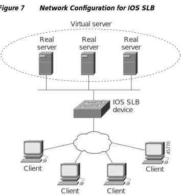
The IOS SLB feature is an IOS-based solution that provides IP server load balancing. Using the IOS SLB feature, you can define a virtual server that represents a group of real servers in a cluster of network servers known as a server farm. In this environment, the clients connect to the IP address of the virtual server. When a client initiates a connection to the virtual server, the IOS SLB function chooses a real server for the connection based on a configured load-balancing algorithm.
Note IOS SLB does not support load balancing of flows between clients and real servers that are on the same local area network (LAN) or virtual LAN (VLAN). The packets being load balanced cannot enter and leave the load-balancing device on the same interface.
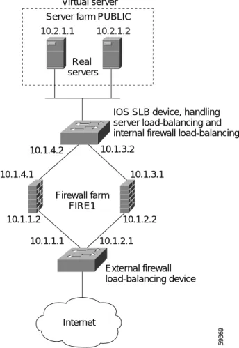
IOS SLB also provides firewall load balancing, which balances flows across a group of firewalls called a firewall farm.
Figure 1 illustrates a logical view of a simple IOS SLB network. Figure 1 Logical View of IOS SLB
Client Client Client Client IOS SLB device Real server Real server Virtual server Real server 45770
Functions and Capabilities
This section describes the following functions and capabilities provided by IOS SLB.
Note Some IOS SLB functions are specific to one platform and are not described in this feature module. For information about those functions, refer to the appropriate platform-specific documentation.
• Algorithms for Server Load Balancing, page 5 • Alternate IP Addresses, page 6
• Automatic Server Failure Detection, page 6 • Automatic Unfail, page 6
• Avoiding Attacks on Server Farms and Firewall Farms, page 6 • Backup Server Farms, page 7
• Bind ID Support, page 7
• Client-Assigned Load Balancing, page 7 • Content Flow Monitor Support, page 7
• Delayed Removal of TCP Connection Context, page 7 • DFP Agent Subsystem Support, page 8
• Dynamic Feedback Protocol for IOS SLB, page 8 • Firewall Load Balancing, page 8
• GPRS Load Balancing, page 9 • Maximum Connections, page 10
• Multiple Firewall Farm Support, page 10
• Network Address Translation (NAT) and Session Redirection, page 11 • Port-Bound Servers, page 12
• Probes, page 12
• Protocol Support, page 13
• Redundancy Enhancements, page 13 • Route Health Injection, page 14 • Slow Start, page 15
• Sticky Connections, page 15 • SynGuard, page 15
• TCP Session Reassignment, page 16
• Transparent Webcache Load Balancing, page 16 • WAP Load Balancing, page 16
Algorithms for Server Load Balancing
IOS SLB provides the following load-balancing algorithms: • Weighted Round Robin, page 5
• Weighted Least Connections, page 5
You can specify one of these algorithms as the basis for choosing a real server for each new connection request that arrives at the virtual server.
Weighted Round Robin
The weighted round robin algorithm specifies that the real server used for a new connection to the virtual server is chosen from the server farm in a circular fashion. Each real server is assigned a weight, n, that represents its capacity to handle connections, as compared to the other real servers associated with the virtual server. That is, new connections are assigned to a given real server n times before the next real server in the server farm is chosen.
For example, assume a server farm comprised of real server ServerA with n = 3, ServerB with n = 1, and ServerC with n = 2. The first three connections to the virtual server are assigned to ServerA, the fourth connection to ServerB, and the fifth and sixth connections to ServerC.
Note Assigning a weight of n=1 to all of the servers in the server farm configures the IOS SLB device to use a simple round robin algorithm.
GPRS load balancing requires the weighted round robin algorithm. A server farm that uses weighted least connections can be bound to a virtual server providing GPRS load balancing, but you cannot place the virtual server INSERVICE. If you try to do so, IOS SLB issues an error message.
Weighted Least Connections
The weighted least connections algorithm specifies that the next real server chosen from a server farm for a new connection to the virtual server is the server with the fewest active connections. Each real server is assigned a weight for this algorithm, also. When weights are assigned, the server with the fewest connections is based on the number of active connections on each server, and on the relative capacity of each server. The capacity of a given real server is calculated as the assigned weight of that server divided by the sum of the assigned weights of all of the real servers associated with that virtual server, or n1/(n1+n2+n3...).
For example, assume a server farm comprised of real server ServerA with n = 3, ServerB with n = 1, and ServerC with n = 2. ServerA would have a calculated capacity of 3/(3+1+2), or half of all active connections on the virtual server, ServerB one-sixth of all active connections, and ServerC one-third of all active connections. At any point in time, the next connection to the virtual server would be assigned to the real server whose number of active connections is farthest below its calculated capacity.
Note Assigning a weight of n=1 to all of the servers in the server farm configures the IOS SLB device to use a simple least-connection algorithm.
Alternate IP Addresses
IOS SLB enables you to telnet to the load-balancing device using an alternate IP address. To do so, use either of the following methods:
• Use any of the interface addresses to telnet to the load-balancing device. • Define a secondary IP address to telnet to the load-balancing device.
This function is similar to that provided by the LocalDirector (LD) Alias command.
Automatic Server Failure Detection
IOS SLB automatically detects each failed Transmission Control Protocol (TCP) connection attempt to a real server, and increments a failure counter for that server. (The failure counter is not incremented if a failed TCP connection from the same client has already been counted.) If a server’s failure counter exceeds a configurable failure threshold, the server is considered out of service and is removed from the list of active real servers.
Automatic Unfail
When a real server fails and is removed from the list of active servers, it is assigned no new connections for a length of time specified by a configurable retry timer. After that timer expires, the server is again eligible for new virtual server connections and IOS SLB sends the server the next qualifying connection. If the connection is successful, the failed server is placed back on the list of active real servers. If the connection is unsuccessful, the server remains out of service and the retry timer is reset.
Avoiding Attacks on Server Farms and Firewall Farms
IOS SLB relies on a site’s firewalls to protect the site from attacks. In general, IOS SLB is no more susceptible to direct attack than is any switch or router. However, a highly secure site can take the following steps to enhance its security:
• Configure real servers on a private network to keep clients from connecting directly to them. This ensures that the clients must go through IOS SLB to get to the real servers.
• Configure input access lists on the access router or on the IOS SLB device to deny flows from the outside network aimed directly at the interfaces on the IOS SLB device. That is, deny all direct flows from unexpected addresses.
• To protect against attackers trying to direct flows to real or nonexistent IP addresses in the firewall subnet, configure the firewalls in a private network.
• Configure firewalls to deny all unexpected flows targeted at the firewalls, especially flows originating from the external network.
Backup Server Farms
A backup server farm is a server farm that can be used when none of the real servers defined in a primary server farm is available to accept new connections. When configuring backup server farms, keep in mind the following considerations:
• A server farm can act as both primary and backup at the same time.
• The same real server cannot be defined in both primary and backup at the same time.
• Both primary and backup require the same NAT configuration (none, client, server, or both). In addition, if NAT is specified, both server farms must use the same NAT pool.
Bind ID Support
The bind ID allows a single physical server to be bound to multiple virtual servers and report a different weight for each one. Thus, the single real server is represented as multiple instances of itself, each having a different bind ID. DFP uses the bind ID to identify for which instance of the real server a given weight is specified. The bind ID is needed only if you are using DFP.
GPRS load balancing does not support bind IDs.
Client-Assigned Load Balancing
Client-assigned load balancing allows you to limit access to a virtual server by specifying the list of client IP subnets that are permitted to use that virtual server. With this feature, you can assign a set of client IP subnets (such as internal subnets) connecting to a virtual IP address to one server farm or firewall farm, and assign another set of clients (such as external clients) to a different server farm or firewall farm.
GPRS load balancing does not support client-assigned load balancing.
Content Flow Monitor Support
IOS SLB supports the Cisco Content Flow Monitor (CFM), a web-based status monitoring application within the CiscoWorks2000 product family. You can use CFM to manage Cisco server load-balancing devices. CFM runs on Windows NT and Solaris workstations, and is accessed using a web browser.
Delayed Removal of TCP Connection Context
Because of IP packet ordering anomalies, IOS SLB might “see” the termination of a TCP connection (a finish [FIN] or reset [RST]) followed by other packets for the connection. This problem usually occurs when there are multiple paths that the TCP connection packets can follow. To correctly redirect the packets that arrive after the connection is terminated, IOS SLB retains the TCP connection information, or context, for a specified length of time. The length of time the context is retained after the connection is terminated is controlled by a configurable delay timer.
DFP Agent Subsystem Support
IOS SLB supports the DFP Agent Subsystem feature, which enables client subsystems other than IOS SLB to act as DFP agents. With the DFP Agent Subsystem, you can use multiple DFP agents from different client subsystems at the same time.
For more information about the DFP Agent Subsystem, see the DFP Agent Subsystem feature module.
Dynamic Feedback Protocol for IOS SLB
With IOS SLB Dynamic Feedback Protocol (DFP) support, a DFP manager in a load-balancing environment can initiate a TCP connection with a DFP agent. Thereafter, the DFP agent collects status information from one or more real host servers, converts the information to relative weights, and reports the weights to the DFP manager. The DFP manager factors in the weights when load balancing the real servers. In addition to reporting at user-defined intervals, the DFP agent sends an early report if there is a sudden change in a real server’s status.
The weights calculated by DFP override the static weights you define using the weight (server farm) command. If DFP is removed from the network, IOS SLB reverts to the static weights.
You can define IOS SLB as a DFP manager, as a DFP agent for another DFP manager (such as DistributedDirector), or as both at the same time. In such a configuration, IOS SLB sends periodic reports to DistributedDirector, which uses the information to choose the best server farm for each new connection request. IOS SLB then uses the same information to choose the best real server within the chosen server farm.
DFP also supports the use of multiple DFP agents from different client subsystems (such as IOS SLB and GPRS) at the same time.
In GPRS load balancing, you can define IOS SLB as a DFP manager and define a DFP agent on each GGSN in the server farm, and the DFP agent can report the weights of the GGSNs. The DFP agents calculate the weight of each GGSN based on CPU utilization, processor memory, and the maximum number of PDP contexts (mobile sessions) that can be activated for each GGSN. As a first approximation, DFP calculates the weight as the number of existing PDP contexts divided by the maximum allowed PDP contexts:
(existing PDP contexts)/(maximum PDP contexts)
Maximum PDP contexts are specified using the gprs maximum-pdp-context-allowed command, which defaults to 1000 PDP contexts. If you accept the default value, DFP might calculate a very low weight for the GGSN:
(existing PDP contexts)/1000 = Low GGSN weight
Keep this calculation in mind when specifying maximum PDP contexts using the gprs maximum-pdp-context-allowed command.
Firewall Load Balancing
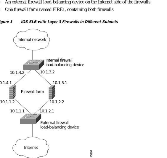
As its name implies, firewall load balancing enables IOS SLB to balance flows to firewalls. Firewall load balancing uses a load-balancing device on each side of a group of firewalls (called a firewall farm) to ensure that the traffic for each flow travels to the same firewall, ensuring that the security policy is not compromised.
You can configure more than one firewall farm in each load-balancing device.
Layer 3 firewalls, which have IP-addressable interfaces, are supported by IOS SLB firewall load balancing if they are subnet-adjacent to the firewall load-balancing device and have unique MAC addresses. The device does not modify the IP addresses in the user packet. To send the packet to the chosen firewall, the device determines which interface to use and changes the Layer 2 headers accordingly. This is the standard dispatched routing used by IOS SLB.
Layer 2 firewalls, which do not have IP addresses, are transparent to IOS SLB firewall load balancing. IOS SLB supports Layer 2 firewalls by placing them between two IP-addressable interfaces.
Whereas many Layer 3 firewalls might exist off a single Layer 3 interface on the load-balancing device (for example, a single LAN), only one Layer 2 firewall can exist off each interface.
When configuring the load-balancing device, you configure a Layer 3 firewall using its IP address, and a Layer 2 firewall using the IP address of the interface of the device on the “other side” of the firewall. To balance flows across the firewalls in a firewall farm, IOS SLB firewall load balancing performs a
route lookup on each incoming flow, examining the source and destination IP addresses (and optionally
the source and destination TCP or User Datagram Protocol [UDP] port numbers). Firewall load balancing applies a hash algorithm to the results of the route lookup and selects the best firewall to handle the connection request.
Note IOS SLB firewall load balancing must examine incoming packets and perform route lookup. On Catalyst 6000 Family Switches, some additional packets might need to be examined. Firewall load balancing impacts internal (secure) side routing performance and must be considered in the complete design.
To maximize availability and resilience in a network with multiple firewalls, configure a separate equal-weight route to each firewall, rather than a single route to only one of the firewalls. IOS SLB firewall load balancing provides the following capabilities:
• Connections initiated from either side of the firewall farm are load-balanced. • The load is balanced among a set of firewalls—the firewall farm.
• All packets for a connection travel through the same firewall. Subsequent connections can be “sticky,” ensuring that they are assigned to the same firewall.
• Probes are used to detect and recover from firewall failures.
• Redundancy is provided. Hot Standby Router Protocol (HSRP), stateless backup, and stateful backup are all supported.
• Multiple interface types and routing protocols are supported, enabling the external (Internet side) load-balancing device to act as an access router.
• Proxy firewalls are supported.
GPRS Load Balancing
General Packet Radio Service (GPRS) is the packet network infrastructure based on the European Telecommunications Standards Institute (ETSI) Global System for Mobile Communication (GSM) phase 2+ standards for transferring packet data from the GSM mobile user to the packet data network (PDN). The Cisco gateway GPRS support node (GGSN) interfaces with the serving GPRS support node (SGSN) using the GPRS Tunneling Protocol (GTP), which in turn uses UDP/IP for transport. IOS SLB provides GPRS load balancing and increased reliability and availability for the GGSN.
Tunnel creation messages destined to the virtual GGSN IP address are redirected via Layer 2 to one of the real GGSNs using the weighted round robin load-balancing algorithm. See the“Weighted Round Robin” section on page 5 for more information about this algorithm.
The real GGSNs must be Layer 2-adjacent to the IOS SLB device. The SGSNs need not be Layer 2-adjacent to the IOS SLB device, unless you implement IOS SLB redundancy enhancements.
GPRS load balancing uses standard dispatched routing, so you must configure the real GGSNs with the virtual GGSN IP address as a loopback address, or secondary IP address. See the“Network Address Translation (NAT) and Session Redirection” section on page 11for more information about dispatched routing. See the “Configuring Logical Interfaces” chapter of the Cisco IOS Interface Configuration
Guide for more information about configuring the loopback address.
When configuring the network shared by IOS SLB and the GGSNs, keep the following considerations in mind:
• Specify static routes (using ip route commands) and real server IP addresses (using real commands) such that the Layer 2 information is correct and unambiguous.
• Do not configure default routes or gateways on any of the GGSNs.
• Do not configure a route to IOS SLB’s virtual server on the GGSNs. Doing so can prevent messages from reaching GTP.
• Choose subnets carefully, using one of the following methods: – Do not overlap virtual template address subnets.
– Specify next hop addresses to real servers, not to interfaces on those servers.
In GPRS load balancing, IOS SLB knows when a PDP context is established, but it does not know when PDP contexts are cleared, and therefore it cannot know the number of open PDP contexts for each GGSN. Use DFP to calculate GPRS load-balancing weights dynamically. See the“Dynamic Feedback Protocol for IOS SLB” section on page 8 for more information about DFP.
If you have enabled Cisco Express Forwarding (CEF) on a GGSN, you must identify the IP address of the GGSN virtual server to CEF. If you have not enabled CEF on the GGSN, do not perform this task. See the“Identifying the GGSN Virtual Server to CEF” section on page 36 for more details.
Maximum Connections
IOS SLB allows you to configure maximum connections for server and firewall load balancing. • For server load balancing, you can configure a limit on the number of active connections that a real
server is assigned. If the maximum number of connections is reached for a real server, IOS SLB automatically switches all further connection requests to another server until the connection number drops below the specified limit.
• For firewall load balancing, you can configure a limit on the number of active TCP or UDP connections that a firewall farm is assigned. If the maximum number of connections is reached for the firewall farm, new connections are dropped until the connection number drops below the specified limit.
Multiple Firewall Farm Support
Network Address Translation (NAT) and Session Redirection
Cisco IOS NAT, RFC 1631, allows unregistered “private” IP addresses to connect to the Internet by translating them into globally registered IP addresses. Cisco IOS NAT also increases network privacy by hiding internal IP addresses from external networks.
IOS SLB can operate in one of two session redirection modes:
• Dispatched mode—the virtual server address is known to the real servers; you must configure the virtual server IP address as a loopback address, or secondary IP address, on each of the real servers. IOS SLB redirects packets to the real servers at the media access control (MAC) layer. Since the virtual server IP address is not modified in dispatched mode, the real servers must be
Layer 2-adjacent to IOS SLB, or intervening routers might not be able to route to the chosen real server.
See the “Configuring Logical Interfaces” chapter of the Cisco IOS Interface Configuration Guide for more information about configuring the loopback address.
• Directed mode—the virtual server can be assigned an IP address that is not known to any of the real servers. IOS SLB translates packets exchanged between a client and real server, translating the virtual server IP address to a real server IP address through NAT.
IOS SLB supports the following types of NAT:
• Server NAT—By replacing the virtual server IP address with the real server IP address (and vice versa):
– Servers can be many hops away from the load-balancing device. – Intervening routers can route to them without requiring tunnelling. – Loopback and secondary interfaces are not required on the real server. – The real server need not be Layer 2-adjacent to IOS SLB.
A less common form of server NAT is server port translation, which involves replacement of a virtual server port. Server port translation does not require server IP address translation, but the two translations can be used together.
Note If an IP address is configured as a real IP address for a NAT virtual server, you cannot balance connection requests from that address to a different virtual server (whether NAT or dispatched) on the same load-balancing device.
• Client NAT—If multiple load-balancing devices are used, replacing the client IP address with an IP address associated with one of the devices results in proper routing of outbound flows to the correct device. Client NAT also requires that the ephemeral client port be modified since many clients can use the same ephemeral port. Even in cases where multiple load-balancing devices are not used, client NAT can be useful to ensure that packets from load-balanced connections are not routed around the device.
In both dispatched and directed modes, IOS SLB must track connections. Therefore, you must design your network so that there is no alternate network path from the real servers to the client that bypasses the load-balancing device.
IOS SLB supports FTP, firewall load balancing, and GPRS load balancing only in dispatched mode. Therefore, FTP, firewall load balancing, and GPRS load balancing cannot use NAT.
Port-Bound Servers
When you define a virtual server, you must specify the TCP or UDP port handled by that virtual server. However, if you configure NAT on the server farm, you can also configure port-bound servers.
Port-bound servers allow one virtual server IP address to represent one set of real servers for one service, such as Hypertext Transfer Protocol (HTTP), and a different set of real servers for another service, such as Telnet.
Packets destined for a virtual server address for a port that is not specified in the virtual server definition are not redirected.
IOS SLB supports both port-bound and non-port-bound servers, but port-bound servers are recommended.
IOS SLB firewall load balancing and GPRS load balancing do not support port-bound servers.
Probes
IOS SLB supports HTTP probes, ping probes, and WSP probes.
HTTP and ping probes are a simple way to verify connectivity for devices being server load-balanced, and for firewalls being firewall load-balanced (even devices on the other side of a firewall).
HTTP probes also enable you to monitor applications being server load-balanced. With frequent probes, the operation of each application is verified, not just connectivity to the application.
HTTP probes do not support HTTP over Secure Socket Layer (HTTPS). That is, you cannot send an HTTP probe to an SSL server.
WSP probes detect failures in the Wireless Application Protocol (WAP) stack on port 9201.
You can configure more than one probe, in any combination of types (HTTP, ping, or WSP), for each server farm, or for each firewall in a firewall farm.
Probes in Server Load Balancing
Probes determine the status of each real server in a server farm. All real servers associated with all virtual servers tied to that server farm are probed.
If a real server fails for one probe, it is failed for all probes. After the real server recovers, all probes must acknowledge its recovery before it is restored to service.
Probes in Firewall Load Balancing
Probes detect firewall failures. All firewalls associated with the firewall farm are probed.
If a firewall fails for one probe, it is failed for all probes. After the firewall recovers, all probes must acknowledge its recovery before it is restored to service.
Make sure you configure the HTTP probe to expect status code 401, to eliminate password problems. See the description of the expect command in the“Command Reference” section on page 91 for more details.
Use the ip http server command to configure an HTTP server on the device. See the description of the ip http server command in the Cisco IOS Configuration Fundamentals Command Reference for more details.
In a transparent webcache load-balancing environment, an HTTP probe uses the real IP address of the webcache, since there is no virtual IP address configured.
Protocol Support
IOS SLB supports the following protocols: • Domain Name System (DNS)
• File Transfer Protocol (FTP) • GPRS Tunneling Protocol (GTP) • Hypertext Transfer Protocol (HTTP)
• Hypertext Transfer Protocol over Secure Socket Layer (HTTPS) • Internet Message Access Protocol (IMAP)
• Mapping of Airline Traffic over IP, Type A (MATIP-A) • Network News Transport Protocol (NNTP)
• Post Office Protocol, version 2 (POP2) • Post Office Protocol, version 3 (POP3) • RealAudio/RealVideo via HTTP
• Remote Authentication Dial-In User Service (RADIUS) • Simple Mail Transport Protocol (SMTP)
• Telnet
• X.25 over TCP (XOT)
Redundancy Enhancements
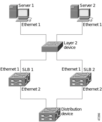
An IOS SLB device can represent a single point of failure, and the servers can lose their connections to the backbone, if either of the following occurs:
• The IOS SLB device fails.
• A link from a switch to the distribution-layer switch becomes disconnected.
To reduce that risk, IOS SLB supports the following redundancy options, based on HSRP: • Stateless Backup, page 14
• Stateful Backup, page 14 • Active Standby, page 14
Stateless Backup
Stateless backup provides high network availability by routing IP flows from hosts on Ethernet networks without relying on the availability of a single Layer 3 switch. Stateless backup is particularly useful for hosts that do not support a router discovery protocol (such as the Intermediate System-to-Intermediate System [IS-IS] Interdomain Routing Protocol [IDRP]) and do not have the functionality to shift to a new Layer 3 switch when their selected Layer 3 switch reloads or loses power.
If you use stateless backup in GPRS load balancing, the SGSNs must be Layer 2-adjacent to the IOS SLB device.
Stateful Backup
Stateful backup enables IOS SLB to incrementally backup its load-balancing decisions, or “keep state,” between primary and backup switches. The backup switch keeps its virtual servers in a dormant state until HSRP detects failover; then the backup (now primary) switch begins advertising virtual addresses and filtering flows. You can use HSRP to configure how quickly the failover is detected.
Stateful backup provides IOS SLB with a one-to-one stateful or idle backup scheme. This means that only one instance of IOS SLB is handling client or server flows at a given time, and that there is at most one backup platform for each active IOS SLB switch.
GPRS load balancing does not support stateful backup.
Active Standby
Active standby enables two IOS SLBs to load-balance the same virtual IP address while at the same time acting as backups for each other. If a site has only one virtual IP address to load balance, an access router is used to direct a subset of the flows to each IOS SLB using policy-based routing.
IOS SLB firewall load balancing does not support active standby. That is, you cannot configure two pairs of firewall load balancing devices (one pair on each side of the firewalls), with each device in each pair handling traffic and backing up its partner.
Route Health Injection
By default, a virtual server’s IP address is advertised (added to the routing table) when you bring the virtual server into service (using the inservice command). If you have a preferred host route to a website's virtual IP address, you can advertise that host route, but you have no guarantee that the IP address is available. However, you can use theadvertisecommand to configure IOS SLB to advertise the host route only when IOS SLB has verified that the IP address is available. IOS SLB withdraws the advertisement when the IP address is no longer available. This function is known as route health
injection.
Note When route health injection is configured, probes require a default route to the virtual server (specified using the ip route 0.0.0.0 0.0.0.0 command, for example). The route is not used, but it must exist to enable the sockets code to verify that the destination can be reached, which in turn is essential for route health injection to function correctly.
Slow Start
In an environment that uses weighted least connections load balancing, a real server that is placed in service initially has no connections, and could therefore be assigned so many new connections that it becomes overloaded. To prevent such an overload, slow start controls the number of new connections that are directed to a real server that has just been placed in service.
GPRS load balancing does not support slow start.
Sticky Connections
When you use sticky connections, new connections from a client IP address or subnet are assigned to the same real server (for server load balancing) or firewall (for firewall load balancing) as were previous connections from that address or subnet.
IOS SLB creates sticky objects to track client assignments. The sticky objects remain in the IOS SLB database after the last sticky connection is deleted, for a user-defined period. New connections from a client are sticky if the following conditions are met:
• The real server is in either OPERATIONAL or MAXCONNS_THROTTLED state. • The sticky timer is defined on a virtual server or on a firewall farm.
• The amount of time between the end of a previous connection from the client and the start of the new connection is within the sticky timer duration.
OR
A connection for the same client already exists. (That is, the connection is not the first for this client.)
Sticky connections allow you to create a sticky object for a subnet, ensuring that all flows from the subnet are sent to the same real server. (Make sure the volume of flows is not so large that it overwhelms the real server.)
Sticky connections also permit the coupling of services that are handled by more than one virtual server or firewall farm. This allows connection requests for related services to use the same real server. For example, web server (HTTP) typically uses TCP port 80, and HTTPS uses port 443. If HTTP virtual servers and HTTPS virtual servers are coupled, connections for ports 80 and 443 from the same client IP address or subnet are assigned to the same real server.
GPRS load balancing does not support sticky connections.
SynGuard
SynGuard limits the rate of TCP start-of-connection packets (SYNchronize sequence numbers, or SYNs) handled by a virtual server to prevent a type of network problem known as a SYN flood denial-of-service
attack. A user might send a large number of SYNs to a server, which could overwhelm or crash the
server, denying service to other users. SynGuard prevents such an attack from bringing down IOS SLB or a real server. SynGuard monitors the number of SYNs handled by a virtual server at specific intervals and does not allow the number to exceed a configured SYN threshold. If the threshold is reached, any new SYNs are dropped.
TCP Session Reassignment
IOS SLB tracks each TCP SYN sent to a real server by a client attempting to open a new connection. If several consecutive SYNs are not answered, or if a SYN is replied to with an RST, the TCP session is reassigned to a new real server. The number of SYN attempts is controlled by a configurable reassign
threshold.
IOS SLB firewall load balancing and GPRS load balancing do not support TCP session reassignment.
Transparent Webcache Load Balancing
IOS SLB can load balance port 80 flows across a cluster of transparent webcaches. To set up this function, configure the subnet IP addresses served by the transparent webcaches, or some common subset of them, as virtual servers. Virtual servers used for transparent webcache load balancing do not answer pings on behalf of the subnet IP addresses, and they do not affect traceroute.
In some cases, such as when its cache does not contain needed pages, a webcache might need to initiate its own connections to the Internet. Those connections should not be load balanced back to the same set of webcaches. To address this need, IOS SLB allows you to configure client exclude statements, which exclude connections initiated by the webcaches from the load-balancing scheme.
IOS SLB firewall load balancing and GPRS load balancing do not support transparent webcache load balancing.
WAP Load Balancing
You can use IOS SLB to load balance Wireless Session Protocol (WSP) sessions among a group of WAP gateways or servers on an IP bearer network. WAP runs on top of UDP on a set of well known ports, with each port indicating a different WAP mode:
• Connectionless WSP mode (IP/UDP [9200]/WSP). In connectionless WSP mode, WSP is a simple one-request/one-response protocol in which a single server-bound packet results in a server response of one or more packets.
• Connection-oriented WSP mode (IP/UDP [9201]/WTP/WSP). In connection-oriented WSP mode, WTP handles retransmissions of WDP events, and WSP operates using a defined session
bring-up/tear-down sequence. IOS SLB uses a WAP-aware finite state machine (FSM), driven by events in WSP sessions, to reassign sessions. This FSM operates only on port 9201, where the WSP sessions are not encrypted and WTP handles retransmissions.
• Connectionless secure WSP mode (IP/UDP [9202]/WTLS/WSP). This mode functions the same as connectionless WSP mode, but with security provided by WTLS.
• Connection-oriented secure WSP mode (IP/UDP [9203]/WTLS/WTP/WSP). This mode functions the same as connection-oriented WSP mode, but with security provided by WTLS.
IOS SLB uses ping probes to detect failures in the WAP load-balancing device, and WSP probes to detect failures in the WAP stack on port 9201.
Benefits
IOS SLB shares the same software code base as Cisco IOS and has all the software features sets of Cisco IOS software. IOS SLB is recommended for customers desiring complete integration of SLB technology into traditional Cisco switches and routers.
On the Cisco Catalyst 6500 switch, IOS SLB takes advantage of hardware acceleration to forward data packets at very high speed when running in dispatched mode.
IOS SLB assures continuous, high availability of content and applications with proven techniques for actively managing servers and connections in a distributed environment. By distributing user requests across a cluster of servers, IOS SLB optimizes responsiveness and system capacity, and dramatically reduces the cost of providing Internet, database, and application services for large-, medium-, and small-scale sites.
IOS SLB facilitates scalability, availability, and ease of maintenance:
• The addition of new physical (real) servers, and the removal or failure of existing servers, can occur at any time, transparently, without affecting the availability of the virtual server.
• IOS SLB's slow start capability allows a new server to increase its load gradually, preventing failures caused by assigning the server too many new connections too quickly.
• IOS SLB supports fragmented packets and packets with IP options, buffering your servers from client or network vagaries that are beyond your control.
• IOS SLB firewall load balancing enables you to scale access to your Internet site. You can add firewalls without affecting existing connections, enabling your site to grow without impacting customers.
Using DFP enables IOS SLB to provide weights to another load-balancing system, such as
DistributedDirector. IOS SLB can act as a DFP manager, receiving weights from host servers, and it can act as a DFP agent, sending weights to a DFP manager. The functions are enabled independently—you can implement either one, or both, at the same time.
Administration of server applications is easier. Clients know only about virtual servers; no administration is required for real server changes.
Security of the real server is provided because its address is never announced to the external network. Users are familiar only with the virtual IP address. You can filter unwanted flows based on both IP address and TCP or UDP port numbers. Additionally, though it does not eliminate the need for a firewall, IOS SLB can help protect against some denial-of-service attacks.
In a branch office, IOS SLB allows balancing of multiple sites and disaster recovery in the event of full-site failure, and distributes the work of load balancing.
Restrictions
IOS SLB has the following restrictions:
• Does not support load balancing of flows between clients and real servers that are on the same local area network (LAN) or virtual LAN (VLAN). The packets being load balanced cannot enter and leave the load-balancing device on the same interface.
• Operates in a standalone mode and currently does not operate as a MultiNode Load Balancing (MNLB) Services Manager. The presence of IOS SLB does not preclude the use of the existing MNLB Forwarding Agent with an external Services Manager (such as the LocalDirector) in an MNLB environment.
• Does not support coordinating server load-balancing statistics among different IOS SLB instances for backup capability.
• Supports FTP, firewall load balancing, and GPRS load balancing only in dispatched mode.
• Does not support IOS SLB and Cisco Applications and Services Architecture (CASA) configured with the same virtual IP address, even if they are for different services.
• Does not support both IOS server load balancing and firewall load balancing on the same flow, nor on the same server port. You can configure both server load balancing and firewall load balancing on the same device at the same time, but they must apply to different flows (different client-server pairs). These functions can run on the same EPIF (for example, server load balancing on port 1 and firewall load balancing on port 2). Load-balancing the server farm after a packet exits the
load-balanced firewall farm requires a separate load-balancing device.
• Does not support running both IOS SLB and the Content Switching Module (CSM) on the same switch.
• When operating in dispatched mode, real servers must be Layer 2-adjacent, tag-switched, or via generic routing encapsulation (GRE) tunnel.
• When operating in directed mode with server NAT, real servers need not be Layer 2-adjacent to IOS SLB. This allows for more flexible network design, since servers can be placed several Layer 3 hops away from the IOS SLB switch.
• The DFP agent requires a delay between hello messages of at least 3 seconds. Therefore, if your DFP manager provides a timeout specification, you must set the timeout to at least 3 seconds. • For backup server farm support:
– Does not support defining the same real server in both primary and backup server farms. – Requires the same NAT configuration (none, client, server, or both) for both primary and backup
server farms. In addition, if NAT is specified, both server farms must use the same NAT pool. – Does not support HTTP redirect load balancing. If a primary server farm specifies a redirect
virtual server, you cannot define that primary as a backup, nor can you define a backup for that primary.
• For firewall load balancing:
– No longer limited to a single firewall farm in each load-balancing device.
– Limited to a single active firewall load-balancing device on each side of the firewall farm. Each firewall must have its own unique MAC address and must be Layer 2-adjacent to each device. The firewalls can be connected to individual interfaces on the device, or they can all share a VLAN and connect using a single interface.
– Requires Ethernet between each firewall load-balancing device and each firewall.
– On each firewall load-balancing device, requires that each Layer 2 firewall be connected to a single Layer 3 (IP) interface.
– Flows with a destination IP address on the same subnet as the configured firewall IP addresses are not load-balanced. (Such flows could be a firewall console session or other flows on the firewall LAN.)
– Does not support the following IOS SLB functions: - Active standby
- Network Address Translation (NAT) - Port-bound servers
- TCP session reassignment
- Transparent webcache load balancing • For GPRS load balancing:
– Operates in dispatched mode only.
– Cannot load balance network-initiated PDP context requests. – Does not support the following IOS SLB functions:
- Bind IDs
- Client-assigned load balancing - Network Address Translation (NAT) - Port-bound servers - Slow Start - Stateful backup - Sticky connections - SynGuard - TCP session reassignment
- Transparent webcache load balancing
- Weighted least connections load-balancing algorithm. GPRS load balancing requires the weighted round robin algorithm. A server farm that uses weighted least connections can be bound to a virtual server providing GPRS load balancing, but you cannot place the virtual server INSERVICE. If you try to do so, IOS SLB issues an error message.
• For HTTP probes:
– HTTP probes do not support HTTP over Secure Socket Layer (HTTPS). That is, you cannot send an HTTP probe to an SSL server.
• For Catalyst 6000 Family Switches:
– Requires the Multilayer Switched Feature Card (MSFC) and the Policy Feature Card (PFC). When using redundant MSFCs in the same Catalyst 6000 Family switch, stateful backup between the two MSFCs is not supported, but stateless backup between the two MSFCs is supported.
The term “MSFC” refers to either an MSFC1 or an MSFC2, except when specifically differentiated.
The term “PFC” refers to either a PFC1 or a PFC2, except when specifically differentiated. – Requires that the Multilayer Switching (MLS) flow mode be set to full. For more information
about how to set the MLS flow, refer to the “Configuring IP Multilayer Switching” section in the Catalyst 6000 Family MSFC (12.0) & PFC Configuration Guide, Release 5.4.
– When operating in dispatched mode, real servers must be Layer 2-adjacent to IOS SLB (that is, not beyond an additional router), with hardware data packet acceleration performed by the PFC. All real servers that can be reached by a single IOS SLB device (that is, all real servers in a given server farm) be on the same VLAN. The loopback address must be configured in the real servers.
– Provides no hardware data packet acceleration in directed mode. (Hardware data packet acceleration is performed by the PFC, and in directed mode the data packets are handled by the MSFC, not the PFC.)
– Supports Native IOS only.
– Does not support GPRS load balancing in 12.1(9)E. • For the Cisco 7100 Series and Cisco 7200 Series:
– Provides no hardware acceleration for the IOS SLB function for either dispatched mode or directed mode.
– Supports Cisco IOS NAT in directed mode with no hardware data packet acceleration. – Does not support route health injection in 12.1(9)E.
Related Features and Technologies
• Content Flow Monitor (CFM)• Dynamic Feedback Protocol (DFP) • General Packet Radio Service (GPRS) • Hot Standby Router Protocol (HSRP) • Network Address Translation (NAT) • Wireless Application Protocol (WAP)
Related Documents
• Catalyst 4840G Software Feature and Configuration Guide
• Cisco IOS IP Configuration Guide
• Cisco IOS IP Command Reference, Volume 1 of 3: Addressing and Services, Release 12.2
• Cisco IOS Mobile Wireless Configuration Guide
• Cisco IOS Mobile Wireless Command Reference
• Dynamic Feedback Protocol Support in Distributed Director
• Using Content Flow Monitor
Supported Platforms
• Catalyst 6000 Family Switches with Supervisor Engine 1 • Catalyst 6000 Family Switches with Supervisor Engine 2 • Cisco 7100 Series Routers
Supported Standards, MIBs, and RFCs
Standards• No new or modified standards
MIBs
• CISCO-SLB-MIB
Note Although the objects in this MIB are defined as read-create, you cannot use the SNMP SET command to modify them. Instead, you must use the command line to set the associated command line keywords, after which the new values are reflected in SNMP.
RFCs
• Cisco IOS NAT, RFC 1631
Configuration Tasks
Configuring IOS SLB involves identifying server farms, configuring groups of real servers in server farms, and configuring the virtual servers that represent the real servers to the clients.
For configuration examples associated with these tasks, see the“Configuration Examples” section on page 41.
For a complete description of the IOS SLB commands in this section, see the“Command Reference” section on page 91. To locate documentation of other commands that appear in this section, search online using Cisco.com.
To configure IOS SLB, perform the tasks in the following sections:
• Configuring Required and Optional IOS SLB Functions, page 22 (Required) • Configuring Firewall Load Balancing, page 28 (Optional)
• Configuring Probes, page 32 (Optional) • Configuring DFP, page 34 (Optional)
• GPRS Load Balancing Configuration Task List, page 34 (Optional) • Configuring NAT, page 36 (Optional)
• Stateless Backup Configuration Task List, page 37 (Optional) • Configuring Database Entries, page 38 (Optional)
• Configuring Wildcard Searches, page 38 (Optional) • Clearing Connections and Counters, page 39 (Optional) • Purging Connections, page 39 (Optional)
Configuring Required and Optional IOS SLB Functions
To configure IOS SLB functions, perform the tasks in the following sections. Required and optional tasks are indicated.
• Configuring a Server Farm and Real Server, page 22 (Required) • Configuring a Virtual Server, page 25 (Required)
• Verifying the Server Farm, page 27 (Optional) • Verifying the Virtual Server, page 27 (Optional) • Verifying the Clients, page 27 (Optional)
• Verifying IOS SLB Connectivity, page 28 (Optional)
Configuring a Server Farm and Real Server
To configure an IOS SLB server farm, use the following commands beginning in global configuration mode:
Command Purpose
Step 1 Router(config)# ip slb serverfarm serverfarm-name Router(config-slb-sfarm)#
Adds a server farm definition to the IOS SLB configuration and enters server farm configuration mode.
Step 2 Router(config-slb-sfarm)# bindid [bind_id] (Optional) Specifies a bind ID on the server farm for
use by DFP.
Note GPRS load balancing does not support this command.
Step 3 Router(config-slb-sfarm)# nat {client pool-name |
server}
(Optional) Configures NAT client translation mode or NAT server address translation mode on the server farm.
Note GPRS load balancing does not support this command.
Step 4 Router(config-slb-sfarm)# predictor [roundrobin |
leastconns]
(Optional) Specifies the algorithm to be used to determine how a real server is selected.
Note GPRS load balancing requires the weighted round robin algorithm, which is the default setting.
See the following sections for more details about each algorithm:
• Weighted Round Robin, page 5 • Weighted Least Connections, page 5
Step 5 Router(config-slb-sfarm)# probe name (Optional) Associates a probe with the real server.
Step 6 Router(config-slb-sfarm)# real ip-address [port_number]
Identifies a real server by IP address and optional port number as a member of a server farm and enters real server configuration mode.
Note In GPRS load balancing, specify the IP addresses (virtual template addresses) of the real servers performing the GGSN function.
Step 7 Router(config-slb-real)# faildetect numconns number-conns [numclients number-clients]
(Optional) Specifies the number of consecutive connection failures and, optionally, the number of unique client connection failures, that constitute failure of the real server.
In GPRS load balancing, if there is only one SGSN in your environment, specify the numclients keyword with a value of 1.
Step 8 Router(config-slb-real)# maxconns number-conns (Optional) Specifies the maximum number of active
connections allowed on the real server at one time.
Note GPRS load balancing requires a maxconns value of 4294967295, which is the default value. The impact of this command in GPRS load balancing is minimal because sessions are very short-lived.
Note When performing server load balancing and firewall load balancing together on a Catalyst 6000 Family Switch, use the mls ip slb wildcard search rp command to reduce the probability of exceeding the capacity of the TCAM on the PFC. See the“Configuring Wildcard Searches” section on page 38for more details.
Step 9 Router(config-slb-real)# reassign threshold (Optional) Specifies the threshold of consecutive
unacknowledged synchronizations or Create PDP requests that, if exceeded, result in an attempted connection to a different real server.
Note In GPRS load balancing, you must specify a reassign threshold less than the value specified on the gprs gtp n3-requests command (or the equivalent command, if you are not using a Cisco SGSN).
Step 10 Router(config-slb-real)# retry retry-value (Optional) Specifies the interval, in seconds, to wait
between the detection of a server failure and the next attempt to connect to the failed server.
Step 11 Router(config-slb-real)# weight weighting-value (Optional) Specifies the real server’s workload
capacity relative to other servers in the server farm.
Note If you use DFP, the static weights you define using the weight (server farm) command are overridden by the weights calculated by DFP. If DFP is removed from the network, IOS SLB reverts to the static weights.
Step 12 Router(config-slb-real)# inservice Enables the real server for use by IOS SLB.
Configuring a Virtual Server
To configure an IOS SLB virtual server, use the following commands beginning in global configuration mode:
Command Purpose
Step 1 Router(config)# ip slb vserver virtual_server-name Identifies a virtual server and enters virtual server
configuration mode. Step 2 Router(config-slb-vserver)# virtual ip-address
[network-mask] {tcp | udp} [port-number | wsp |
wsp-wtp | wsp-wtls | wsp-wtp-wtls] [service
service-name]
Specifies the virtual server IP address, type of connection, TCP or UDP port number, WSP mode, and optional service coupling.
Note In GPRS load balancing, you must specify a virtual GGSN IP address as the virtual server, and use the udp and service gtp keyword options. Port number 3386 is recommended, if the GGSNs and SGSNs are in compliance with the ETSI standard.
Step 3 Router(config-slb-vserver)# serverfarm primary-serverfarm-name [backup
backup-serverfarm-name [sticky]]
Associates a real server farm with a virtual server, or configures a backup server farm.
Note GPRS load balancing does not support the sticky attribute.
Step 4 Router(config-slb-vserver)# advertise (Optional) Controls the installation of a static route
to the Null0 interface for a virtual server address. Step 5 Router(config-slb-vserver)# client ip-address
network-mask
(Optional) Specifies which clients are allowed to use the virtual server.
Note GPRS load balancing does not support this command.
Step 6 Router(config-slb-vserver)# delay duration (Optional) Specifies the amount of time IOS SLB
maintains TCP connection context after a connection has terminated.
Step 7 Router(config-slb-vserver)# idle duration (Optional) Specifies the minimum amount of time
IOS SLB maintains connection context in the absence of packet activity.
Note In GPRS load balancing, you must specify an idle timer greater than the longest possible longest possible interval between PDP context requests on the SGSN. Also, the default is 30 seconds in GPRS load balancing, but 3600 seconds (1 hour) in all other environments.
Step 8 Router(config-slb-vserver)# replicate casa listening-ip remote-ip port-number [interval]
[password [0|7] password timeout]
(Optional) Configures a stateful backup of IOS SLB decision tables to a backup switch.
Note GPRS load balancing does not support this command.
Step 9 Router(config-slb-vserver)# sticky duration [group group-id] [netmask netmask]
(Optional) Specifies that connections from the same client use the same real server, as long as the interval between client connections does not exceed the specified duration.
Note GPRS load balancing does not support this command.
Step 10 Router(config-slb-vserver)# synguard syn-count interval
(Optional) Specifies the rate of TCP SYNs handled by a virtual server in order to prevent a SYN flood denial-of-service attack.
Note GPRS load balancing does not support this command.
Step 11 Router(config-slb-vserver)# inservice Enables the virtual server for use by IOS SLB.
Step 12 Router(config-slb-vserver)# client ip-address network-mask
Specifies which clients are allowed to use the virtual server.
Verifying the Virtual Server
The following show ip slb vserver command verifies the configuration of the virtual servers PUBLIC_HTTP and RESTRICTED_HTTP:
Router# show ip slb vserver
slb vserver prot virtual state conns
---PUBLIC_HTTP TCP 10.0.0.1:80 OPERATIONAL 0
RESTRICTED_HTTP TCP 10.0.0.2:80 OPERATIONAL 0
Router#
Verifying the Server Farm
The following show ip slb reals command displays the status of server farms PUBLIC and RESTRICTED, the associated real servers, and their status:
Router# show ip slb real
real farm name weight state conns ---10.1.1.1 PUBLIC 8 OPERATIONAL 0 10.1.1.2 PUBLIC 8 OPERATIONAL 0 10.1.1.3 PUBLIC 8 OPERATIONAL 0 10.1.1.20 RESTRICTED 8 OPERATIONAL 0 10.1.1.21 RESTRICTED 8 OPERATIONAL 0 Router#
The following show ip slb serverfarm command displays the configuration and status of server farms PUBLIC and RESTRICTED:
Router# show ip slb serverfarm
server farm predictor nat reals bind id
---PUBLIC ROUNDROBIN none 3 0
RESTRICTED ROUNDROBIN none 2 0
Router#
Verifying the Clients
The following show ip slb conns command verifies the restricted client access and status:
Router# show ip slb conns
vserver prot client real state nat
---RESTRICTED_HTTP TCP 10.4.4.0:80 10.1.1.20 CLOSING none
Router#
The following show ip slb conns command displays detailed information about the restricted client access status:
Router# show ip slb conns client 10.4.4.0 detail VSTEST_UDP, client = 10.4.4.0:80
state = CLOSING, real = 10.1.1.20, nat = none v_ip = 10.0.0.2:80, TCP, service = NONE
client_syns = 0, sticky = FALSE, flows attached = 0 Router#
Verifying IOS SLB Connectivity
To verify that the IOS SLB feature has been installed and is operating correctly, ping the real servers from the IOS SLB switch, then ping the virtual servers from the clients.
The following show ip slb stats command displays detailed information about the IOS SLB network status:
Router# show ip slb stats
Pkts via normal switching: 0
Pkts via special switching: 6 Connections Created: 1 Connections Established: 1 Connections Destroyed: 0 Connections Reassigned: 0 Zombie Count: 0 Connections Reused: 0
Normal switching is when IOS SLB packets are handled on normal IOS switching paths (CEF, fastswitching, and process level switching). Special switching is when IOS SLB packets are handled on hardware-assisted switching paths.
See the“Monitoring and Maintaining the IOS SLB Feature” section on page 40for additional commands used to verify IOS SLB networks and connections.
Configuring Firewall Load Balancing
This section describes the tasks required to configure a basic IOS SLB firewall load-balancing network. IOS SLB firewall load balancing uses probes to detect and recover from failures. You must configure a probe on each real server in the firewall farm. Ping probes are recommended; see the“Configuring Ping Probes” section on page 33for more details. If a firewall does not allow ping probes to be forwarded, use HTTP probes instead. See the“Configuring HTTP Probes” section on page 32 for more details. You can configure more than one probe, in any combination of types (HTTP or ping), for each firewall in a firewall farm.
When performing server load balancing and firewall load balancing together on a Catalyst 6000 Family Switch, use the mls ip slb wildcard search rp command to reduce the probability of exceeding the capacity of the TCAM on the PFC. See the“Configuring Wildcard Searches” section on page 38for more details.
This section describes the following IOS SLB firewall load-balancing configuration tasks. Required and optional tasks are indicated.
• Configuring the Firewall Farm, page 29 (Required) • Verifying the Firewall Farm, page 30 (Optional) • Verifying Firewall Connectivity, page 31 (Optional)
Configuring the Firewall Farm
To configure an IOS SLB firewall load-balancing network, enter the following commands in order, beginning in global configuration mode:
Command Purpose
Step 1 Router(config)# ip slb firewallfarm firewallfarm-name
Router(config-slb-fw)#
Adds a firewall farm definition to the IOS SLB configuration and enters firewall farm configuration mode.
Step 2 Router(config-slb-fw)# real ip-address Identifies a firewall by IP address as a member of a
firewall farm and enters real server configuration mode.
Step 3 Router(config-slb-fw-real)# probe name Associates a probe with the firewall.
Step 4 Router(config-slb-fw-real)# weight weighting-value (Optional) Specifies the firewall’s workload
capacity relative to other firewalls in the firewall farm.
Step 5 Router(config-slb-fw-real)# inservice Enables the firewall for use by the firewall farm and
by IOS SLB. Step 6 Router(config-slb-fw)# access [source
source-ip-address network-mask] [destination destination-ip-address network-mask]
(Optional) Routes specific flows to a firewall farm.
Step 7 Router(config-slb-fw)# predictor hash address [port] (Optional) Specifies whether the source and
destination TCP or UDP port numbers, in addition to the source and destination IP addresses, are to be used when selecting a firewall.
Step 8 Router(config-slb-fw)# replicate casa listening-ip remote-ip port-number [interval] [password [0|7] password [timeout]]
(Optional) Configures a stateful backup of IOS SLB firewall load balancing decision tables to a backup switch.
Step 9 Router(config-slb-fw)# tcp (Optional) Enters TCP protocol configuration mode.
Step 10 Router(config-slb-fw-tcp)# delay duration (Optional) For firewall farm TCP protocol
configuration mode, specifies the amount of time IOS SLB firewall load balancing maintains TCP connection context after a connection has terminated.
Step 11 Router(config-slb-fw-tcp)# idle duration (Optional) For firewall farm TCP protocol
configuration mode, specifies the minimum amount of time IOS SLB firewall load balancing maintains connection context in the absence of packet activity. Step 12 Router(config-slb-fw-tcp)# maxconns number-conns (Optional) For firewall farm TCP protocol
configuration mode, specifies the maximum number of active connections allowed on the firewall farm at one time.
Verifying the Firewall Farm
The following show ip slb reals command displays the status of firewall farm FIRE1, the associated real servers, and their status:
Router# show ip slb real
real farm name weight state conns ---10.1.1.2 FIRE1 8 OPERATIONAL 0 10.1.2.2 FIRE1 8 OPERATIONAL 0
The following show ip slb firewallfarm command displays the configuration and status of firewall farm FIRE1:
Router# show ip slb firewallfarm
firewall farm hash state reals ---FIRE1 IPADDR INSERVICE 2
Step 13 Router(config-slb-fw-tcp)# sticky duration [netmask netmask]
(Optional) For firewall farm TCP protocol
configuration mode, specifies that connections from the same IP address use the same firewall if either of the following conditions is met:
• As long as any connection from that IP address exists.
• For a period, defined by duration, after the last connection is destroyed.
Step 14 Router(config-slb-fw)# udp (Optional) Enters UDP protocol configuration
mode.
Step 15 Router(config-slb-fw-udp)# idle duration (Optional) For firewall farm UDP protocol
configuration mode, specifies the minimum amount of time IOS SLB firewall load balancing maintains connection context in the absence of packet activity. Step 16 Router(config-slb-fw-udp)# maxconns number-conns (Optional) For firewall farm UDP protocol
configuration mode, specifies the maximum number of active connections allowed on the firewall farm at one time.
Step 17 Router(config-slb-fw-udp)# sticky duration [netmask netmask]
(Optional) For firewall farm UDP protocol
configuration mode, specifies that connections from the same IP address use the same firewall if either of the following conditions is met:
• As long as any connection from that IP address exists.
• For a period, defined by duration, after the last connection is destroyed.
Step 18 Router(config-slb-fw)# inservice Enables the firewall farm for use by IOS SLB.
Verifying Firewall Connectivity
To verify that IOS SLB firewall load balancing has been configured and is operating correctly: Step 1 Ping the external real servers (the ones outside the firewall) from the IOS SLB firewall load-balancing
switch.
Step 2 Ping the internal real servers (the ones inside the firewall) from the clients.
Step 3 Use the show ip slb stats command to display detailed information about the IOS SLB firewall load-balancing network status:
Router# show ip slb stats
Pkts via normal switching: 0
Pkts via special switching: 0 Connections Created: 1911871 Connections Established: 1967754 Connections Destroyed: 1313251 Connections Reassigned: 0 Zombie Count: 0 Connections Reused: 59752 Connection Flowcache Purges:1776582 Failed Connection Allocs: 17945 Failed Real Assignments: 0
Normal switching is when IOS SLB packets are handled on normal IOS switching paths (CEF, fastswitching, and process level switching). Special switching is when IOS SLB packets are handled on hardware-assisted switching paths.
Step 4 Use the show ip slb real detail command to display detailed information about the IOS SLB firewall load-balancing real server status:
Router# show ip slb real detail
10.1.1.3, FIRE1, state = OPERATIONAL, type = firewall conns = 299310, dummy_conns = 0, maxconns = 4294967295 weight = 10, weight(admin) = 10, metric = 104, remainder = 2 total conns established = 1074779, hash count = 4646
server failures = 0
interface FastEthernet1/0, MAC 0010.f68f.7020
Step 5 Use the show ip slb conns command to display detailed information about the active IOS SLB firewall load-balancing connections:
Router# show ip slb conns
vserver prot client real state nat
---FirewallTCP TCP 80.80.50.187:40000 10.1.1.4 ESTAB none
FirewallTCP TCP 80.80.50.187:40000 10.1.1.4 ESTAB none
FirewallTCP TCP 80.80.50.187:40000 10.1.1.4 ESTAB none
FirewallTCP TCP 80.80.50.187:40000 10.1.1.4 ESTAB none
FirewallTCP TCP 80.80.50.187:40000 10.1.1.4 ESTAB none
Step 6 See the“Monitoring and Maintaining the IOS SLB Feature” section on page 40for additional commands used to verify IOS SLB networks and connections.