1
3. Transmission System
What is Transmission?
The transmission is a device that is connected to the back of the engine and sends the power from the engine to the drive wheels. Purpose of the transmission is to provide high torque at the time of starting the engine, hill climbing, accelerating and pulling a road
.
Necessity of gear box in Automobiles
:The purpose of transmission is to provide high torque at the time of starting, hill climbing, accelerating and pulling a load. The vehicle will have to face the resistances like wind resistance, gradient resistance and rolling resistance. The tractive effort of the vehicle can be available at various speeds.
The variation of total resistance to the vehicle motion is equal to the tractive effort of the vehicle with speed.
Functions of Transmissions
The main functions which are performed by the transmissions are:
1. The torque produced by engine varies with speed only with narrow limits. But under practical considerations running of automobile demands a large variation of torque available at the road wheels. Hence the main purpose of the transmission is to provide a means to vary the torque ratio between the engine and the road wheels as required.
2. The transmission also provides a neutral position so that the engine and the road wheels are disconnected even when the clutch is in engaged position.
3. A means to back the car by reversing the direction of rotation of the drive is also provided by transmission.
Requirements of Gearboxes
1) To fix the required speed to the vehicle. 2) To vary the speed of the output shaft.
3) To provide high torque when climbing hills and when starting.
4) It would be more preferable to have just the wheel alone turning at high speed. 5) It serves to reserve the vehicle since engine can run in one direction.
2
Types of Gearboxes
I) Selective Gear Transmission 1) Sliding Mesh type 2) Constant Mesh type 3) Synchromesh type
i) Three speed gear box ii) Four speed gear box iii) Six speed gear box II) Planetary gear transmission
1) Epicyclic gear type 2) Automatic Transmission III) Twin top type gear box
IV) Pre-selective gear box
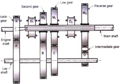
Sliding mesh gearbox
3
It is the simplest type of gear box. Above Fig gives a simplified view of the gear box. The
clutch gear is rigidly fixed to the clutch shaft. It remains always connected to the drive gear of the lay shaft (counter shaft). The other gears also rigidly fixed to the counter shaft. A reverse idler gear is mounted on another shaft and always remains connected to the reverse gear of the counter shaft. The power is transmitted from the engine to the clutch shaft of gear box and will be transmitted to the main shaft through counter shaft. The required speed is obtained by shifting the gears in counter shaft by selective mechanism.
The power comes from the engine to the clutch shaft and thence to the clutch gear which is always in mesh with a gear on the lay shaft. All the gears on the lay shaft are fixed to it and as such they are all the time rotating when the engine is running and the clutch is engaged. Three direct and one reverse speeds are attained on suitably moving the gear on the main shaft by means of selector mechanism.
*Gear pairs as follows
Low gear: - A-B-C-D Top gear: - A-F
Reverse gear: - A-B-G-D
Advantages:-
1) Wear of dog teeth during engaging and disengaging is decreases because all the teeth of dog clutches are involved.
2) Helical gears have high torque transmission capacity.
Constant Mesh Gearbox
In this type of gear box, all the gears of main shaft are in constant mesh with the corresponding gears on the lay shaft. Two dog clutches are provided to the main shaft one between the clutch gear and second gear and the other between the first and reverse gears. The dog clutches are provided which are free to slide on the main shaft
4
Fig: Constant mesh gearbox
When the left dog clutch is slide to the left by means of selector mechanism, its teeth are engaged with those on the gear and then the top gear enclosed. However when slide to right makes contact with the second gear and second gear is obtained.
Double de – clutching:
In constant mesh gear box, for smooth engagement of dog clutches it is necessary that the speed of main shaft and sliding dog clutch must be equal. To obtain lower gear, the speeds of the clutch shaft, lay shaft and main shaft must be increased. This is done by double declutching. The clutch is disengaged and the gear is brought to neutral. Then the clutch is engaged and accelerator pedal pressed to increase the speed of the main shaft gears. Again the clutch is disengaged and the gear moved to the required lower gear and the clutch is again engaged. As the clutch is disengaged twice, it is called double declutching.
*Gear pairs as follows
• Low gear:-K-A-B-C-M1- dog D2 main shaft for final drive
• Second gear:-K-A-B-M2-dog D1 main shaft for final drive
• Top gear:-K-dogD1 main shaft for final drive
5
SYNCHROMESH GEARBOX:
Fig: - Synchromesh Gearbox
In modern cars, helical gears and synchromesh devices are used in gear boxes to synchronize the rotation of gears that are about to be meshed. This gear box is provided with synchromesh devices by which two gears to be engaged are first brought into frictional contact which they are engaged smoothly.
When the gear lever is moved, the synchronizer cone meets with a similar cone on the pinion. Due to the friction, the rotating pinion is made to rotate at the same speed as the synchromesh unit.
To give a positive drive further movement of the gear lever enables the coupling to override several spring loaded balls and the coupling engages with the dog on the ride of the pinion. Since both pinion and synchromesh unit are moving at the same speed, this engagement is done without noise or damage to the dogs.
Constructional details of gear box:
The gear box consists of the following main parts 1. Gear box housing
2. Primary shaft (or) Clutch shaft 3. Lay Shaft (or) Counter shaft 4. Main shaft
5. Selector Mechanism 6. Reverse gear.
6 Gear box housing is used to house all the gear shafts along with gears. The Lubricating oil is poured in the housing to lubricate the gears and shafts. Primary Shaft is the main drive gear which is connected to the clutch at its front end. Its rear end is having gear teeth and is connected to the counter shaft. Counter Shaft is another Shaft having gears of different speeds which will connect to the corresponding gears in main shaft by means of selecting forks in the selector mechanism. Main Shaft is also having gears of different speeds. From this shaft only the transmission will be done to the propeller shaft through universal joint.
Selector Mechanism: It consists of gear lever, gear box top cover, spring leaded balls, selector
sleeves and selector forks.
Reverse gear: The reverse gear is housed in the gear box separately. When selected only, it also will
be engaged with the same speed as the First gear.
*Gear Pairs:-
Low gear:-B-U1-U3-D-R2-R1 Second gear: - B-U1-U2-C-M2-M1 Third gear: - B-U1-U2-D-R2-R1 Top gear: - B-U1-M2-M1
Reverse gear: - B-U1-U4-U5-E-R2-R1
Overdrive
Fig: - Overdrive
Overdrive is a device interposed between the transmission and propeller shaft to permit the propeller shaft to turn faster than, or overdrive, the transmission ratio shaft. It is so called because it provides a speed ratio over that of the high speed radio. The overdrive permits the engine to operate only about 70% of the propeller shaft speed. When the vehicle is operating in the high speed ranges, which in turn extends the engine life, improve the fuel consumption and reduces vibration and noises. The overdrive is essentially suited to high powered cars employing three-speed gear boxes,
7 since in order to produce flexible top gear performance a low gear final drive may be necessary, resulting in the engine running faster at high speeds than is desired.
Generally an overdrive is fitted to the top gear only, but some sports cars have an overdrive on second, third and top gear, giving seven forward speeds. Overdrive is usually employed to supplement conventional transmission. It is bolted to the rear of the transmission between the transmission and the propeller shaft a slightly higher rear-axle gear ratio is employed with an overdrive than without one.
The overdrive includes two essential devices, a freewheeling mechanism and a planetary gear set these are also explained in the following articles.
Overdrive Construction:
It consists of the following parts 1. A set of planetary gear2. A solenoid and planetary gear arrangement for locking the sun gear
3. A rail and fork assembly linked to dash control knob for disconnecting the overdrive when not in use.
4. A free wheel assembly or over running clutch that drives the main shaft below the cut in speed. The planetary gears are used to increase speed by arranging to have the ring gear driven by the planet-pinion cage when the sun gear is locked. Because the increase in speed of the main shaft decreases the power available to drive the wheels, the overdrive ratio can be used only when the engine is running fast enough to develop enough torque to offset this handicap. The maximum speed at which the engine can do this is called cut in speed. Below this speed, the drive is made direct by unlocking the sun gear. The ring gear is splined to the outer case of the freewheel assembly, which is a part of the overdrive main shaft. When the pawl is not engaged in the gear plate, the sun gear is unlocked and the planetary gears cannot transmit power. Then the unit is in direct drive. In this case, the power flows from transmission main shaft to the freewheel assembly and then to the overdrive main shaft.
8 In this system there is no requirement of clutch pressure and changing the gear. Automatic transmission clutch works automatically. This system is generally also called hydrometric transmission. It contains epicyclic gear arrangement, fluid coupling and torque converter. In these planetary gears sets are placed in series to provide transmission. In this centrifugal governor is fitted in transmissions which selects the proper gear speed and throttle position. This system contains hydraulic pistons accomplished with spring control brake bonds on the planetary gear sets and clutches within the planetary gear base arrangement.
Neutral ® Drive ® Low ® Reverse.
In this neutral show that engine is disconnected with transmission system, Drive shows when vehicle move straight on road, low shows when vehicle moves on hilly roads or middy area and reverse position shows when vehicle required reversed motion.
Automatic transmission system has following advantages. 1. It simplified driving control.
2. Noiseless gear shifting.
3. Smoother running due to hydraulic coupling. 4. Longer life than mechanical gears.
5. Less fatigue to drives or less stress while driving.
6. without clutch, pedal and complicated lever changing mechanism.
DIFFERENCIAL UNIT:-
It is the mechanism by which outer wheel runs faster than inner wheel, while moving on curved road. It consist of number of gear (crown wheel, drive Pinion, star pinion sun gear and pin)
9 when power is provided by drive pinion which rotates the sun gears. Sun gear is located parallel to ring gear inside the differential chamber and they are face together. When vehicle is moving there is some resistance both the driving wheels. And offered to the axle shaft more at same speed. But at turn this thing never happens. When vehicle turns to particular side the binding force act on the inner wheel being closer to the point around which wheel moves, the sun gear of that side rotate slow as compared to outer wheel which causes faster speed of outer wheel.
Necessity of Differential:
When the vehicle is taking a turn, the outer wheels will have to travel greater distance as compared to the inner wheels in the same time. If therefore, the vehicle has as a solid rear axle only, there will be tendency for the wheels to skid. Hence if the wheel skidding is to be avoided, some mechanism should be provided in the drive axle.
The Mechanism which reduces the speed of inner wheels and increases the speed of outer wheels when taking turn and while running straight it keeps the speeds of all the wheels same in known as differential mechanism.
Construction and working of Differential: The following are the main parts of differential. 1. Differential Housing
2. Crown wheel (or) Crown pinion 3. Sun pinions or sun gears
4. Star pinions or star gears 5. Axle Half shafts
6. Final drive.
The Sun gears are mounted on the inner end of each half shaft of the drive axle. The Crown wheel is attached in the differential cage to which the power is transmitted from gear box through propeller shaft and final drive bevel pinion. When the differential unit rotates, both the sun gears rotate and thus both wheels turn which are attached to the half shafts. Suppose one wheel is held stationary, the gears of star pinions carry rotary motion to the outer axle causing it to rotate.
Therefore, when one rear wheel runs more rapidly than the other, While the car taking a turn, the star gears spin on the shaft transmitting more rotary motion to the outer wheel. This causes faster rotating of outer wheel than the inner.
1. Differential Lock:
The torque transmitted by the bevel gear differential to each of the rear wheels remains equal even when they are rotating at different speeds. Due to this reason if one wheel in on a slippery surface, mend, lose dirt or sand the wheel on the solid ground will not be driven while the other spins around idly. When the differential lock is applied, the differential action is stopped and the
10 whole torque is then applied to the wheel which is gripping on the road.
2. Self Locking Differential:
A self locking differential consists of two clutches, one on each side, to lock the side gears and axles to the differential cage, when the differential action is not desired. The mechanism consists of four differential pinion gears mounted on two cross shafts at right angles to each other.
When the differential cage is driven by the rear axle gears, the turning resistance causes the cross shafts to move up the ramps and push the shafts apart. This action forces the pinions on each shaft to bear against the side gear rings in order to apply the clutch which locks both axle shafts and force them to turn at the same speed.
UNIVERSAL JOINTS:
Universal joints are used to connect two shafts at an angle to transmit torque. The main shaft of transmission, propeller shaft and differential are not in one line and hence the connection between them is made by universal joints.
TYPES OF UNIVERSAL JOINTS:
The Universal joints are classified into different types. Some of them are a) Cross type (or) Spender and two yoke
b) Ball and trunion type c) Constant Velocity type
a) Cross type Universal Joint consists of cross piece or spider and two yokes. There are four needle
bearings, one for each trunion of the spider.
b) The Ball and Trunion type Universal joint consists of a ball head fastened to the end of the
propeller shaft through which a pin is pressed.
c) The constant velocity Universal joint consists of two individual Universal Joints linked by Ball
and socket. The Ball and sockets split the end of two propeller shafts between the two Universal joints. This type of joint permits uniform motion.
11
Slip joint: Slip joint is used to adjust the length of the propeller shaft as and when demanded by the
rear axle movements.
When the rear spring compresses, the differential rises up and the propeller shaft is shortened. When the springs again expand, the differential returns to its original position and the propeller shaft gets its original length. Therefore a slip joint or sliding joint is used to compensate for the change in length of the propeller shaft.
Torque Converter
Fig:-Torque Converter
On automatic transmissions, the torque converter takes the place of the clutch found on standard shift vehicles. It is there to allow the engine to continue running when the vehicle comes to a stop. The principle behind a torque converter is like taking a fan that is plugged into the wall and blowing air into another fan which is unplugged. If you grab the blade on the unplugged fan, you are able to hold it from turning but as soon as you let go, it will begin to speed up until it comes close to the speed of the powered fan. The difference with a torque converter is that instead of using air, it uses oil or transmission fluid, to be more precise.
A torque converter is a large doughnut shaped device (10" to 15" in diameter) that is mounted between the engine and the transmission. It consists of three internal elements that work together to transmit power to the transmission. The three elements of the torque converter are the Pump, the Turbine, and the Stator. The pump is mounted directly to the converter housing which in turn is bolted directly to the engine's crankshaft and turns at engine speed. The turbine is inside the housing and is connected directly to the input shaft of the transmission providing power to move the vehicle. The stator is mounted to a one way clutch so that it can spin freely in one direction but not
12 in the other. Each of the three elements have fins mounted in them to precisely direct the flow of oil through the converter With the engine running, transmission fluid is pulled into the pump section and is pushed outward by centrifugal force until it reaches the turbine section which starts it turning. The fluid continues in a circular motion back towards the center of the turbine where it enters the stator. If the turbine is moving considerably slower than the pump, the fluid will make contact with the front of the stator fins which push the stator into the one way clutch and prevent it from turning. With the stator stopped, the fluid is directed by the stator fins to re-enter the pump at a "helping" angle providing a torque increase. As the speed of the turbine catches up with the pump, the fluid starts hitting the stator blades on the back-side causing the stator to turn in the same direction as the pump and turbine. As the speed increases, all three elements begin to turn at approximately the same speed. Since the '80s, in order to improve fuel economy, torque converters have been equipped with a lockup clutch (not shown) which locks the turbine to the pump as the vehicle speed reaches approximately 45 - 50 MPH. This lockup is controlled by computer and usually won't engage unless the transmission is in 3rd or 4th gear.
Propeller Shaft
This is the shaft which transmits the drive from the gearbox to the bevel pinion or worm of final drive which is attached to the differential. It is a driving shaft that connects the transmission to the differential.
Types of Rear axles
1. Semi-Floating axle 2. Full Floating axle3. Three quarter floating axle
1. Semi-Floating axle
In this type of axle, the axle shaft has to take all the Loads. The vehicle load is transmitted to each of the half shafts through the casing and bearing. Since the axle shafts have support all loads, they have to be of larger diameter for same torque output.
13
2. Full Floating axle
In full floating axle only driving torque is taken by the axle shaft. This axle is very robust one and is used for heavy vehicles. The weight of the vehicle and the end thrust are not carried by them, the weight being completely supported by the wheels and axle casing. As the axle shafts carry only driving torque, their removal does not affect wheels. Thus the axle shafts can be taken out or replaced without jacking up the vehicle.
3. Three quarter floating axle
In these axles, bearing is located between the axle casing and the hub. The Axle shafts do not have to withstand any shearing or bending actions due to the weight of the vehicle. It has to take the end loads and the driving torque.
14
Fluid Flywheel
Fig:-Fluid Flywheel
The fluid flywheel or the hydraulic coupling as it is frequently called has been used in cars employing automatic transmissions. It consists of two members, the diving and the driven as shown in Figure. The driving member is attached to the engine flywheel and the driven member, to the transmission shaft. The two members do not have any direct contact with each other. The driven member is free to slide on splines on the transmission shaft. The two rotors are always filled with fluid of suitable viscosity. These are provided with radial ribs to form a number of passages, which avoid formation of eddies and also guide the fluid to flow in the desired direction.
Advantages
1. No wear on moving parts. 2. No adjustment to be made.
15 4. Simple design.
5. No jerk on transmission when the gear engages. It damps all shocks and strains incident with connecting a revolving engine to transmission.
6. No skill required for operating it.
7. Car can stop in gear and move off also by pressing accelerator pedal only.
Disadvantages:-
The only disadvantage of the fluid flywheel is that there is a drag on the gear box-shaft even when the percentage slip is 100. This makes the gear changing difficult with the ordinary crash type gear box. Hence the fluid flywheel is generally used with epicyclic gear box which avoids this difficulty.
Freewheel Unit:
Freewheel units is also known as overrunning clutch, sprang clutch or one-way clutch. It is an essential part of every overdrive. It transmits power in one direction only-from the transmission main shaft to the output shaft when the sun gear is unlocked, and releases the main shaft from driving the output shaft when the planetary gears are in overdrive.
Construction: - A flywheel unit consists of a hub and an outer race. The hub has internal splines to connect it to the transmission main shaft. The outer surface of the hub contains twelve cams so designed to hold twelve rollers in a cage between them and the outer race. The outer race is splined to the overdrive output shaft.
Working: - When the hub is driven in the clockwise direction, as shown in Fig. the rollers ride up the cams, and by their wedging action, they force the outer race of follow the hub. Thus the outer race moves in the same direction and at the same speed as the hub. When the hub speed slows down, and the outer race is still moving faster than the hub, the rollers move down the cams, releasing the outer race from the hub. Thus the outer race moves independent of the hub and the unit acts like a roller bearing. The
16 transmission main shaft is connected to the hub and the output shaft is connected to the outer race. Thus the freewheel unit can transmit power only from the main shaft to the output Shaft.