AbstractAnalysis of DC-DC converters are arranged in parallel with the inductor parameters which are different from what discussed in this paper. Buck DC-DC converter using non-identical model, that is different in the value of inductance which is L1≠ L2≠L3. Research techniques are
taken from the difference of current flows of each converter i.e. I1-I2 and I1- I3 and the reference current is I1. This
current difference results are used as input controller. PID and Fuzzy Inference System with 5 gbell membership function are used as a controller. The results of this study indicate a significant system performance. Output voltage ripple is 10 mV with the total output current is 63.7 Ampere. Each DC-DC converter provides a current of contribution to the load 21.28 Ampere. The difference of the current distribution of each converter module range is 1mA - 4mA RMS (Root Mean Square) using PID control, while using Fuzzy Logic Control for differences in the distribution of current is 0.1 mA RMS and the output voltage is 48 volt. Fuzzy Logic Control performance has shown an improvement of control systems to reduce the output voltage ripple and the ability to share load current equally into each DC-DC converter.
KeywordsDC-DC Converter in parallel, Current-sharing loop, Fuzzy Logic Control (FLC)
I. INTRODUCTION
rticle control DC-DC converters in parallel is to equalize the current in each converter and ensures the stability of the output voltage at the load. Parallel system of power converter is to add complexity and re-quire several treatments and the cost. Control techniques are needed to ensure a balanced distribution of the current and effectiveness of controls, especially for a large load [1]. This paper presents a digital control on the step-down converter using a fuzzy state space controller. Draft state controller is designed to eliminate start-up overshoot and reduce dynamic errors, but the state con-troller is less able to eliminate the steady-state error so that improvement of weakness over the two algorithm developed. The first state controller with constant rein-forcement in combination with decomposed fuzzy PID controller and the fuzzy state space controller. Both con-trol systems are treated in continuous current mode ope-ration. The results of experiments are conducted using 16-bit DSP units, and the second matching algorithm is implemented with FPGA [2].
1Bambang Suprianto, Mochamad Ashari, and Mauridhy Heri
Purnomo are with Department of Electrical Engineering, FTI, Institut Teknologi Sepuluh Nopember, Surabaya, 60111, Indonesia. E-mail: [email protected]
Bogdan Tomescu, On the Use of Fuzzy Logic to Con-trol Paralleled DC-DC Converters, introduces fuzzy lo-gic control applications, the development of mathematics and proves the concept and benefits through a compa-rison of existing simulation, the classical and methods.
A stable fuzzy logic control in a master-slave current sharing loop DC-DC converters in parallel is presented in this paper by considering the performance improve-ment of large signal, small signal compensators, and con-trol systems. Because of the complexity of the system, design of small signal can not provide good response time of the large load changes and at the transient. Fuzzy logic control with nonlinear control system provides a superior type for this application. Design using a PID controller with fuzzy rules of inference, the simulation shows a good transient response and wide load changes from 25% to with a nominal 75% load. Current sharing control is formulated as a tracking problem and ensures stability in the trajectory adaptation Lyapunov control. Above the control, techniques provide an advantage in overcoming the problems in the model complex systems, a practical tool, and are suitable for both analog and digi-tal implementations. [3] This paper presents the use of Fuzzy Logic Control as a controller, where the current distribution of each DC-DC converter is used as an input. Parallel DC-DC converter non-identical features induc-tance values are not equal, where L1is 100 mH, L2is 105
mH and L3is 110 mH. They use the DC-DC converter
Buck model. The data are processed from output current of each DC-DC converter which is arranged in parallel. They are I1-I2and I1- I3and the reference current is I1.
The output voltage is Vo and the method of Current Mode Control (CMC) is used as input FLC. For futher detail see in Fig. 1.
God1(s) = God2(s) = God3(s) = module DC-DC
converters,
G(s) = transfer function compensation circuit, Q(s) = output impedance transfer function, k1= k2= k3= Amplifier PWM DC-DC converter.
Fig. 1 can clarify the relationship between each DC-DC converter module. In this study, each DC-DC-DC-DC con-verter module non isolation is independent. The differen-ce is used as an input prodifferen-cess control and compensation amplifier is used for switching of power component. The Matlab Simulink is used as a tool to analyze parallel DC-DC converters system. Parallel DC-DC-DC-DC converters non-identical is the development of existing models, therefore this research discusses the concept, simulation and analy-sis of the parallel DC-DC converter non-identical. Bambang Suprianto1, Mochamad Ashari2, and Mauridhi Hery Purnomo37
Performance Fuzzy Logic Control to Minimize
Output Voltage Ripple and Balanced Current
Distribution of DC-DC Converters in
Parallel Non-Identical
II. DC-DC CONVERTER PARALLEL
Parallel DC-DC converter has been widely used in power systems. One basic objective of parallel DC-DC converter is to share the load among the constituent con-verters.
To do this, some forms of control have to be used to equalize the currents in the individual converters. A va-riety of approaches, with varying complexity and cur-rent-sharing performance, have been proposed in the past two decades [4]. In general, methods for the paralleling DC-DC converter are described in the connections mo-del, control configuration and feedback functions al-though some forms of classification and comparisons have been given for paralleling schemes [4], [5].
Kirchhoff's second law approach is a method that allows to discuss the parallel connection. Considering DC-DC converter as either voltage sources or current sources, the development of models can be used in the analysis. Furthermore, control method will be systemati-cally introduce to complete the output regulation and current sharing functions. Two basic laws must be fol-lowed when connecting the voltage source together. First, Kirchhoff's Voltage Law (KVL) states that none of the two independent voltage sources is allowed to con-nect in parallel.
Theoretically, even if the voltage source with the same magnitude, they are still not allowed as a form of law-lessness KVL and make the current values undefined [5, 6, 9]. Similarly, Kirchhoff's Current Law (KCL) con-nects two independent current sources in series. From the previous discussion, it is clear that any scheme involving parallel voltage and current sources must comply with two basic structures that have been described previously. It is also discussed that the voltage sources are not per-fect so there are three basic configurations for parallel sources not perfect. DC-DC converter is treated as a source of voltage or current source is not perfect, the three basic configurations for DC-DC converter can be developed in parallel. For more details, the type of figuration will be discussed further. For the parallel con-nection of voltage obtained by the following formula:
i o i i o i i o i o Z V V I or Z I V
V , , (1)
Meanwhile, a parallel connection of current sources ob-tained based on the formula:
i o i i o i i o i o Z V I I or Z I I
V ( ) , ) ,
(2)
III. THREE TYPES OF CONNECTION STYLES AND
ASSOCIATED CONTROL METHODS
In this section, in light of the classification framework mentioned in the foregoing, the various types of parallel connected DC/DC converters are described in detail. Our emphases here are the generic circuit theoretic structures and the necessary control methods. As a prerequisite, we note that converters aiming to imitate voltage sources should have tight voltage feedback loops for voltage re-gulation purposes, whereas converters imitating current sources would necessitate some form of current-mode control in order to set the current magnitudes. The pre-sence of current-sharing loop is an additional feature,
contributing to the current sharing of the constituent converters.
A. Type I
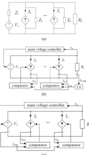
The Type I connection is shown in Fig. 2 (a). Each branch represents a converter, which is basically a Th´evevin source. For the control without current-sharing loop, the branches are simply connected in parallel.
No other extra action is taken among the converters to achieve current balance. However, the absence of a current-sharing loop imposes some specific requirements on the individual branches in order to provide natural current sharing. This has been commonly known as the droop method [1]. Specifically, each converter, in the absence of a current-sharing loop, should have a finite output resistance at steady state, which results in obvious droop characteristic of the converter. Otherwise, any small discrepancy of Vi and/or Zi will cause severe current imbalance among the converters. For Type I connection with current-sharing loop, since all converters are Th´evenin sources, output regulation and current sharing are achieved by controlling V1, V2, · · · ,
Vn and/or the output impedance Z1, Z2, · · · , Zn. The control structure is shown in Fig. 2(b). In this configuration, each converter is a dependant voltage source, in which the output voltage is controlled directly. The currents sensed from different converters are programmed to obtain a common current sharing control signal, which will be compared with the feedback currents to regulate individual equivalent voltages V1, V2,
· · · , Vn. The objective is to shrink the discrepancy of the converters. Thus, all converters share the load equally.
B. Type II
For the Type II connection shown in Fig. 3 (a), one converter serves as the voltage (Th´evenin) source and others are current (Norton) sources. The control structure without current-sharing loop is shown in Fig. 3 (b). There is a main voltage feedback loop, which acts on the voltage (Th´evenin) source to regulate the output voltage. Other branches are under current-mode control (peak-current-mode control is applied in the paper), that the objective is to make all individual output currents share the same portion of the load current. For Type II configuration with current-sharing loop, the control structure is shown in Fig. 3 (c). Again, there is a main voltage loop to control the voltage source. The current control signal for the current sources will be derived from the voltage source branch. This current control signal is then compared with the individual current of the
N −1 converters to achieve current sharing. This method is commonly known as masterslave current-sharing method [1], where the voltage source is the master and the current sources are the slaves whose currents are programmed to follow the master’s.
C. Type III
as current-sharing. A simple implementation can be found in Iu et al. [4].
Finally, for the Type III configuration with current-sharing loop, all converters are under current-mode con-trol so that they behave as good current sources. Current-programming methods, such as master-slave method or average method, can be used to generate the common current-sharing control signal. The amplified errors bet-ween the current sharing control signal and the feedback currents are injected to the feedback loop as shown in Fig. 4 (c).
IV. BUCK DC-DC CONVERTER
Topology DC-DC converter Buck model is used in this study. Current Mode Control Method is an appropriate concept for the parallel system, because this study developed three DC-DC converters in parallel non-iden-tical parameters of the inductor. DC-DC converter Buck model, operated in a continuous state if the current flow-ing in the inductor L1, will never reach commutation zero
during the cycle occurs. This phenomenon can be described as follows: the first time on the condition ON MOSFET, VL= Vi- Voand the inductor current ILrises
linearly while the diode in reverse biased so no current flows in the D1. Both at the time of MOSFET in the OFF state diode becomes forward biased so that VL = - Vo,
this condition causes the inductor current decreases gra-dually.
The role of inductor L1 is to transfer energy from the
input to output with a large stored energy during ON and released at OFF condition, the magnitude is:
2 2 1 L I L
E (3)
and
dt dI L
V L
L (4)
IL was a change occurs in two conditions namely,
ON condition when the amount is:
on on
t L i o on
L L t V V dt L V I 0 ).
( (5)
OFF condition when the amount is:
off
off
t o off
L L L t V dt L V
I 0 . (6)
it can be assumed that the stored energy component of L in one period T resulting from the two conditions above the current changes are:
0
ILon ILoff (7) So, the equation is as:
0 ). ( ). ( L t V V L t V
Vi o on i o on (8)
In the Fig. 5 can be seen that ton= D. T, while the toff=
T - T. D, where D is a scalar quantity called the Duty Cycle.
The value of D is between 0 and 1, so the decrease in D formula is: 0 ) . .( . ).
(Vi Vo DT Vo T DT (9) The equation can be written as the following,
i o i o V V D or V D
V . (10)
V. GBELL MEMBERSHIP FUNCTION
Membership function is a curve that shows the mapping of data input points to the value of membership or so-called degree of membership, with the interval is between 0 and 1. In general the parameters a and c is the membership function as the following equation:
(11)
b parameters in general is positive, c parameter is located in the middle of the curve while a parameter is the in-flection point that determines the width of the narrow curve shape. [8.9] Membership Function used in this re-search is 5 gbellmf. For input Ve (Verror), ΔVe (delta
Error) and Output membership function can be seen in Fig. 6. The range of output membership function deter-mines the ability to control action on both the input vari-ables Ve and ΔVe. So the range of output membership function is very influential on the output quality of a system designed.
VI
.
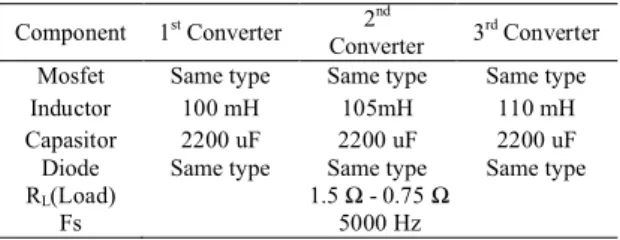
RESULTS AND DISCUSSIONTable 1 is a parallel DC-DC converter Parameters. Pa-rallel DC-DC converter non-identical is composed of ge-neral components and Current Mode Control is subtract-ing of current method from each converter. Analysis and simulation use Simulink of Matlab.
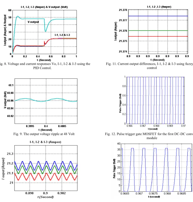
These results provide a positive contribution to the sta-bility of output voltage, current distribution of each DC-DC converter and output voltage ripple which is smaller than the output voltage ripple when the parallel system does not use control. Output voltage response to load about is 30 Ampere and output voltage still stable ± 48 volts although the initial response to the voltage rises to 53 volts. This condition takes only 0.05 seconds. Fig. 7 is a response to the output voltage Vo and I1, I2, and I3,
with a change in RL= 1.5 Ω to 0.75Ω using Gbell Mem
-bership Function. While the transient responses, the out-put voltage decreases to 30 volts, caused by a change in the load from 30 Ampere up to about 63 Ampere.
This phenomenon also takes approximately 0.1 seconds to reach a stable output voltage again. Distribu-tion of current to the load on the DC-DC converter based on the initial FLC has a quite big difference between each module about tens of mA. After a change of the load occurs, however, the difference of current dis-tribution of each converter module becomes dozens mA. The difference between the first and second converters is only 0.0001182 mA, and the difference between the first and third converter becomes 0.0001095mA.
Fig. 8 is the result of DC-DC converters in parallel by using PID controller but the response has a little change compared to the control system by using FLC. Rise-time is really fast, the voltage give a little increase in the beginning. At steady-state, the distribution difference of 10A load is tens mA.
When the load is increased to 21 Ampere of each mo-dule DC-DC converter, the differences of current distri-bution for each DC-DC converter change into 0.1 mA up to 1 mA.
TABLE 1.
DC-DC CONVERTER PARAMETER
The output voltage ripple is less than 10 mV, while the systems are not using controller, the ripple is in range 100 mV. See Fig. 9 for comparing the results of paper [2]. The output voltage ripple is 39 mV by using PID and Fuzzy state control. The output voltage ripple is 11 mV. In this study, the systems to minimize the ripples have been achieved. From the study results, the difference of current distribution of each DC-DC converter module give a good performance and the difference of current distribution is range from 4 mA up to 8 mA. Fig. 10 is an enlarged figure of current distribution on the full load and PID Control as a controller in this system. Fig. 11 shows the difference in the distribution of current res-ponse to the full load using FLC.
The difference between the first DC-DC converter mo-dule and the second DC-DC converter momo-dule is 0.0001182 Ampere (0.1 mA), while the difference of current distribution between the first converter module and the third DC-DC converter module is 0.0001095 Ampere (0.1 mA) .
The results of the response Fig. 12 is the MOSFET gate trigger pulse to the module DC-DC converter first, a large voltage is 1 Volt is a system integrator to control the control on this research, in order to balance the current distribution as even greater value. This technique is done in analyzing parallel DC-DC converters non-identical parameters.
The results of the response Fig. 13 is the MOSFET gate trigger pulse for the DC-DC converter module for the second and third. The tension is about 35 volts and the integrator use to control system so that current distri-bution becomes equal from each DC-DC converter.
Fig. 14 is percentage response current distribution bet-ween I1and I2,I1and I3. The figure shows the difference
in the distribution of current in the small load become 10%, but the difference of current distribution is below 5% at the large load. The design of parallel DC-DC con-verter using FLC had a good response at large load.
VII. CONCLUSION
This study produced DC-DC converters system in parallel with the inductance parameters L1 ≠ L2 ≠ L3,
using Fuzzy Logic Control and PID control systems as an analysis comparison. The improvement of output volt-age ripple is about 10 mV, and the difference of current distribution to the load becomes 0.1 mA (near 0%). Those three different DC-DC converters module (The first, second, and third) resulting the same number that is 21.28 Ampere by using FLC. Meanwhile, by using of PID control made the difference of current distribution become 4 mA - 8 mA, in which the current distribution of each DC-DC converter module for the first
conver-Fig 1. Block circuit DC-DC converter three non-identical parallel
ter is 21.13, the second converter is 21.13 Ampere and the third converter is 21.12 Ampere. In conclusion, some system repairmen had been carried out to the parallel DC-DC converter non-identical.
REFERENCES
[1] V. J. Thottuvelil and G. C. Verghese, 1998, “Analysis and control design of paralleled DC/DC converters with current sharing”,
IEEE Trans. on Power Electronics, Vol. 13, No. 4, pp. 635-644. [2] M. Milanovic and Dusan G, “Buck converter digitally controlled
by a fuzzy state-space controller”. HAIT Journal of Science and Engineering B, Vol. 2, Issue 5-6, pp. 638-654 Copyright ©2005 Holon Academic Institute of Technology.
[3] B. Tomescu, 2001, “On the use of fuzzy logic to control paralleled DC-DC converters”, Dissertation submitted to the Faculty of the Virginia Polytechnic Institute and State University in Partial Fulfillment of the Requirements for the Degree of Doctor of Philosophy in Electrical and Computer Engineering, Blacksburg, Virginia.
[4] S. Luo, Z. Ye, R.-L. Lin, and F. C. Lee, 1999, “A classification and evaluation of paralleling methods for power supply mo-dules”,Proc. IEEE Power Electron. Specialists Conf. Record, pp. 901–908.
[5] B. Choi, “Comparative study on paralleling schemes of converter modules for distributed power applications”,IEEE Trans. on Ind. Electronics, vol. 45, no. 2, pp. 194–199, March 1998.
[6] Siri. K, Lee. C.Q, Wu. T.E., 1992, “Current distribution control for parallel connected converter”,IEEE Transactions on Aero-space and Electronic Systems, Vol. 28, No.3.
[7] Mattavelli. P, L. Rossetto, G. Spiazzi, and P.Tenti, 1995, “General Purpose fuzzy controller for DC/DC converters.”IEEE PECS Rec., pp. 723-730.
[8] Wing-Chi So, Chi K. Tse, Yim-Shu Lee, 1996, “Development of a fuzzy logic controller for DC/DC converters: design, computer simulation, and experimental evaluation”,IEEE Transactions on Power Electronics,Vol.11, No. 1.
[9] Y. Huang and C. K. Tse,2007, “Classification of parallel DC/DC converters part I: Circuits theory”,IEEE,pp. 1010-1013.
(a)
(b)
Fig. 2. (a) Configuration DC-DC converter Type I (b) The current sharing loop system
Component 1stConverter 2nd
Converter 3rdConverter Mosfet Same type Same type Same type
Inductor 100 mH 105mH 110 mH
Capasitor 2200 uF 2200 uF 2200 uF
Diode Same type Same type Same type RL(Load) 1.5 Ω - 0.75 Ω
(a)
(b)
(c)
Fig. 3.(a) Configuration DC-DC converter Type II. (b) Configuration without loop current sharing (c) Configuration using the loop current
sharing
(a)
(b)
(c)
Fig. 4. (a) Configuration DC-DC converter type III (b) Configuration without loop current sharing (c) Configuration using the loop current
sharing
Fig. 5. DC-DC converter model of Buck
Fig. 6. Membership function output
Fig. 7. Voltage and current responses Vo, I-1, I-2 & I-3 using fuzzy logic control
0 20 40 60 80 100 120
0 0.2 0.4 0.6 0.8 1
Control Action
De
gre
e o
f m
em
be
rsh
ip
Fig. 8. Voltage and current responses Vo, I-1, I-2 & I-3 using the PID Control.
Fig. 9. The output voltage ripple at 48 Volt
Fig. 10. Output current differences, I-1, I-2 & I-3 using PID Control.
Fig. 11. Current output differences, I-1, I-2 & I-3 using fuzzy logic control
Fig. 12. Pulse trigger gate MOSFET for the first DC-DC converter module
Fig. 13. Pulse trigger gate MOSFET for the second and the third DC-DC converters module