Front cover
Implementing the IBM
SAN Volume Controller
and FlashSystem 820
Jon Tate
Danny Bryant
Christian Burns
Joao Marcos Leite
Denis Senin
Enhance storage capabilities with
sophisticated virtualization
Move data among virtualized
storage systems
Optimize flash storage
deployments automatically
International Technical Support Organization
Implementing the IBM SAN Volume Controller and
FlashSystem 820
© Copyright International Business Machines Corporation 2013. All rights reserved. First Edition (September 2013)
This edition applies to the hardware and software listed in Appendix B, “Example environment details” on page 139.
Note: Before using this information and the product it supports, read the information in “Notices” on
Contents
Notices . . . vii
Trademarks . . . viii
Preface . . . ix
Authors . . . .x
Now you can become a published author, too! . . . xii
Comments welcome. . . xii
Stay connected to IBM Redbooks . . . xii
Chapter 1. Introduction to IBM SAN Volume Controller and IBM FlashSystem 820 . . . 1
1.1 IBM System Storage SAN Volume Controller . . . 2
1.1.1 IBM System Storage SAN Volume Controller overview . . . 2
1.1.2 IBM System Storage SAN Volume Controller design overview . . . 2
1.1.3 SAN Volume Controller architecture and components . . . 5
1.1.4 IBM SmartCloud Virtual Storage Center . . . 7
1.2 SAN Volume Controller hardware and software updates of interest to this book . . . 8
1.2.1 Hardware updates for SVC . . . 8
1.2.2 New features in SVC Storage Software version 7.1 . . . 9
1.3 Introduction to IBM FlashSystem storage systems . . . 10
1.3.1 IBM FlashSystem storage system portfolio. . . 11
1.3.2 Differences between IBM FlashSystem families and models . . . 12
1.4 Introduction to flash solid-state technology . . . 14
1.4.1 Types of flash memory used in IBM FlashSystems . . . 15
1.4.2 Unique characteristics. . . 16
1.4.3 Single-level cell memory . . . 16
1.4.4 Multi-level cell memory . . . 17
1.4.5 Solid-state drive architecture. . . 18
1.4.6 Flash memory lifetime . . . 21
1.5 IBM FlashSystem storage systems technology overview . . . 22
1.5.1 IBM FlashSystem storage systems architecture . . . 24
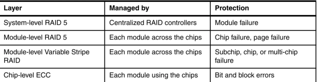
1.5.2 Data protection and redundancy in the IBM FlashSystem 820 . . . 32
1.5.3 RAID technologies . . . 32
1.5.4 Flash memory protection. . . 35
1.5.5 RAID rebuild process . . . 35
1.5.6 Differences between IBM FlashSystem storage systems and SSD-based storage systems. . . 36
1.5.7 Usage considerations for IBM FlashSystem storage systems . . . 38
Chapter 2. Usage considerations and scenarios . . . 41
2.1 Usage considerations . . . 42
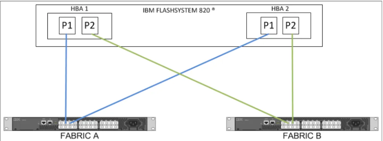
2.1.1 Port assignment scenarios and related considerations. . . 42
2.1.2 SAN Volume Controller Stretched Cluster . . . 46
2.1.3 Port masking on SVC with IBM FlashSystem 820 . . . 46
2.1.4 Host multipathing . . . 47
2.1.5 Considerations regarding number of FlashSystem per I/O group. . . 47
2.2 Usage scenarios . . . 48
2.2.1 All FlashSystem usage scenario . . . 48
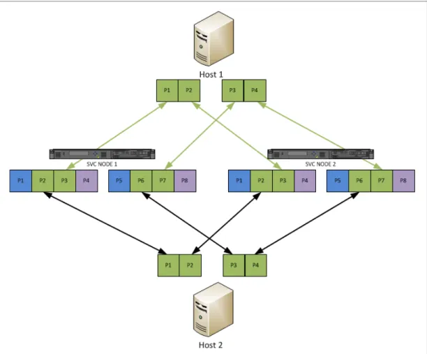
2.2.2 FlashSystem with SAN Volume Controller volume mirroring . . . 51
2.3.1 Volume mirroring between two FlashSystem storage systems. . . 57
2.3.2 Volume mirroring between a FlashSystem storage system and a non-flash storage system . . . 58
2.4 Using FlashSystem with SVC Easy Tier . . . 58
2.4.1 General considerations with Easy Tier . . . 58
2.4.2 Separate FlashSystem storage pools and existing storage pools that are not using IBM Easy Tier . . . 59
2.5 FlashSystem with SVC replication . . . 60
2.6 Failure protection capabilities . . . 61
2.6.1 FlashSystem 820 hardware failure protection. . . 61
2.6.2 SVC hardware failure protection . . . 62
2.6.3 SAN fabric failure considerations . . . 62
Chapter 3. Planning and installation of the IBM FlashSystem 820. . . 63
3.1 Physical device accessibility . . . 64
3.1.1 Physical layout . . . 64
3.1.2 Rack placement and cabling considerations. . . 64
3.2 Physical cabling . . . 66
3.2.1 FC port speed settings . . . 66
3.2.2 Cabling methods . . . 66
3.2.3 FC cable type . . . 67
3.2.4 Ethernet management cabling . . . 67
3.3 Power and cooling considerations . . . 68
3.3.1 Power requirements . . . 68
3.3.2 Cooling requirements . . . 68
3.4 Performance Guidelines . . . 69
3.4.1 VMware VAAI . . . 69
3.4.2 Performance Redpaper. . . 69
3.4.3 Performance data and statistics collection . . . 70
Chapter 4. Configuration and administration . . . 77
4.1 Setup and configuration of IBM FlashSystem for use with SAN Volume Controller . . . 78
4.1.1 Configuring the FlashSystem management IP addresses . . . 78
4.1.2 FlashSystem management tools. . . 80
4.1.3 IBM FlashSystem feature licenses . . . 83
4.1.4 Configuring additional network settings . . . 85
4.1.5 email notifications and call home . . . 90
4.1.6 Fibre Channel port settings . . . 94
4.1.7 Logical unit creation and access policies . . . 99
4.2 Port masking and SAN zoning configuration. . . 108
4.2.1 SAN Volume Controller Fibre Channel port masking setup . . . 108
4.2.2 Host Fibre Channel port masking setup . . . 110
4.2.3 SAN zoning setup . . . 110
4.3 SAN Volume Controller MDisk configuration. . . 111
4.3.1 MDisk LUN configuration on IBM FlashSystem 820 . . . 111
4.3.2 Storage pool configuration guidelines . . . 113
4.3.3 Quorum disk allocation . . . 113
4.3.4 Storage pool extent size . . . 116
4.3.5 MDisk mapping and storage pool creation using the CLI . . . 117
4.3.6 MDisk mapping and storage pool creation using the GUI. . . 118
Chapter 5. Diagnostics, planned outages, and troubleshooting . . . 123
5.1 I/O group volume migration for planned outages . . . 124
5.3 Volume migration to another storage pool for planned outages . . . 125
5.4 Call home features of SAN Volume Controller and FlashSystem storage systems . . 126
5.4.1 SVC call home . . . 126
5.4.2 IBM FlashSystem call home and event notification. . . 127
5.5 Easy Tier and FlashSystem planned outages. . . 127
5.6 Hardware replacement guide for IBM FlashSystem storage systems. . . 128
Appendix A. FlashSystem CLI commands used in the example environment . . . 129
Configuring the example IBM FlashSystem storage systems using the CLI . . . 130
Setting the management control processor host name. . . 130
Setting the Domain Name Service domain . . . 130
Configuring the call home feature . . . 131
Configuring the events notification feature . . . 131
Configuring Fibre Channel port settings using the CLI . . . 132
Configuring logical unit numbers and access policies using the CLI . . . 134
Appendix B. Example environment details. . . 139
Example environment hardware components . . . 140
List of hardware components . . . 140
Example environment firmware and software levels . . . 141
Example environment topology . . . 141
Related publications . . . 143
IBM Redbooks . . . 143
Other publications . . . 143
Online resources . . . 144
Notices
This information was developed for products and services offered in the U.S.A.
IBM may not offer the products, services, or features discussed in this document in other countries. Consult your local IBM representative for information on the products and services currently available in your area. Any reference to an IBM product, program, or service is not intended to state or imply that only that IBM product, program, or service may be used. Any functionally equivalent product, program, or service that does not infringe any IBM intellectual property right may be used instead. However, it is the user's responsibility to evaluate and verify the operation of any non-IBM product, program, or service.
IBM may have patents or pending patent applications covering subject matter described in this document. The furnishing of this document does not grant you any license to these patents. You can send license inquiries, in writing, to:
IBM Director of Licensing, IBM Corporation, North Castle Drive, Armonk, NY 10504-1785 U.S.A.
The following paragraph does not apply to the United Kingdom or any other country where such provisions are inconsistent with local law: INTERNATIONAL BUSINESS MACHINES CORPORATION
PROVIDES THIS PUBLICATION "AS IS" WITHOUT WARRANTY OF ANY KIND, EITHER EXPRESS OR IMPLIED, INCLUDING, BUT NOT LIMITED TO, THE IMPLIED WARRANTIES OF NON-INFRINGEMENT, MERCHANTABILITY OR FITNESS FOR A PARTICULAR PURPOSE. Some states do not allow disclaimer of express or implied warranties in certain transactions, therefore, this statement may not apply to you.
This information could include technical inaccuracies or typographical errors. Changes are periodically made to the information herein; these changes will be incorporated in new editions of the publication. IBM may make improvements and/or changes in the product(s) and/or the program(s) described in this publication at any time without notice.
Any references in this information to non-IBM websites are provided for convenience only and do not in any manner serve as an endorsement of those websites. The materials at those websites are not part of the materials for this IBM product and use of those websites is at your own risk.
IBM may use or distribute any of the information you supply in any way it believes appropriate without incurring any obligation to you.
Any performance data contained herein was determined in a controlled environment. Therefore, the results obtained in other operating environments may vary significantly. Some measurements may have been made on development-level systems and there is no guarantee that these measurements will be the same on generally available systems. Furthermore, some measurements may have been estimated through extrapolation. Actual results may vary. Users of this document should verify the applicable data for their specific environment.
Information concerning non-IBM products was obtained from the suppliers of those products, their published announcements or other publicly available sources. IBM has not tested those products and cannot confirm the accuracy of performance, compatibility or any other claims related to non-IBM products. Questions on the capabilities of non-IBM products should be addressed to the suppliers of those products.
This information contains examples of data and reports used in daily business operations. To illustrate them as completely as possible, the examples include the names of individuals, companies, brands, and products. All of these names are fictitious and any similarity to the names and addresses used by an actual business enterprise is entirely coincidental.
COPYRIGHT LICENSE:
This information contains sample application programs in source language, which illustrate programming techniques on various operating platforms. You may copy, modify, and distribute these sample programs in any form without payment to IBM, for the purposes of developing, using, marketing or distributing application programs conforming to the application programming interface for the operating platform for which the sample programs are written. These examples have not been thoroughly tested under all conditions. IBM, therefore, cannot guarantee or imply reliability, serviceability, or function of these programs.
Trademarks
IBM, the IBM logo, and ibm.com are trademarks or registered trademarks of International Business Machines Corporation in the United States, other countries, or both. These and other IBM trademarked terms are marked on their first occurrence in this information with the appropriate symbol (® or ™), indicating US registered or common law trademarks owned by IBM at the time this information was published. Such trademarks may also be registered or common law trademarks in other countries. A current list of IBM trademarks is available on the Web at http://www.ibm.com/legal/copytrade.shtml
The following terms are trademarks of the International Business Machines Corporation in the United States, other countries, or both:
Calibrated Vectored Cooling™ Cognos®
Easy Tier® FlashCopy® FlashSystem™
Global Technology Services® IBM FlashSystem™ IBM SmartCloud® IBM® Intelligent Cluster™ Real-time Compression™ Redbooks® Redpaper™ Redbooks (logo) ® Smarter Planet® Storwize® System Storage® System x® Tivoli® XIV®
The following terms are trademarks of other companies:
VSR, and the Texas Memory Systems logo are trademarks or registered trademarks of Texas Memory Systems, an IBM Company.
Intel Xeon, Intel, Intel logo, Intel Inside logo, and Intel Centrino logo are trademarks or registered trademarks of Intel Corporation or its subsidiaries in the United States and other countries.
Linux is a trademark of Linus Torvalds in the United States, other countries, or both.
Windows, and the Windows logo are trademarks of Microsoft Corporation in the United States, other countries, or both.
Java, and all Java-based trademarks and logos are trademarks or registered trademarks of Oracle and/or its affiliates.
Preface
In today’s 24 x 7 world, there is likely not a business on this planet, IBM® Smarter Planet® or not, that finds that their storage requirements are growing too fast and demand is starting to outpace supply. Not only this, but in this cost-conscious environment of today, the costs of managing this growth are likely to be eating into the IT budget.
One way to make better use of existing storage without adding more complexity to the infrastructure is the IBM System Storage® SAN Volume Controller (SVC). For many years now this has helped business become more flexible, agile, and introduced an extremely efficient storage environment. SAN Volume Controller is designed to deliver the benefits of storage virtualization in environments from large enterprises to small businesses and midmarket companies.
Virtualizing storage with SAN Volume Controller helps make new and existing storage more effective. SAN Volume Controller includes many functions that are traditionally deployed separately in disk systems. By including these in a virtualization system, SAN Volume Controller standardizes functions across virtualized storage for greater flexibility and potentially lower costs.
Now, with IBM FlashSystem™ storage, SAN Volume Controller is enabled to extend its reach and benefit all virtualized storage. For example, IBM Easy Tier® optimizes use of flash storage. And IBM Real-time Compression™ enhances efficiency even further by enabling the storage of up to five times as much active primary data in the same physical disk space.
In this IBM Redbooks® publication, we show how to integrate the IBM FlashSystem 820 to provide storage to the SAN Volume Controller, and show how they are designed to operate seamlessly together, reducing management effort.
In this book, which is aimed at pre- and post-sales support, storage administrators, and people that want to get an overview of this new and exciting technology, we show the steps required to implement the IBM FlashSystem 820 in an existing SAN Volume Controller environment. We also highlight some of the new features in SAN Volume Controller that increase performance.
If you are not already familiar with the SAN Volume Controller, it is beneficial to read the following IBM Redbooks publications:
Implementing the IBM System Storage SAN Volume Controller V6.3, SG24-7933
Implementing the IBM Storwize V7000 V6.3, SG24-7938
Real-time Compression in SAN Volume Controller and Storwize V7000, REDP-4859
IBM SAN Volume Controller and IBM FlashSystem 820: Best Practices and Performance Capabilities, REDP-5027
IBM FlashSystem 710 and IBM FlashSystem 810, TIPS1002
IBM FlashSystem 720 and IBM FlashSystem 820, TIPS1003
Authors
This book was produced by a team of specialists from around the world working at the home of virtualization, IBM Hursley Labs, UK.
Jon Tate is a Project Manager for IBM System Storage SAN
Solutions at the International Technical Support Organization (ITSO), San Jose Center. Before joining the ITSO in 1999, he worked in the IBM Technical Support Center, providing Level 2/3 support for IBM storage products. Jon has over 27 years of experience in storage software and management, services, and support, and is both an IBM Certified Consulting IT Specialist and an IBM SAN Certified Specialist. He is also the UK Chairman of the Storage Networking Industry Association.
Danny Bryant is a Client Technical Specialist (CTS) for
IBM System Storage for Systems Technology Group (STG) in Melbourne, Australia, Before joining STG, he worked in IBM Global Technology Services® (GTS) as a design and implementation specialist for IBM System Storage within enterprise accounts. Danny has 10 years of experience in the IT industry and a strong infrastructure background. He also specializes in VMware.
Christian Burns is an IBM Storage Solution Architect based in
New Jersey. As a member of the Storage Solutions Engineering team in Littleton, MA, he works with clients, IBM Business Partners, and IBMers worldwide, designing and implementing storage solutions that include various IBM products and technologies. Christian’s areas of expertise include IBM Real-time Compression, SVC, XIV®, and IBM FlashSystem. Before joining IBM, Christian was the Director of Sales Engineering at IBM Storwize®, prior to its becoming IBM Storwize. He brings over a decade of industry experience in the areas of sales engineering, solution design, and software development. Christian holds a BA degree in Physics and Computer Science from Rutgers College.
Thanks to the following people for their contributions to this project: Ian Boden Carlos Fuente Evelyn Perez Greg Shepherd Vairavan Sockalingam Barry Whyte IBM Hursley Matt Key Adrian Flores-serafin Kevin Powell Bobby Sumners Brad Duncan David Drinnan Travis Dockery IBM US
Joao Marcos Leite is an IT Specialist who joined IBM Brazil in
2000. He has worked for the IBM Systems and Technology Group in the field of storage solutions design for clients, and is currently working as an Advanced Technical Skills (ATS) member for the IBM Growth Markets Unit (GMU) in Latin America, focused on Storage Software. His areas of expertise include storage virtualization and storage management, and he co-authored previous updates to the SAN Volume Controller Implementation, and to the IBM Tivoli® Storage Productivity Center V4.2 Release Guide Redbooks publications. Joao graduated as a Data Processing Technologist from the Universidade Federal do Parana in Curitiba, Brazil. He has 32 years of experience as an IT Specialist and is a member of the Technology Leadership Council Brazil (TLC-BR), an affiliate of the IBM Academy of Technology. Joao is a Thought Leader (Level 3) Certified IT Specialist by IBM and holds a title of Distinguished IT Specialist by The Open Group.
Denis Senin is an ATS CEE Storage Specialist in IBM Russia.
He has 10 years of experience in IT industry and has worked at IBM for 8 years. Denis holds a Master’s degree of
design-engineer of computer systems from The Moscow State Institute of Radiotechnics, Electronics and Automatics, and has a background of systems design and development. His current areas of expertise include Open Systems, high-performance, disaster recovery, and flash memory-based storage solutions.
Now you can become a published author, too!
Here’s an opportunity to spotlight your skills, grow your career, and become a published author—all at the same time! Join an ITSO residency project and help write a book in your area of expertise, while honing your experience using leading-edge technologies. Your efforts will help to increase product acceptance and customer satisfaction, as you expand your network of technical contacts and relationships. Residencies run from two to six weeks in length, and you can participate either in person or as a remote resident working from your home base.
Find out more about the residency program, browse the residency index, and apply online at:
ibm.com/redbooks/residencies.html
Comments welcome
Your comments are important to us!
We want our books to be as helpful as possible. Send us your comments about this book or other IBM Redbooks publications in one of the following ways:
Use the online Contact us review Redbooks form that is found at:
ibm.com/redbooks
Send your comments in an email to:
[email protected] Mail your comments to:
IBM Corporation, International Technical Support Organization Dept. HYTD Mail Station P099
2455 South Road
Poughkeepsie, NY 12601-5400
Stay connected to IBM Redbooks
Find us on Facebook:
http://www.facebook.com/IBMRedbooks Follow us on Twitter:
http://twitter.com/ibmredbooks Look for us on LinkedIn:
http://www.linkedin.com/groups?home=&gid=2130806
Explore new Redbooks publications, residencies, and workshops with the IBM Redbooks weekly newsletter:
https://www.redbooks.ibm.com/Redbooks.nsf/subscribe?OpenForm Stay current on recent Redbooks publications with RSS Feeds:
Chapter 1.
Introduction to IBM SAN Volume
Controller and IBM FlashSystem 820
This chapter provides an introduction to IBM FlashSystem storage systems. It describes the primary concepts concerning flash memory technology, including design architecture, internal processes, and the advantages and limitations of flash. The architecture of the
IBM FlashSystem 820 is covered and we provide a brief introduction to the IBM SAN Volume Controller, including an overview of the latest software and hardware updates.
The following topics are covered:
Introduction to the IBM SAN Volume Controller
Introduction to the IBM FlashSystem storage system
Architecture and internal processes of the IBM FlashSystem 820
Introduction to flash memory technology
Usage considerations of traditional and flash-based storage systems
Unique benefits of the IBM FlashSystem storage system implementation
1.1 IBM System Storage SAN Volume Controller
The IBM System Storage SAN Volume Controller (SVC) is a storage virtualization solution that helps to increase the utilization of existing storage capacity and centralize the
management of multiple controllers in an open-system storage area network (SAN) environment.
The SAN Volume Controller supports attachment to both IBM and non-IBM storage systems. It enables storage administrators to reallocate and scale storage capacity and make changes to underlying storage systems without disruption to applications.
In this section, we provide an overview of the SVC. Details about some of the new features and capabilities that were introduced with SAN Volume Controller 7.1 are described in section 1.2, “SAN Volume Controller hardware and software updates of interest to this book” on page 8.
1.1.1 IBM System Storage SAN Volume Controller overview
The IBM System Storage SAN Volume Controller, machine type 2145, and accompanying software, provides the ability to simplify storage infrastructure, utilize storage resources more efficiently, improve personnel productivity, and increase application availability.
SAN Volume Controller pools storage volumes from IBM and non-IBM disk arrays into a single reservoir of capacity, which can be managed from a central point. SAN Volume Controller also allows data to be migrated between heterogeneous disk arrays without disruption to applications. By moving copy services functionality into the network, SVC allows you to use a standardized suite of copy services tools that can be applied across the entire storage infrastructure, irrespective of storage vendor restrictions that normally apply for the individual disk controllers in use.
Additionally, SAN Volume Controller adds functions to the infrastructure that might not be present in each virtualized subsystem. Examples include thin provisioning, automated tiering, volume mirroring, and data compression.
1.1.2 IBM System Storage SAN Volume Controller design overview
The IBM System Storage SAN Volume Controller is designed to handle the following tasks:
Combine storage capacity from multiple vendors into a single repository of capacity with a central management point
Help increase storage utilization by providing host applications with more flexible access to capacity
Help improve productivity of storage administrators by enabling management of combined storage volumes from a single, user-friendly interface
Support improved application availability by insulating host applications from changes to the physical storage infrastructure
Note: Some of the SAN Volume Controller functions mentioned above are included in the
base virtualization license, although for others an additional license might need to be purchased.
Enable a tiered storage environment, in which the cost of storage can be better matched to the value of data
Support advanced copy services, from higher-cost to lower-cost devices and across subsystems from multiple vendors
SAN Volume Controller combines hardware and software into a comprehensive, modular appliance. Using IBM System x® server technology in highly reliable clustered pairs, the SAN Volume Controller has no single points of failure. The SAN Volume Controller software is a highly available cluster that is optimized for performance and ease of use.
Storage utilization
The SAN Volume Controller is designed to help increase the amount of storage capacity that is available to host applications. By pooling the capacity from multiple disk arrays within the SAN, it enables host applications to access capacity beyond their island of SAN storage. The Storage Networking Industry Association (SNIA) estimates that open systems disk utilization in a non-virtualized environment is currently only between 30% - 50%. With storage
virtualization, this utilization can grow up to 80%, on average.
Scalability
A SAN Volume Controller configuration can start with a single I/O group. An I/O group is a pair of high performance, redundant Intel processor-based servers, referred to as
nodes
orstorage engines
. Highly available I/O groups are the basic configuration of a cluster. Adding additional I/O groups can help increase cluster performance and bandwidth.SAN Volume Controller can scale out to support up to four I/O groups. SAN Volume Controller Version 7.1 supports up to 2048 host servers when using CF8 and CG8 engines. For every cluster, the SVC supports up to 8192 volumes, each one with up to 256 TB in size, and a total virtualized capacity up to 32 PB.
This configuration flexibility means that SAN Volume Controller configurations can start small with an attractive price to suit smaller environments or pilot projects, and then can grow with your business to manage very large storage environments.
Management
The SAN Volume Controller is managed at the cluster level, providing a single point of control over all the managed storage. The SAN Volume Controller provides a comprehensive, easy-to-use graphical user interface (GUI) for central management. This simple interface incorporates the Storage Management Initiative Specification (SMI-S) application programming interface (API), and further demonstrates the commitment of IBM to open standards. The SAN Volume Controller cluster can also be managed and monitored through a comprehensive command-line interface (CLI) via Secure Shell (SSH), enabling the use of scripts and automate repeatable operations.
The SAN Volume Controller GUI is designed for ease of use and includes many built-in IBM guidelines that simplify storage provisioning and enables new clients to get started quickly with a rapid learning curve.
Clients using IBM Tivoli Storage Productivity Center, IBM Systems Director, and IBM Tivoli Storage FlashCopy® Manager can take further advantage of integration points with the SVC.
Note: For the most up-to-date SVC configuration limits, refer to the Configuration Limits
and Restrictions website for the latest SAN Volume Controller version:
As with managing the SVC under Tivoli Storage Productivity Center, IBM Systems Director will be enabled to perform the most common day-to-day activities for SVC without ever needing to leave the IBM Systems Director user interface.
For historic performance and capacity management from both the host and the virtualized storage devices’ perspectives, Tivoli Storage Productivity Center helps clients with an end-to-end view and control of the virtualized storage infrastructure. Regarding data protection, Tivoli Storage FlashCopy Manager helps integrate the SVC FlashCopy function with major applications for consistent backups and restores.
Linking infrastructure performance to business goals
By pooling storage into a single reservoir, the SAN Volume Controller helps insulate host applications from physical changes to the storage pool, minimizing disruption. The SVC simplifies storage infrastructure by including a dynamic data-migration function, allowing for online volume migration from one device to another. By using this function, administrators can reallocate, scale storage capacity, and apply maintenance to storage subsystems without disrupting applications, increasing application availability.
With the SVC, your business can build an infrastructure from existing assets that is simpler to manage, easier to provision, and can be changed without impact to application availability. Businesses can use their assets more efficiently and actually measure the improvements. They can allocate and provision storage to applications from a single view and know the effect on their overall capacity instantaneously. They can also quantify improvements in their application availability to enable better quality of service goals. These benefits help
businesses manage their costs and capabilities more closely, linking the performance of their infrastructure to their individual business goals.
Tiered storage
In most IT environments, inactive data makes up the bulk of stored data. The SAN Volume Controller helps administrators control storage growth more effectively by moving low-activity or inactive data into a hierarchy of lower-cost storage. Administrators can free disk space on higher-value storage for more important, active data. It is achieved by easily creating various groups of storage, or
storage pools
, corresponding to underlying storage with various characteristics. Examples are speed and reliability. With the SAN Volume Controller, you can better match the cost of the storage used to the value of data placed on it.Copy services
With many conventional SAN disk arrays, copy services can only be performed within the array, or between identical arrays. The SAN Volume Controller enables administrators to apply a single set of advanced copy services, such as IBM FlashCopy, Metro Mirror, and Global Mirror services, across multiple storage subsystems from various vendors.
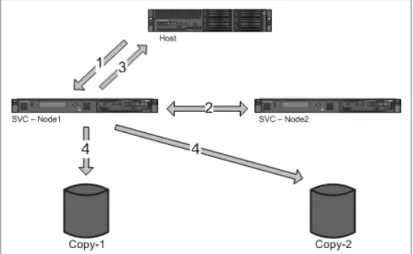
A volume can also be mirrored locally between two different storage subsystems for high availability. This volume mirroring function is the basis for stretched cluster configurations where the I/O group nodes are spread over two different locations to build an even more resilient solution.
Technology for an on demand environment
Businesses are facing growth in critical application data that is supported by complex heterogeneous storage environments, while their staffs are overburdened. The SAN Volume Controller is one of many offerings in the IBM System Storage portfolio that is essential for an on demand storage environment. These offerings can help you simplify your IT infrastructure, manage information throughout its lifecycle, and maintain business continuity.
1.1.3 SAN Volume Controller architecture and components
SAN-based storage is managed by the SAN Volume Controller in one or more
I/O groups
(
pairs
) of SVC hardware nodes, referred to as aclustered system
. These nodes are attached to the SAN fabric, along with storage controllers and host systems. The SAN fabric is zoned to allow the SVC to “see” the storage controllers, and for the hosts to “see” the SVC.The hosts are not allowed to “see” or operate on the same physical storage (logical unit number (LUNs)) from the storage controllers that have been assigned to the SVC, and all data transfer happens through the SVC nodes. This design is commonly described as
symmetric virtualization
.Storage controllers can be shared between the SVC and direct host access as long as the same LUNs are not shared, and both types of access use compatible multi-pathing drives in the same host or operating system instance. The zoning capabilities of the SAN switch must be used to create distinct zones to ensure that this rule is enforced.
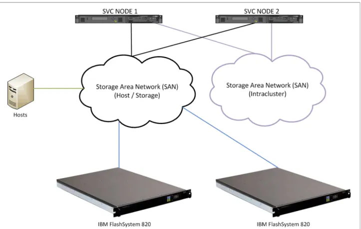
Figure 1-1 shows a conceptual diagram of a storage environment using the SVC. It shows a number of hosts that are connected to a SAN fabric or LAN along with the SVC storage nodes and the storage subsystems that provide capacity to be virtualized. In practical
implementations that have high-availability requirements (most of the target clients for SVC), the SAN fabric “cloud” represents a redundant SAN. A redundant SAN consists of a
fault-tolerant arrangement of two or more counterpart SANs, providing alternate paths for each SAN-attached device. The SVC can be connected to up to four fabrics.
Figure 1-1 Conceptual diagram of SVC and the SAN infrastructure
Both scenarios (using a single network and using two physically separate networks) are supported for Internet Small Computer System Interface (iSCSI)-based and LAN-based access networks to the SVC. Redundant paths to volumes can be provided in both scenarios. For iSCSI-based access, using two networks and separating iSCSI traffic within the networks by using a dedicated virtual local area network (VLAN) for storage traffic prevents any IP
interface, switch, or target port failure from compromising the host servers’ access to the volumes.
A
clustered
system
of SVC nodes that are connected to the same fabric presents logical disks, orvolumes
to the hosts. These volumes are created from managed LUNs ormanaged disks
(MDisks) that are presented to SVC by the storage subsystems and grouped in
storage pools
. Two distinct zones shown in the fabric: A host zone, in which the hosts can see and address the SVC nodes and access volumes
A storage zone, in which the SVC nodes can see and address the MDisks/logical units (LUNs) that are presented by the storage subsystems
Figure 1-2 shows the logical architecture of SVC, illustrating how different storage pools are built grouping MDisks, and how the volumes are created from those storage pools and presented to the hosts through I/O groups (pairs of SVC nodes). In this diagram, Vol2, Vol7, and Vol8 are mirrored volumes, or volumes with two copies, with each copy residing in a different storage pool.
Figure 1-2 Overview of SVC clustered system with relations to the hosts and storage subsystems
Each MDisk in the storage pool is divided into a number of
extents
. The size of the extent is selected by the administrator at the creation time of the storage pool and cannot be changed later. The size of the extent ranges from 16 MB up to 8192 MB. Figure 1-3 on page 7 gives an outline on how a volume is built using the extents that come from a storage pool, depending on the volume type (striped or sequential).Figure 1-3 Volume creation from storage pools
1.1.4 IBM SmartCloud Virtual Storage Center
IBM SmartCloud® Virtual Storage Center (VSC) can help you to achieve enhanced storage efficiency, greater mobility, and stronger control over storage performance and management. The following capabilities are key value enhancers:
Virtualized physical storage resources for improved asset utilization
Easy data mobility across arrays and tiers
Centralized management that offers visibility, control, and automation
SmartCloud Virtual Storage Center helps accelerate time-to-value and reduce significant total cost of ownership by providing:
Insights that offer advanced topology views, metrics for storage configurations, performance, tiered capacity, and customizable IBM Cognos® based reporting
Best practice recommendations that offer guidance for configuration, provisioning, and SAN planning to help ensure optimal setup
Monitoring and reporting that offer performance heat maps, and threshold and fault alerting for high availability
Storage optimization that offers guidance for optimal configuration and enhanced utilization, and data migration recommendations through tiered storage capacity optimization tools
SmartCloud Virtual Storage Center offers both a storage virtualization platform and
capabilities for storage virtualization management. SmartCloud VSC V5.1 delivers to clients, under one licensed software product, the complete set of advanced functions available in IBM Tivoli Storage Productivity Center, all the functions available with the virtualization, remote-mirroring, FlashCopy capabilities of IBM System Storage SVC, and all the capabilities of IBM Tivoli Storage FlashCopy Manager.
This way, SmartCloud VSC is an excellent alternative to have storage virtualization with SVC nodes, complemented by a management platform and data protection, all under a single license. SmartCloud Virtual Storage Center is also referred to as a
Storage Hypervisor
because of its combination of a virtualization platform and a management platform.
1.2 SAN Volume Controller hardware and software updates of
interest to this book
Throughout its lifecycle, SAN Volume Controller has leveraged IBM System x server technology to offer a modular, flexible platform for storage virtualization that can be rapidly adapted in response to changing market demands and evolving client requirements. This “flexible hardware” design allows us to quickly incorporate differentiating features that allow our clients to succeed. As of this writing, there are two significant hardware updates available for the SVC that are of interest:
Feature code AHA7, offering an additional 4-port 8 Gb host bus adapter (HBA)
2145 - SVC Compression Accelerator, RPQ 8S1296, offering an additional 6-core CPU and an additional 24 GB of memory
Additionally, SVC Storage Software version 7.1 offers several feature updates of interest to us in this book:
Second Fibre Channel HBA support
Port masking
Support for Easy Tier with compressed volumes
1.2.1 Hardware updates for SVC
There are two new hardware updates that we mention in this book.
Additional 4-port 8 Gb HBA
This feature adds an additional 4-port 8 Gbps Fibre Channel HBA to improve connectivity options on the SAN Volume Controller engine. The SVC engine comes standard with a 4-port 8 Gbps Fibre Channel HBA. This feature adds a second HBA.
The following example scenarios describe where these additional ports can provide benefits:
Isolation of node-to-node communication, potentially boosting write performance
Isolation of node to IBM FlashSystem communication, allowing for maximum performance
For more information about practical usage scenarios for this additional card, see 2.1, “Usage considerations” on page 42.
This feature code is only supported on 2145-CG8 nodes (both 4-core or 6-core CPU) and requires SVC Storage Software version 7.1 or higher. For more information, refer to
IBM System Storage SAN Volume Controller Storage Engine Fibre Channel host bus adapter feature, IBM United States Hardware Announcement 113-096:
http://www.ibm.com/common/ssi/cgi-bin/ssialias?infotype=AN&subtype=CA&htmlfid=897/ ENUS113-096&appname=USN
Additional CPU and memory
This request for price quotation (RPQ) allows you to add a second, 6-core CPU and an additional 24 GB of memory to a CG8 engine. The standard CG8 engine has a single, 6-core
CPU (type E5645) and 24 GB of memory.1 As discussed in section 4.3.1, “MDisk LUN configuration on IBM FlashSystem 820” on page 111, four of the six standard CPU cores are used for general system processing, while the remaining two are reserved for use by
IBM Real-time Compression (RtC).
When RtC is used on an SVC I/O group, the system surrenders an additional two cores per CPU and 2 GB of memory from each node in the I/O group for use by Real-time
Compression.
This effectively reduces the amount of system CPU resources that are available. To avoid the potential for any impact that this may have, this RPQ has been designed to address this by:
Closely preserving the amount of resources that are available for general system processing, regardless of whether Real-time Compression is in use or not
Increasing the amount of resources available for Real-time Compression
Table 1-1 details the resource allocation differences for CG8 nodes with and without this RPQ, with Real-time Compression in use and not in use.
Table 1-1 Resource allocation for CG8nodes with and without RPQ 8S1296
For more information about this RPQ, contact your local IBM Storage Sales Specialist.
To submit a Solution for Compliance in a Regulated Environment (SCORE) request for this RPQ, see the following site:
http://iprod.tucson.ibm.com/systems/support/storage/ssic/interoperability.wss
1.2.2 New features in SVC Storage Software version 7.1
Three new software updates are mentioned in this book.
Second Fibre Channel HBA support
This new software feature adds support for the additional 4-port 8 Gbps Fibre Channel HBA that is available in feature code AHA7. SVC Storage Software version 7.1 or higher is required to use this new hardware feature code. The software includes GUI and CLI support for configuring and managing this additional card.
Port masking
The addition of more Fibre Channel HBA ports that are introduced with feature code AHA7 allow clients to optimize their SVC configuration by using dedicated ports for certain system functions. However, the addition of these ports necessitates the ability to ensure traffic isolation.
1 Early CG8 nodes shipped with a single quad-core CPU (type E5630). RPQ 8S1296 is only available for six-core CG8 nodes. You can use the lsnodevpd command to determine the type of processor in your node.
Standard 2145-CG8 Node 2145-CG8 Node with RPQ 8S1296
No RtC RtC in Use No RtC RtC in Use
System CPU Cores 4 2 4 4
System Memory 24 GB 22 GB 24 GB 22 GB
RtC CPU Cores 2 4 8 8
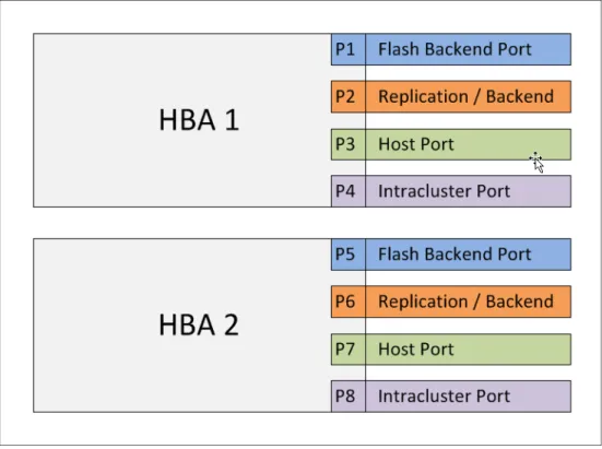
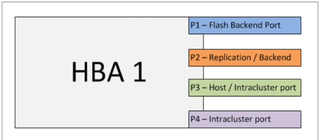
Following are two examples of traffic types that you might want to isolate using port masking:
Local node-to-node communication
Replication traffic
For more information about port masking, see section 2.1, “Usage considerations” on page 42, and 4.2, “Port masking and SAN zoning configuration” on page 108.
Support for Easy Tier with compressed volumes
Easy Tier is a no-charge performance optimization function that automatically migrates “hot” extents belonging to a volume to MDisks that better meet the performance requirements of that extent. The Easy Tier function can be turned on or off at the storage pool level and at the volume.
Real-time Compression is a feature of SVC that addresses all the requirements of primary storage data reduction, including performance, using a purpose-built compression
technology, allowing for data reduction of up to 80%.
In practice, clients have found that their target workloads for these two features have a significant overlap. Before SVC Storage Software version 7.1, the use of these two features was mutually exclusive at the volume level. In version 7.1, the concurrent use of Easy Tier and Real-time Compression is supported on the same volume.
1.3 Introduction to IBM FlashSystem storage systems
IBM FlashSystem storage systems deliver high performance, efficiency, and reliability to various storage environments, helping to address performance issues with the most important applications and infrastructure. These storage systems can either complement or replace traditional hard disk arrays for many business-critical applications that require high performance or low latency. Such applications include online transaction processing (OLTP), business intelligence (BI), online analytical processing (OLAP), virtual desktop infrastructures (VDIs), high-performance computing (HPC), and content delivery solutions (such as cloud storage and video-on-demand).
Known existing flash-based technologies, such as PCIe flash cards, serial-attached SCSI (SAS), or Serial Advanced Technology Attachment (SATA) solid-state drives (SSDs) are traditionally located inside individual servers. Such drives are limited in that they deliver additional performance capability only to the dedicated applications running on the server, and are typically limited in capacity. Hybrid shared storage systems, using both flash and spinning disk technology at the same time, offer the potential to improve performance for a wide range of tasks. However, in products of this type, the internal resources of the system (that is, bus, PCI adapters, and so on) are shared between SSD drives and spinning disks, limiting the performance that can be achieved using flash technology.
As shared data storage devices that are designed around flash technology, IBM FlashSystem storage systems deliver performance beyond that of most traditional arrays, even those that incorporate SSDs or other flash technology. FlashSystem storage systems can also be used as the top tier of storage, alongside traditional arrays in tiered storage architectures, such as SVC or Storwize V7000 storage virtualization platforms using IBM Easy Tier functionality. Additionally, IBM FlashSystem storage systems have sophisticated reliability features such as Variable Stripe Redundant Array of Independent Disks (RAID) that are typically not present on locally attached flash devices.
The IBM FlashSystem portfolio includes shared flash storage systems, SSD devices that are provided in disk storage systems, and server-based flash devices.
For more information, see the IBM FlashSystem storage systems home page:
http://www.ibm.com/systems/storage/flash
1.3.1 IBM FlashSystem storage system portfolio
IBM recently introduced the FlashSystem portfolio of flash-based storage systems. By using flash solid-state storage technology, FlashSystem devices are both cost-effective and high performance, and can be used to accelerate critical business applications.
Two families of the IBM FlashSystem storage systems exist:
IBM FlashSystem 710 and IBM FlashSystem 810 family
IBM FlashSystem 720 and IBM FlashSystem 820 family
IBM FlashSystem 710 and IBM FlashSystem 810
IBM FlashSystem 710 and IBM FlashSystem 810 devices feature Variable Stripe RAID, Active Spare support, and other unique reliability technologies. Connectivity options include four 8 Gbps Fibre Channel (FC) or four 40 Gbps quadruple data rate (QDR) InfiniBand interface ports. FlashSystem 710 and FlashSystem 810 storage systems occupy 1U of standard 19-inch rack space and are available with the following features:
Four 8 Gbps FC or 40 Gbps QDR InfiniBand interface ports
Up to 5 TB of usable single-level cell (SLC) flash storage (6.9 TB raw capacity), or 10 TB of usable enterprise multi-level cell (eMLC) flash storage (13.6 TB raw capacity)
Dual power supplies with batteries to shut down safely in power loss events
For more information about the specifications and features of the IBM FlashSystem 710 and IBM FlashSystem 810 storage systems, refer to the following link:
http://www.ibm.com/systems/storage/flash/710-810/index.html
IBM FlashSystem 720 and IBM FlashSystem 820
IBM FlashSystem 720 and FlashSystem 820 storage systems are external, shared flash solid-state storage devices that provide high performance, density, and efficiency in small integrated rackmount footprints. The FlashSystem 720 and FlashSystem 820 have a unique combination of extremely low latency and high performance that offers clients scalable usable capacity points 5 - 20 TB (fully protected) using either SLC or eMLC flash storage media.
FlashSystem 720 and FlashSystem 820 products also incorporate advanced reliability technology, including 2D Flash RAID and Variable Stripe RAID self-healing data protection:
Four 8 Gbps FC or 40 Gbps QDR InfiniBand interface ports
Up to 10 TB of usable RAID 5 protected SLC flash storage capacity (12.4 TB usable RAID 0, 16.5 TB raw capacity), or 20 TB of usable RAID 5 protected eMLC flash (24.7 TB usable RAID 0, 33.0 TB raw capacity) storage
Dual power supplies with batteries to shut down safely in power loss events
For more information about the specifications and features of the IBM FlashSystem 720 and IBM FlashSystem 820 storage systems, see the following site:
http://www.ibm.com/systems/storage/flash/720-820/index.html
Note: IBM has a rich portfolio of flash-based systems and products. However, for the
purposes of this book, we use the term
IBM FlashSystem storage systems
to refer to the external flash-based systems with Fibre Channel host connectivity only.1.3.2 Differences between IBM FlashSystem families and models
The basic technology and design approach is similar in all FlashSystem storage systems in the portfolio. However, there are some particular differences that should be taken into account when planning and sizing the solution.
Differences between FlashSystem x10 and x20
Table 1-2 briefly describes the key differences between IBM FlashSystem models.
Table 1-2 Key differences between IBM FlashSystem 710/810 and 720/820 storage systems
Differences between FlashSystem 710/720 and 810/820
The main difference between IBM FlashSystem models 710/720 and 810/820 is the flash memory technology that is used to provide storage capacity. For the differences between these two technologies, refer to 1.4.3, “Single-level cell memory” on page 16, and 1.4.4, “Multi-level cell memory” on page 17.
Table 1-3 briefly describes the key differences between IBM FlashSystem 710/720 and 810/820 models.
Table 1-3 Key differences between IBM FlashSystem 710/720 and 810/820 storage systems
Usage considerations for IBM FlashSystem storage systems
Selection of the appropriate storage system from any vendor always involves a compromise between the price and the performance. For flash-based systems, reliability must also be considered.
There are two groups of flash storage systems in the IBM portfolio:
FlashSystem 720/820 with 2D Flash RAID data protection
FlashSystem 710/810 without 2D Flash RAID data protection
Selection of the appropriate system depends on consideration of the following factors:
Availability
Flash memory technology
Initial and maximum storage capacity
Price per TB
Price per TB and flash memory technology should be considered during the initial solution design or after a detailed examination of the workload characteristics. Selection between performance and availability is not an obvious choice.
IBM FlashSystem 710/810 IBM FlashSystem 720/820
1D RAID across flash chips 2D RAID across flash chips and flash modules
Incremental capacities Incremental capacities
No flash hot-swap Flash module hot-swap
5 TB/10 TB maximum capacity 10 TB/20 TB maximum capacity
IBM FlashSystem 710/720 IBM FlashSystem 810/820
Figure 1-4 provides comparative performance and availability information for IBM FlashSystems to assist in this process.
Figure 1-4 Quadrant chart detailing comparative performance and availability for IBM FlashSystems
Figure 1-4 shows the positioning of the flash systems in terms of availability and performance, allowing you to select between the most reliable and performing systems.
In addition, we offer the following criteria to be considered for selecting IBM FlashSystem 720 and 820 storage systems:
If the environment is not known completely, or the workload amount and access patterns are not clearly identified, consider using IBM FlashSystem 720/820 first. This provides a balance between availability and performance.
2D Flash RAID data protection makes these systems capable of providing long-term data storage for frequently accessed and changing data.
IBM SVC Easy Tier environments are ideal candidates for these systems.
Implementation of IBM FlashSystems 720/820 into an existing IBM SVC with HDD-based disk systems environments will be more beneficial from an extent migration and data relocation point of view.
Likewise, we offer the following criteria to be considered for selecting IBM FlashSystem 710 and 810 storage systems:
IBM FlashSystem 710/810 should be used in environments where mirroring or protection is provided by another layer in the environment.
These systems can be used also to provide low latency for the following applications: – HPC data processing environments require the lowest latency possible. This is often
because the tasks are single-threaded and meant to be processed sequentially. Data protection can be provided by traditional methods of making regular backups to keep the intermediate results of the processing. Data sources can be kept separately on Tier 1 and Tier 2 storage systems.
– OLTP database environments, which require requests to specific areas of the data to be serviced with the lowest latency. FlashSystems can be used to store and service that data during peak periods of activity, or to provide the Tier 0 storage level to store the hottest data. Additional data protection can be provided by the Volume Mirroring option of SVC, or the mechanisms of the database software.
– Video transcoding, processing, and editing tasks can also benefit from the ability of the IBM FlashSystem 710/810 to provide low latency I/O. This can reduce the processing
and transcoding times and reduce the time of the delivery of the content. Data protection may be provided using various methods. However, FlashSystems typically play the role of the temporary storage in this use case. If any error occurs, the data will be replaced with the original after the systems are fixed.
– Virtual Desktop Infrastructures, utilizing multiple access to single images, can
experience significant benefit from IBM FlashSystems 710/810, which can allow them to serve more requests with lower latency during peak times of the workloads.
1.4 Introduction to flash solid-state technology
SSDs have evolved from the small storage capacity in mobile devices and selected computer systems, where they are used to provide low-power consumption and resist rough handling, to an enterprise class server and external storage, where SSDs provide high data transfer rates and extremely low access latency. Because flash technology is the key component of SSDs, it is important to understand it and know its advantages and limitations.
Flash memory is an electronic non-volatile storage device, which can be electronically programmed and reprogrammed. Two predominant types of flash memory are currently available in the market of storage technologies for portable devices and high-speed low latency access for servers and storage systems:
NOR
2flash memory
andNAND flash
memory
. Because NAND flash memory provides higher density of storage, it has been wider used for storage devices like SSDs or consumer USB storage drives.NOR flash has been used mostly for storing firmware and microcode in devices that require rapid booting and faster waking from the power-off state. The internal architecture of NOR flash enables short read times, which are critical for the random access nature of
microprocessor instructions. This type of flash memory is ideal for lower-density, high-speed, mostly read-only applications, often referred to as
code-storage applications
.NAND flash is an alternative to NOR flash. Its architecture’s high storage density and smaller cell size enable faster write and erase performance by programming blocks of data. NAND flash is ideal for low-cost, high-density, high-speed program/erase applications, often referred to as
data-storage applications
. With the rapid growth in technology and the increasing demand to store and manage data in more devices. NAND memory, with its simple erase and write capability, has become more popular than NOR memory. Technology advancements have significantly decreased the cost of NAND memory and made it the popular solution for the flash-based storage devices.The most significant technological difference between these two types of memory is the way that the data is addressed. NOR flash is addressed byte by byte, whereas NAND is
addressed by page number. Pages are a power of two, commonly 512 or 2048 bytes, and optimized for reading and writing a page at a time. Erases also take place at the byte level for NOR memory, where NAND has to erase a whole block at one time, typically of 64 pages in size.
All future references to flash memory-based devices and systems in this book should be considered as NAND-based.
2 Names NOR and NAND stand for the “Not-OR” and “Not-AND” logical operations and the appropriate types of the logical gates that this type of memory is made of. For more information about the technology used, refer to the following article: Pavan, Paolo; Bez, Roberto; Olivo, Piero; Zononi, Enrico (1997). “Flash Memory Cells – An Overview”. Proceedings of the IEEE 85 (8) (1997). pp. 1248 – 1271. doi:10.1109/5.622505.
1.4.1 Types of flash memory used in IBM FlashSystems
The two most commonly available types of flash memory that is used in most storage systems on the market today are:
SLC
andMLC flash memory
. Before explaining each technology, we first detail how the flash cell operates.Cell operation
Each cell consists of a transistor with an additional “floating” gate, which can store the electrons.3 The charge of the electrons applied to the gate allows the cell to be programmed to state 1 or 0, and the charge kept in the floating gate layer maintains that state. Because the “floating” gate is electrically isolated by an oxide layer, any electrons placed on it are trapped there, making flash memory non-volatile. Flash memory works by adding (charging) or removing (uncharging) electrons to or from a floating gate. For the internal structure of the transistor, refer to Figure 1-5.
Figure 1-5 Memory cell transistor (simplified schematics)
Reading operation
For reading, the gate is electronically disconnected to measure the voltage levels between the drain and the source of the transistor. When electrons are present on the floating gate, current cannot flow through the transistor, and the bit state is 0. This is the normal state for a floating gate. When electrons are removed from the floating gate, current is allowed to flow, and the bit state becomes 1. A bit’s 0 or 1 state depends upon whether or not the floating gate is charged or uncharged.
Write and erase operations
Writing is changing the state of the cell from one state to another. In terms of the transistor, that means applying or removing the charge of the gate. This is done by applying a
programming voltage (which is quite high) to the gate and grounding the channel, setting up an electric field such that electrons are attracted to the surface of the channel. Some of these electrons have enough energy to tunnel through the insulating layer. These electrons are captured by the floating gate. Erasing is the opposite operation, where the gate is grounded and with programming voltage applied to the channel to create an electric field with the opposite polarity. This attracts electrons back to the channel, many of which will have enough energy to cross the insulating barrier.
1.4.2 Unique characteristics
Two important characteristics of flash technology present challenges regarding designing storage products.
Disturb errors
Erasing (writing) the cell cannot be done on a one-by-one basis, due to the power of the electric fields applied to the gate. The size of the elements used in the cell is comparable to the length of the wave in the electrical field, so it may likely disturb the nearest cells and make them become reprogrammed also. To overcome this limitation, memory is written in terms of pages, typically 1 KB- 4 KB size. Erasing occurs at the block level, which is typically 32 - 128 pages.
Limited write/erase cycles
Due to the nature of the materials used and the methods of programming and erasing the cell, electrons must have enough energy to be able to cross the insulating oxide. Some of them have enough energy to cross the barrier that is insulating the gate and the transistor channel, but not enough energy to return. This forces them to reside in the insulating oxide. Over time, as more write/erase cycles pass through the cell, more electrons become trapped, increasing the charge of the gate itself. Eventually, the state between charged and uncharged becomes less easily detectable, rendering the cell useless. This process is commonly called
memory aging
orwearing-out
. See Figure 1-7 on page 17 for reference.1.4.3 Single-level cell memory
Single-level cell (SLC) memory operates similarly to the process described above. It is capable of storing one bit at a time, and the cell can be in only one of two possible states: programmed or erased. The voltage value measured on the cell depends entirely on the amount of the charge applied to the floating gate. To determine the state of the cell, the measured voltage value is compared to a reference voltage value. If the measured voltage is within a specific range that is higher than the reference voltage, the cell state is
programmed
. If the measured voltage is within a specific range that is lower than the reference voltage, the cell state iserased
. Figure 1-6 shows the voltage reference for SLC.Table 1-4 shows the possible states of the memory cell.
Table 1-4 SLC levels
As the number of the write/erase operations performed on the cell increases, the difference between
programmed
anderased
measured voltages gets smaller, as shown in Figure 1-7. As the values approach each other, it becomes difficult to determine the state of the cell. This happens because accumulated charge at the floating gate prevents the complete cut-off of the current in the cell.Figure 1-7 Potential overlapped voltage levels of SLC
1.4.4 Multi-level cell memory
Multi-level cell (MLC) memory4 can have more than two threshold levels, and as a result, store more than one bit at a time. Typically, they store two or three bits. After erasure, the cell is in one of two erased states. By changing the charge at the floating gate, the cell can be programmed from fully erased to partially erased, to partially programmed, and, finally, to fully programmed. This is done in the same manner as described earlier for gradually
programming the SLC cell, by applying write pulses, then sensing the amount of charge to ensure that the cell was properly programmed. See Table 1-5 for the MLC levels.
Table 1-5 MLC levels
Value State
0 Programmed
1 Erased
4 In this book, references to multi-level cell memory refer to both multi-level cell and enterprise multi-level cell memory. Value State 00 Fully programmed 01 Partially programmed 10 Partially erased 11 Fully erased
As shown in Figure 1-8, the gaps between the different states are closer than as in SLC. As a result, the measured voltages can begin to overlap sooner, reducing the usable life of the cell. In other terms, this can be thought of as a lower “signal-to-noise ratio” for MLC than for SLC, requiring better error correction codes and mechanisms.
Figure 1-8 Voltage reference for MLC
The ability of MLC to have multiple states allows it to store more data per cell, but the amount of write/erase operations increases accordingly. This leads to shorter usable life of MLC flash as compared to SLC flash. For information about estimating the lifetime of flash, see 1.4.6, “Flash memory lifetime” on page 21.
1.4.5 Solid-state drive architecture
SLC and MLC memory is a complex technology that should be properly managed to ensure that it provides all its potential benefits. Solid-state drives are the most popular
implementation format of this technology in the enterprise storage space. Figure 1-9 on page 19 demonstrates the common architecture of the SSD.
Note: There are MLC flash chips that can store three or four bits per cell. For the purposes
Figure 1-9 Architecture of the solid-state drive
Following are basic components of the SSD:
Flash memory
Disk controller
Interface controller
Depending on the manufacturer, there might be other components included in the SSD, such as additional flash memory controllers, error correction code (ECC) controllers, and additional blocks in the disk controller.
Flash memory
Flash memory is the basic component of the SSD that provides the data storage. Depending on the disk purpose, the memory can be SLC or MLC. The amount of raw memory capacity in the SSD is usually several percent more than the usable capacity. This additional memory capacity is used for data placement, one of the key techniques used to address wear-leveling and increase the lifetime of the SSD. Flash memory components also include all necessary communication and ECC controllers.
Interface controller
The interface controller is responsible for presenting the SSD as a SATA, SAS, or FC drive in the operating system or external disk system. It also includes all necessary communications, connectors, and controllers.
Disk controller
The disk controller is a key component of the SSD architecture, and commonly the technology that differentiates the SSD drives of various manufactures. In general, the disk controller is the System-on-Chip (or several chips) representing the processor, firmware, random access memory (RAM), flash translation layer (FTL), wear-leveling algorithms, ECC controllers, and possibly, other components for encryption, data deduplication, additional aging prevention, and so on. The disk controller provides the following functionality:
Flash translation layer function
Garbage collection function
Wear-leveling function
Flash translation layer
The flash translation layer emulates a standard block device by exposing only read/write operations to the upper software layers. It performs the virtual-to-physical address
translations and hides the erase-before-write characteristics of flash memory. The FTL also emulates the over-write operation with out-of-place updates. In out-of-place updates, the physical location of data is changed on every write request, and the FTL maintains a mapping table between the logical sector and physical location. The address mapping table is usually stored in a small piece of RAM. According to the size of the mapping unit used, FTL schemes are classified as block mapping, page mapping, and hybrid mapping5. The flash translation layer also provides garbage collection and wear-leveling capabilities that are vital to the performance and reliability of flash SSD.
Garbage collection
Garbage collection (GC) is a process that erases dirty blocks and recycles their obsolete pages. If a block that is selected for erasure has some valid pages, those pages are migrated to other blocks before erasing the block. Because garbage collection involves time-consuming erase operations and numerous internal reads and writes, an ongoing GC process can stall incoming user requests until it completes. As a consequence of the queuing delay, the performance of flash SSD can be significantly degraded by 20%6. Various GC mechanisms have been proposed to minimize the garbage collection overhead. In particular, much effort has been focused on reducing the total amount of copied data from the erased blocks, because moving valid data from erased blocks to new blocks represents a large portion of the total execution time of a garbage collection process. The most common way to achieve this goal is to separate data based on update frequency, so that the number of obsolete blocks (that is, blocks that have no valid data) and almost-obsolete blocks (that is, blocks that have very little valid data) can be increased. Recycling obsolete or almost-obsolete blocks can substantially reduce overhead.7
Wear-leveling
The purpose of wear-leveling algorithms is to evenly distribute block erasures over the flash memory, and thus enhance its endurance. Wear-leveling algorithms can be classified into dynamic wear-leveling and static wear-leveling.
Dynamic wear-leveling
The performance of dynamic wear-leveling depends on hot and cold data identification. Cold data always stays in the same blocks, regardless of whether updates to hot data wear out 5 Covering these techniques is out of the scope of this book. For more information, refer to the following paper:
Hot/Cold Clustering for Page Mapping in NAND Flash Memory, Ilhoon Shin, IEEE Transactions on Consumer Electronics, Vol. 57, No. 4, November 2011.
6 Estimated value, might vary.
7 For more information about garbage collection techniques, refer to this paper: Making Garbage Collection Wear Conscious for Flash SSD, Jonathan Tjioe, Andrés Blanco, Tao Xie, Yiming Ouyang; 2012 IEEE 7th International Conference on Networking, Architecture, and Storage.