Precision Engineering of Micrometer and Nanometer
Droplets for Ultrasound Imaging and Therapy
Thomas D. Martz
A dissertation submitted to the faculty of the University of North Carolina at Chapel Hill and North Carolina State University at Raleigh in partial fulfillment of the require-ments for the degree of Doctor of Philosophy in the Joint Department of Biomedical Engineering.
Chapel Hill 2011
Approved by:
Paul A. Dayton, Ph.D.
Robert Dennis, Ph.D.
c
ABSTRACT
THOMAS D. MARTZ: Precision Engineering of Micrometer and Nanometer Droplets for Ultrasound Imaging and Therapy.
(Under the direction of Paul A. Dayton, Ph.D.)
The medical community has interest in improving techniques such as occlusion, therapeutics and imaging through the use of liquid perfluorocarbon droplets. The abil-ity to create a monodispersed population of liquid perfluorocarbon droplets would have the added advantage of uniform acoustic activation parameters. A microfluidic device with a flow-focusing orifice allowed for uniform production of perfluoropentane droplets in the micron and submicron diameter range. These droplets are able to be stored for over two weeks while retaining distribution characteristics. The observed activation of the droplets shows the acoustic threshold as a function of droplet diameter with little variability. Results showed that microfluidic technology with a pressure controlled flow regulator will allow for greater manufacturing control of phase-change perfluorocarbons in the micron and sub-micron size range for acoustic droplet vaporization applications.
ACKNOWLEDGMENTS
Contents
List of Figures . . . viii
List of Tables . . . x
1 Specific Aims . . . 1
1.1 Aim 1: Microfluidic Device . . . 2
1.2 Aim 2: Input Control . . . 2
1.3 Aim 3: Uniform/Monodispersed . . . 3
1.4 Aim 4: Acoustic Droplet Vaporization . . . 3
1.5 Aim 5: Stability . . . 3
2 Significance . . . 4
2.1 Aim 1: Microfluidic Device . . . 4
2.2 Aim 2: Input Control . . . 5
2.3 Aim 3: Uniform/Monodispersed . . . 5
2.4 Aim 4: Acoustic Droplet Vaporization . . . 6
2.5 Aim 5: Stability . . . 6
3 Innovation . . . 7
3.1 Aim 1: Microfluidic Device . . . 7
3.2 Aim 2: Input Control . . . 8
3.3 Aim 3: Uniform/Monodispersed . . . 9
3.4 Aim 4: Acoustic Droplet Vaporization . . . 9
3.5 Aim 5: Stability . . . 10
4 Materials & Methods . . . 11
4.1 Materials Database . . . 12
4.2 Microfluidic Device Fabrication . . . 13
4.3 Reagent Preparation . . . 14
4.4 Reagent Flow Control . . . 15
4.5 Microfluidic Droplet Production . . . 16
4.6 Sample Collection . . . 17
4.7 Acoustic Droplet Vaporization . . . 18
4.8 Sample Processing . . . 19
5 Results . . . 21
5.1 Aim 1: Microfluidic Device . . . 21
5.2 Aim 2: Input Control . . . 23
5.3 Aim 3: Uniform/Monodispersed . . . 24
5.4 Aim 4: Acoustic Droplet Vaporization . . . 26
5.5 Aim 5: Stability . . . 27
6 Results . . . 28
7 Conclusion . . . 30
8 Publications . . . 31
8.1 Ultrasound in Medicine & Biology . . . 32
8.1.1 Abstract . . . 32
8.1.2 Introduction . . . 33
8.1.4 Results . . . 37
8.1.5 Discussion . . . 42
8.1.6 Conclusion . . . 42
8.1.7 Acknowledgements . . . 43
8.2 Lab on a Chip Publication . . . 44
8.2.1 Abstract . . . 44
8.2.2 Introduction . . . 45
8.2.3 Materials and methods . . . 48
8.2.4 Results and discussion . . . 52
8.2.5 Conclusion . . . 61
8.2.6 Acknowledgements . . . 62
8.3 Small Publication . . . 63
8.3.1 Introduction, Results, Discussion & Conclusion . . . 63
8.3.2 Experimental Section . . . 68
8.3.3 Acknowledgements . . . 69
Bibliography . . . 71
List of Figures
4.1 Microfluidic Device Layout . . . 14
4.2 Syringe Pump System and the Pressure Control Flow System . . . 16
4.3 Microfluidic Device Testing Setup . . . 17
4.4 Microfluidic Droplet Collection Methods . . . 18
4.5 Acoustic Droplet Vaporization Testing Setup . . . 19
5.1 Microfluidic Device Filter System . . . 22
5.2 “V” Shape Collection System . . . 23
5.3 Consistent Monodispersed Droplet Production . . . 24
5.4 Initial Coalescence . . . 25
5.5 Initial Population Distributions . . . 25
5.6 Uniform Sub-micron Droplet Production . . . 26
5.7 Acoustic Droplet Vaporization . . . 27
5.8 Stability of Droplets over 2 Weeks . . . 27
8.1 Microfluidic Droplet Production . . . 38
8.2 Acoustic Pressure vs. Diameter . . . 40
8.3 Population Analysis . . . 41
8.4 Liquid to Gas Transition . . . 46
8.5 Device Geometry . . . 48
8.6 Droplet Formation Regimes . . . 55
8.7 Production Characteristics . . . 56
8.8 Dripping Regimes . . . 57
8.10 Production Rates . . . 59
8.11 Stability Analysis . . . 60
8.12 Thermal Vaporization . . . 61
8.13 Nano Tipstreaming . . . 66
8.14 Nanosizer Population . . . 67
8.15 TEM Image . . . 67
List of Tables
4.1 Materials Used During Research . . . 12
8.1 Polydispersity Data . . . 39
8.2 Production Rates . . . 41
Chapter 1
Specific Aims
In the 1990s, the US Department of Defense supported programs that included the creation of field-deployable microfluidic devices for detecting biological threats. Since that time, the microfluidic process has evolved and rapidly advanced for use in a variety of applications(Whitesides, 2006). Microfluidic devices were initially made from glass and silicon. However, it was soon discovered that these materials did not encompass all of the material properties that were needed for success in microfluidics. Due to its near optical transparency and soft flexible elastomer, polydimethylsiloxane or PDMS became the most widely used material for microfluidic applications. Also, a notable advancement in the field, soft lithography, has made it possible to go from design to production in less than two days(Whitesides, 2006). With the evolvement of microfluidics, the ability to create controlled bubbles (Garstecki et al., 2004) and droplets (Whitesides, 2006) began to develop. For example, a flow-focusing device with a small pinch off area has been shown to create uniform droplets or microbubble samples (Garstecki et al., 2004). The evolution of microfluidics has given us the opportunity to create uniform droplets for applications such as contrast enhanced ultrasonography (Kripfgans et al., 2002; Marsh et al., 2007), vessel occlusion (Kripfgans et al., 2002; Kripfgans et al., 2005; Zhang et al., 2010), drug delivery (Rapoport et al., 2009b), or multi-purpose systems (Fabiilli et al., 2010b). These droplets can be fabricated in the micron and sub-micron diameter range. To the knowledge of the author, the uniform fabrication of sub-micron droplets or sub-micron acoustic droplet vaporization (ADV) agents, without a resulting large diameter droplet, is novel.
(PFP) was used exclusively in this research due to its boiling point (29°C) being close to physiological temperatures. At this boiling point, the introduction of an acoustic pressure from an ultrasound transducer, can induce a liquid to gas phase-change. An ultrasonic induced phase change of ADV vehicles may have many different applications including, but not limited to, controlled drug release , controlled vessel occlusion, and an increase in contrast enhancement. Prior to our research , the fundamental problems associated with ADV agent fabrication methods included vagueness in the activation threshold and the uncertainty of its use in ultrasound contrast enhanced applications based on phase-change bubble size. To address the needs of the medical ultrasonics field, we propose the following hypothesis:
Hypothesis: The development of size-controlled micron and sub-micron droplets for controlled vessel occlusion, drug delivery vehicles, and ultrasound contrast agents can be created and tested using rapid prototyping microfluidic devices .
To test this hypothesis, we propose the following Specific Aims:
1.1
Aim 1: Design a versatile microfluidic device to
create a spectrum of droplet sizes with different
materials.
• Vary the diameters of channels and orifices to maximize the efficiency of the microfluidic device. (UCI)
• Implement a notched output collection mechanism for easy collection.
1.2
Aim 2: Precisely control the input of the target
reagents into the microfluidic device.
1.3
Aim 3: Create uniform/monodisperse micron and
sub-micron samples.
• Introduce a pressure control flow system to improve the control of vehicle diam-eters.
• Demonstrate that the pressure control flow system can be used for “nano tip-streaming” and the production of sub-micron vehicles.
1.4
Aim 4: Initiate acoustic droplet vaporization to
demonstrate controlled uniform activation and
over-all expansion.
• Create a system in which an ultrasound transducer is aligned with a microscope objective and the sample to visually show and record ADV.
• Incrementally increase the pressure of the ultrasound transducer to reach the ADV threshold.
• Characterize a variety of sizes and compositions to determine the droplet vapor-ization threshold of a given diameter droplet.
1.5
Aim 5: Show that the vehicles will maintain
sta-bility over time.
• Improved the lipid formulation to reduce coalescence and thus improve the longevity of the sample.
• Test the samples over a two week period to show that the vehicle population stayed uniform.
Chapter 2
Significance
2.1
Aim 1: Design a versatile microfluidic device to
create a spectrum of droplet sizes with different
materials.
“This research was a collaboration between UNC and UCI. Roger Shih and David Bardin were the main contributors in updating device designs and microfluidic wafer fabrication methods.”
A versatile microfluidic device created with a rapid prototyping procedure will allow for a range of parameters to be tested cheaply and quickly. Other types of vehicle production methods incorporate a variety of materials that may take hours to complete. During that time, it is difficult to watch the production of the vehicles and subsequently control the vehicle size or population. Thus, a system needed to be created that would allow for no excess materials to be used, a real-time means of visualizing production, and the ability to alter the vehicle population in real time. A microfluidic device allows only the droplet materials to be introduced into the system. It is also optically transparent for real-time production visualization and minute changes to the input system of the device will allow for vehicle population control.
of collection. Cutting a wedge at the end of the sample solved the pressure gradient problem and it made collection easier. The wedge design did not hamper production of the device and the capillary forces of the lipid and vessels on the PDMS allowed for easy collection without having to alter the microscope setup.
2.2
Aim 2: Precisely control the input of the target
reagents into the microfluidic device.
The input process of the reagents into the microfluidic device is directly related to the quality of the sample. Using syringe pumps, there may be a 10% variation in the mean diameter of the output sample (Korczyk et al., 2010). The large variations exacerbate the problems when samples are less than 20 µm in diameter. This amount of variation makes it difficult to control the population over a long enough time frame to produce a viable sample. Thus, a more sustainable input process is needed. It was found that using a pressure vessel with a precision regulator substantially decreased the amount of variation from the mean. This was a large enough improvement to create a sample, but the added advantage was that a sample could be altered from 20µm to 5µm in a matter of seconds and remain stable.
2.3
Aim 3: Create uniform/monodisperse micron and
sub-micron samples.
Acoustic droplet vaporization is commonly shown with a polydispersed sample (Fabiilli et al., 2010b; Rapoport et al., 2010). This creates a variance in the acous-tic threshold based on the size of the droplet population. If the distribution is wide, then a much higher acoustic pressure is needed to activate the population compared to a uniform sample. Also, there is the added complexity that a large droplet that is con-verted to a bubble with a low acoustic pressure could influence the remaining droplets’ acoustic threshold creating further uncertainty. Microfluidics were introduced into the study in order to tailor the size distribution to a low polydispersity index. This paired with the pressure control flow system creates uniformity in samples ranging from 800 nm to 25µm.
2.4
Aim 4: Initiate acoustic droplet vaporization to
demonstrate controlled uniform activation and
over-all expansion.
PFP droplets have been shown to be slightly echogenic (Kripfgans et al., 2002; Marsh et al., 2007) but a PFP gas bubble has shown to be highly echogenic within a given system. The samples would not be useful unless they were susceptible to ADV. The samples created were able to be converted to a bubble with a size-dependent acoustic pressure. After droplets were activated via vaporization, the echogenicity of the resulting bubbles would allow for applications such as perfusion mapping. Droplet vaporization also makes drug delivery possible as this allows the drug to be housed within the droplet shell protected from its surroundings or coated and attached to the outside of the shell. Upon activation, the drug would be released at site-specific targets to reduce systemic toxicity. Embolotherapy is also possible as the theoretic expansion rate of the droplet is approximately 6 times the initial diameter. Reducing the blood flow of a site-specific area to a high degree could lead to ischemic necrosis (Kripfgans et al., 2005). There have also been cases where occlusion is paired with drug delivery in the effort to increase the residence time of the chemotherapeutic in the target area.
2.5
Aim 5: Show that the vehicles will maintain
sta-bility over time.
Chapter 3
Innovation
3.1
Aim 1. Design a versatile microfluidic device to
create a spectrum of droplet sizes with different
materials.
“This research was a collaboration between UNC and UCI. Roger Shih and David Bardin were the main contributors in updating device designs and microfluidic wafer fabrication methods.”
With the creation of the initial microfluidic device, it became possible to go from design to use in less than two days (Whitesides, 2006). Also, with the addition of the flow focusing device, two or more materials could be introduced into a flow-focusing device to create a variety of samples including multi-layer vehicles (Hettiarachchi et al., 2009), ADV agents (Martz et al., 2011; Sheeran, 2011; Sheeran et al., 2011b; Sheeran et al., 2011a), and Janus particles (Malloggi et al., 2010). The innovation of the mi-crofluidic device is in the ability to pattern a 6 micron-orifice to allow for balance in production between sub-micron sizes and micron sizes. Another improvement is the addition of a complex filtering system, which stops the device from clogging. In normal circumstances, the fabrication technique can produce objects that are larger than 6 microns, which halted production of droplets. The filtering system evolved over the duration of this research to allow for upwards of 60 psi to be placed on the reagents to induce flow without the fear of clogging.
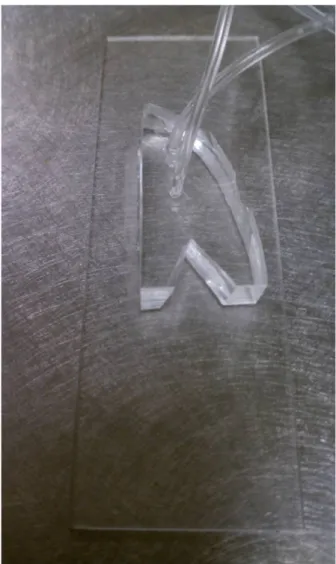
in the production of the droplets leading to samples with a nonuniform distribution. In an attempt to stabilize production, Tygon tubing was placed into the output hole to allow the material to flow into a collection vessel. Unfortunately, droplets sink in a lipid medium and in our method, the droplets were required to go up a slight slope before they could be collected in the vessel. Therefore, the droplets had to build up before moving into the collection vessel, which ultimately led to the previously described pressure gradient. The innovation came with the introduction of a “V” shaped slice in the output of the device where capillary forces act at the PDMS and glass interface to allow for easy collection of the droplets with minor lipid waste.
3.2
Aim 2. Precisely control the input of the target
reagents into the microfluidic device.
Initially, to create multi-layered acoustically active liposomes, four syringe pumps were used for the introduction of reagents. ADV agent research required just two materials, thus we were able to reduce the overall number of syringe pumps to two. Syringe pumps were used as a controllable method for the introduction of the reagents into the microfluidic device due to their ability to maintain hysteresis over a duration of time when the flow rate was changed. However, there was play between the syringe pump and the syringe holding the reagent, the use of a plastic syringe induced flexibility to the chamber complicating the fluidity of the reagent flow, and the syringe pumps did not allow for precise control of the reagent flow that is required to create uniform ADV agents. These issues led to the initiation of a new method for introducing the reagents.
3.3
Aim 3: Create uniform/monodisperse micron and
sub-micron samples.
Initial microfluidic designs utilized an orifice larger than 10 microns. This prevented many of the smaller size samples from being produced due to geometric constraints and the inability to control the flow of the reagents precisely. The innovation of a smaller orifice (6 microns patterned), along with the ability to precisely control the flow of reagents with a pressure vessel, has allowed the effortless production of monodisperse micron sized droplets and the uniform production of sub-micron droplets.
Droplets were created with the use of syringe pumps during the initial studies of this research. This required 100% focus on the device screen to ensure that the droplets did not vary and the uniformity of the sample was not compromised. The innovation of the pressure control flow system to create the uniform samples was the breakthrough that was needed for stable sample creation. With the new pressure control flow system, there is an instant update of droplet size based on the input pressures, the ability to perform nano tip-streaming to produce sub-micron droplets, and the ability to leave the system for hours to produce bulk samples without the fear of variation from the initial droplet diameter. According to a recent literature search, this microfluidic device is the first to create sub-micron droplets with the capability to achieve ∼300nm.
3.4
Aim 4: Initiate acoustic droplet vaporization to
demonstrate controlled activation and overall
ex-pansion.
Initially, the fabricated droplets coalesced over time. Thus, it would take less pres-sure to activate the droplets, thereby disrupting the actual activation threshold of the correct size droplets. This was also compounded with the initial problems of droplet collection, which resulted in an increase in droplet coalescence and a wider distribu-tion of droplet diameters. The innovadistribu-tion was a joint effort between an improved lipid formulation, pressure control flow system, and “V” collection method. These allowed for uniform sub-micron and micron droplets to be produced consistently over time to produce a viable sample without coalescence of resulting droplets, and thus providing an easy collection for implementation into the ultrasound testing apparatus.
3.5
Aim 5: Show that the vehicles will maintain
sta-bility over time.
Chapter 4
4.1
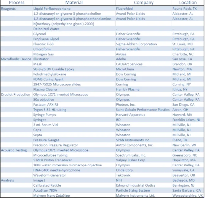
Materials Database
4.2
Microfluidic Device Fabrication
“This research was a collaboration between UNC and UCI. Roger Shih and David Bardin were the main contributors in updating device designs and microfluidic wafer fabrication methods.”
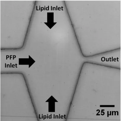
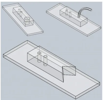
Initial flow-focusing channel designs were created in Adobe Illustrator. The basic layout of the design is pictured in figure 4.1. There are two input holes located on the device with one larger output hole. The design strategy surrounding the flow focusing device is that the outside input hole (lipid) branches to a “T” as illustrated. This “T” branching is brought around the second input hole (PFP) to create a sandwich of lipid/PFP/lipid. This sandwich is located at the flow-focusing region in a pinched orifice that was patterned to be approximately 6 µm. After the orifice, there is an arrow shaped output channel that leads to the output orifice.
The design in Adobe Illustrator was printed at 20,000 dpi by CAD/Art Service and subsequently used as the mask for the silicon wafer. This silicon wafer was first oxidized with the use of a plasma cleaner and spin-coated with a UV curable photoresist. The printed mask was then aligned to the wafer using alignment markers.The wafer was exposed to UV light to develop the channel patterns for use as a negative for device production. The negatively patterned device was then secured in a Petri dish.
Polydimethylsiloxane (PDMS) and a curing agent were placed into a measuring cup in a 10:1 ratio. These materials were mixed resulting in a thick solution containing many small bubbles. The entire contents were then poured over the silicon wafer in the Petri dish. The thickness of the device was a minimum of 1 cm. The Petri dish was then transferred to a vacuum for at least 3 hours to remove any bubbles. A light nitrogen blast helped to remove any residual bubbles that remained in the device area. Lastly, the Petri dish was placed in an oven at 60°C for a minimum of 5 hours to complete the PDMS curing process.
The remaining steps for microfluidic device production were performed in a laminar flow hood. To assist in the removal process, the devices were cut from the PDMS when the PDMS was still warm from the oven. A syringe was used to create a circular cut in the PDMS just inside the outside diameter of the silicon wafer. The circular piece of PDMS was then removed and a razor blade was then used to separate the individual devices.
Individual devices remained inverted in the hood at all times to avoid dust or contaminants. A blunt tip needle was used to remove the PDMS located over the two
input hole regions approximately the size of the Tygon tubing. A razor blade was then used to cut a triangle shape that extends off the device at the output location. The surface and holes were cleaned out with ethyl alcohol and dried with a nitrogen gun. Then, a glass slide was cleaned with ethyl alcohol dried with a nitrogen gun. Care was taken to ensure that there was no residue or debris on the glass slide, which would potentially lead to device failure. The microfluidic channels and glass slide were then placed in a plasma cleaner on high at 500 millitorr for 3 minutes. The microfluidic channels and glass were immediately joined together and held together for at least 30 seconds to ensure a secure bond. Finally, the device channels were filled with DI water and sealed with a piece of scotch tape.
Figure 4.1: Microfluidic Device Layout
4.3
Reagent Preparation
1,2-distearoyl-snglycero-3-phosphocholine (DSPC) and 1,2-distearoyl-sn-glycero-3-phosphoethanolamine-N[methoxy-(polyethylene glycol)-2000] (DSPE-PEG2000). The chloroform was subsequently evap-orated with the use of a nitrogen gun. For the two lipid compositions used in this research, DI water was added as the base for the lipid solutions. The first lipid com-position included the addition of 50 mL of DI water and was sonicated for 20 minutes. After this, 47 mL of DI water was added along with 2 mL of glycerol, 1 mL of propy-lene glycol, and 10 mL of pluronic F-68 surfactant. Finally, this was vortex mixed for 1 minute and sonicated for 10 minutes. This was then used as the lipid reagent for droplet production. The second lipid composition was created with the base ratio as previously stated. 1 mL of the lipid composition was added to 1 mL of glycerol, and 1 mL of pluronic F-68. This solution was then lightly vortex mixed until the appear-ance of a homogeneous solution. This was then used as the lipid reagent for droplet production.
4.4
Reagent Flow Control
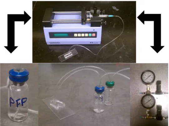
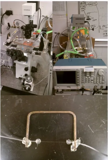
Initial studies were performed with the use of two syringe pumps. These pumps were placed on stages to ensure that the syringe height was located at the height of the microfluidic device. A 5 mL syringe was used as the lipid container and the PFP was housed in a 3 mL syringe. The syringes had a needle at the output that was connected to Tygon tubing, which ran to the microfluidic device inputs. Pressure vessels were used for the remainder of the research due to our need to precisely control the fluid flow. 3 mL of PFP were placed in a 3 mL serum vial. This vial was then capped. Also, 3 mL of lipid reagent was placed in a 3 mL serum vial. This vial was also capped. The septa that were used to cap the vials had two holes placed in them that were slightly smaller than that of the Tygon tubing. A strand of Tygon tubing was placed in each hole. One strand in the headspace of the vial went to a precision pressure controller. This pressure controller was also connected to a pressure gauge as well as an output hole. This output hole contained rigid tubing that ran to a Nitrogen tank. The Tygon tubing submerged in the given reagent went directly to the input hole of the microfluidic device. The two reagents were then able to be precisely pressure controlled to receive the desired flow rates thus producing the desired droplets.
Figure 4.2: Syringe Pump System and the Pressure Control Flow System
4.5
Microfluidic Droplet Production
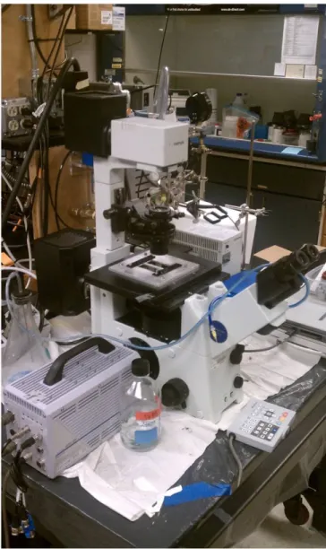
Figure 4.3: Microfluidic Device Testing Setup
4.6
Sample Collection
Droplets emerged from the output triangle along with excess lipid. A 1 mL pipetter set at 250 µm was placed at the edge of the PDMS and glass. The droplets and excess lipid were then captured and pipetted into a 3 mL serum vial. On completion of the sample collection, the vial was capped and placed in a refrigerator at 4°C.
Figure 4.4: Microfluidic Droplet Collection Methods
4.7
Acoustic Droplet Vaporization
A heated water bath was placed on an inverted microscope with a 100x water immersion objective. A hydrophone was placed in the focused region of the microscope until the tip was visible. A transducer was submerged in the water bath and focused to the hydrophone which was also in the focus of the microscope. Then, the hydrophone was removed and a cellulose testing tube was placed in the optical focus. A cellulose testing tube was made with a brass “U” shaped rod, Tygon tubing, and a small amount of cellulose tubing. Tygon tubing was hot glued to one side of the brass rod. A piece of cellulose tubing was then glued into the Tygon tubing. The cellulose tube was then hydrated and another piece of Tygon tubing was glued to the cellulose tubing. The piece of Tygon tubing was then glued to the other side of the brass rod creating a tight area of cellulose tubing in the “U” of the brass rod.
the droplet was activated to a gas bubble. Video was taken before and after activation with the use of a high-speed camera.
Figure 4.5: Acoustic Droplet Vaporization Testing Setup
4.8
Sample Processing
Image J was used to analyze the diameter of the droplets produced in the mi-crofluidic device and the droplets before activation. A microscope reticle was used for
distance calibration of the video images. Production rates were determined by count-ing the amount of droplets that passed a given distance on the video in a set time provided by the high-speed camera. Populations of data were imported into Excel for data processing.
Chapter 5
Results
5.1
Aim 1: Design a versatile microfluidic device to
create a spectrum of droplet sizes with different
materials.
“This research was a collaboration between UNC and UCI. Roger Shih and David Bardin were the main contributors in updating device designs and microfluidic wafer fabrication methods.”
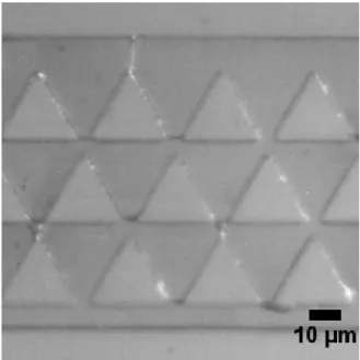
Figure 5.1: Microfluidic Device Filter System
Figure 5.2: “V” Shape Collection System
5.2
Aim 2: Precisely control the input of the target
reagents into the microfluidic device.
Initially, two syringe pumps were used. Unfortunately, this particular setup made it difficult to simultaneously control two syringe pumps, especially with the low viscosity PFP in a horizontal syringe. Initial thoughts by the author were that the syringe pumps maintained a lot of give in relation to the plastic syringe holding the reagent and that the system would not stay stable even after an adequate soak time. This created samples with a lot of size variation. Korczyk et al.(Korczyk et al., 2010) showed that
there was a large amount of variation with syringe pumps and offered a simple low cost alternative. The basic design used a pressure vessel with an input and output. This design was used as the basis for the pressure control flow system shown here. The pressure control flow system ensured that only small amounts of material needed to be used, allowed for effortless control of reagent flow, and the eventual creation of sub-micron droplets.
Figure 5.3: Consistent Monodispersed Droplet Production
5.3
Aim 3: Create uniform/monodisperse micron and
sub-micron samples.
Figure 5.4: Initial Coalescence
Figure 5.5: Initial Population Distributions
Figure 5.6: Uniform Sub-micron Droplet Production
5.4
Aim 4: Initiate acoustic droplet vaporization to
demonstrate controlled activation and overall
ex-pansion.
Figure 5.7: Acoustic Droplet Vaporization
5.5
Aim 5: Show that the vehicles will maintain
sta-bility over time.
To reiterate, the initial droplets created during this study were unable to be removed from the microfluidic device, which meant that they were not stable enough to last for an applicable time frame. This caused two iterations of lipid compositions to be created and a wedge collection style to be implemented. This allowed samples to be tested at incremental times through the span of two weeks. The results showed that the droplet diameters maintained a similar size and distribution compared to the day they were created. This then correlated to the droplets lasting an industrially applicable time frame similar to creation, shipping, storage, and medical use.
Figure 5.8: Stability of Droplets over 2 Weeks
Chapter 6
Results
The work presented here shows how improvement in different areas of the project culminated in the advancement of the ADV agent field. Microfluidic changes, reagent optimization, flow delivery mechanism and collection protocol all played a major role in the overall success of the project.
Microfluidics have allowed for the creation of monodispersed ADV agents. The initial microfluidic device was overhauled to allow for a smaller orifice and superior debris filters. The advancement in the microfluidic design allowed for progressively smaller droplets. Initial droplets were created with a diameter that was approximately 20 µm. The finalized design, on the other hand, produced droplet diameters that were
∼7 µm.
a necessary amount of time for sample collection. The pressure control flow system also allowed for the introduction of the term “nano tip-streaming”. This type of microfluidic droplet production enabled sub-micron droplets to be created.
Finally, the sample had to be collected and transported to be viable for any ap-plication. The initial collection mechanism caused a pressure gradient at the output and depending upon the amount of material in the output orifice, the diameter would vary. This variation in the sample would cause the standard deviation to be too high rendering the sample unusable. The need for an output with a minimized pressure gradient was sought after and it was found that a wedge cut at the orifice of the device allowed for easier collection and did not alter the production of the sample based on the amount of material at the output.
Chapter 7
Conclusion
Chapter 8
Publications
• Precision Manufacture of Phase-Change Perfluorocarbon Droplets using Microflu-idics (9.1)
• Published in Ultrasound in Medicine & Biology
– Reproduced with permission from Elsevier. – Vol. 37, No. 11, pp. 1952-1957, 2011 – Final form August 17th
• High-speed, clinical-scale microfluidic generation of stable phase-change droplets for gas embolotherapy (9.2)
– Published in Lab on a Chip
∗ Reproduced by permission of The Royal Society of Chemistry.
– DOI: 10.1039/C1LC20615J – Accepted September 5th
• Microfluidic generation of acoustically active nanodroplets (9.3)
8.1
Precision Manufacture of Phase-Change
Perfluo-rocarbon Droplets using Microfluidics
1Thomas D. Martz1, Paul S. Sheeran2, David Bardin3, Abraham P. Lee3, and Paul A.
Dayton2,∗
1Curriculum of Applied Sciences and Engineering - Materials Science, The
Univer-sity of North Carolina, Chapel Hill, NC, 27599
2Joint Department of Biomedical Engineering, The University of North Carolina
and North Carolina State University, Chapel Hill, NC, 27599
3Department of Biomedical Engineering, The University of California at Irvine,
Irvine, CA, 92697
8.1.1
Abstract
Liquid perfluorocarbon droplets have been of interest in the medical acoustics com-munity for use as acoustically activated particles for tissue occlusion, imaging, and therapeutics. To date, methods to produce liquid perfluorocarbon droplets typically result in a polydisperse size distribution. Because the threshold of acoustic activation is a function of diameter, there would be benefit from a monodisperse population to pre-serve uniformity in acoustic activation parameters. Through the use of a microfluidic device with flow-focusing technology, the production of droplets of perfluoropentane with a uniform size distribution is demonstrated. Stability studies indicate that these droplets are stable in storage for at least two weeks. Acoustic studies illustrate the thresholds of vaporization as a function of droplet diameter, and a logarithmic rela-tionship is observed between acoustic pressure and vaporization threshold within the size ranges studied. Droplets of uniform size have very little variability in acoustic va-porization threshold. Results indicate that microfluidic technology can enable greater manufacturing control of phase-change perfluorocarbons for acoustic droplet vaporiza-tion applicavaporiza-tions.
Keywords: Acoustic droplet vaporization, Ultrasound, Monodisperse, Perfluoropen-tane, Microfluidic
8.1.2
Introduction
Acoustic Droplet Vaporization Agents
In acoustic droplet vaporization (ADV), acoustic pressure delivered to a liquid droplet by an ultrasound (US) transducer provides the additional energy necessary to induce a liquid-to-gas phase transition. This phase transition allows for unique ap-plications that are not possible with standard microbubble contrast agents, because ADV agents exhibit a very large volume change after activation. In addition, ADV agents are typically poorly echogenic in their liquid form, but highly echogenic as gas bubbles.
The basic construction of an ADV agent consists of a volatile liquid core that can be converted to a gas with additional energy. Typically, ADV droplets consist of perfluo-rocarbons (PFC) such as perfluoropentane (PFP) (Zhang et al., 2010), perfluorohexane (PFH) (Giesecke and Hynynen, 2003; Fabiilli et al., 2010b), or perfluorooctane (Fabiilli et al., 2009). The most commonly used PFCs, PFP and PFH, have boiling points near physiological temperatures (29°C and 56°C, respectively). Recently, stabilization and ADV capability of droplets of liquid perfluorobutane (boiling point of -1.7°C) has been demonstrated (Sheeran et al., 2011a).
Producing (PFC) droplets in the micron and sub-micron range increases the Laplace pressure exerted on the liquid core, enabling small droplets to be maintained in liquid form even above their vaporization temperature. The addition of a stabilizing shell reduces droplet coalescence and increases stability of the emulsions (Kripfgans et al., 2005; Rapoport et al., 2009b; Sheeran et al., 2011a). Commonly utilized methods of producing PFC droplets include sonication or high-speed mechanical agitation of the host solution, which typically results in a polydisperse population (Fabiilli et al., 2010b; Rapoport et al., 2010).
Acoustic Droplet Vaporization Applications
Liquid perfluorocarbon droplets have been shown to provide ultrasound image con-trast (Kripfgans et al., 2002; Marsh et al., 2007), although the backscatter is notably less than similarly sized microbubble agents. One of the first commercial applications of perfluorocarbon droplets for US contrast enhancement was Echogen (Sonus Phar-maceuticals, Bothell, WA, USA), a perfluoropentane emulsion (Quay, 1998). Clinical trials for Echogen were abandoned in 2000 before FDA approval could be obtained.
Once vaporized, ADV agents are readily detectable by an imaging system even at low concentrations. In very small amounts, droplets when converted to bubbles through
ADV could act as point beacons for phase aberration corrections (Apfel, 1998; Haworth et al., 2008). The unique advantages of ADV droplets in the 100-nm size range is that they have the potential to extravasate from the vasculature and into the tissue, enabling ADV-based contrast imaging or therapy to extend beyond the vascular space, where traditional microbubbles cannot access (Rapoport et al., 2007; Rapoport et al., 2009a; Sheeran et al., 2011a).
One of the most well studied applications of ADV is embolotherapy. This tech-nique enables the intentional creation of an occlusion in a specific tissue to limit blood flow. This has been proposed to treat renal cell carcinoma, to reduce blood loss for hypervascular tumors, and to treat hemorrhaging (Kripfgans et al., 2002; Zhang et al., 2010). Kripfgans et al. (2005) (Kripfgans et al., 2005) demonstrated that a filtered emulsion of droplets, which is intra-arterially injected, can reduce kidney perfusion by 70 %. This level of organ perfusion reduction has the ability to cause ischemic necro-sis for therapeutic applications, or it can enhance the utility of radiofrequency tissue ablation by minimizing thermally dissipative effects due to reduced flow (Kripfgans et al., 2005). A second application of ADV agents is site-specific therapeutics, where the goal is to deliver a potent agent only to the disease site while minimizing systemic effects. The ADV-mediated delivery of a chemotherapeutic drug directly to the tumor has been shown to mediate regression of ovarian and breast cancer (Rapoport et al., 2009b). ADV agents that have the ability to carry a therapeutic payload to a desired vessel could be combined with vessel occlusion upon activation to allow for an increase in residence time of the therapeutic agent (Fabiilli et al., 2010b).
With spatial and temporal control over ADV agent activation, ADV agents can be used as a nucleation site for high-intensity focused ultrasound (HIFU) tumor ablation. During HIFU, the microdroplets can be activated to increase the therapeutic effect or decrease the treatment time (Zhang and Porter, 2010; Zhang et al., 2011).
Considerations of ADV agent size distribution
at lower energies and the resulting bubbles can influence the threshold energy for the smaller droplets (Lo et al., 2007), confoundingin-vitro characterization of vaporization
thresholds. Because microbubbles combined with high acoustic pressures can lead to unwanted bioeffects (Miller et al., 2008), it may be desirable to perform ADV at the minimum acoustic pressure required. A polydisperse sample may require a higher pres-sure to efficiently vaporize the entire population due to smaller droplets requiring more energy.
For micron-sized ADV agents, one of the primary applications is vessel occlusion, where it may be important to have a well-characterized distribution of droplet sizes to target a specific vascular diameter while not affecting other vessels (Kripfgans et al., 2005). For the same reasons, a droplet designed for imaging applications that is too large could lodge in the lungs or other organs after IV injection, leading to undesired vessel occlusion. All of these limitations are motivating reasons for precise size control of ADV agents.
Previous studies to improve the size distribution characteristics of perfluorocarbon droplets have involved microfluidic sorting (Huh et al., 2007) and filtering (Kripfgans et al., 2005). The microfluidics platform is well known for the ability to create particles, droplets (Tan et al., 2004; Xu et al., 2006; Teh et al., 2008), microbubbles (Hettiarachchi et al., 2007a), and multi-layer particles (Hettiarachchi et al., 2009) of uniform size. In this manuscript, we assess the feasibility for producing a monodispersed ADV agent through a microfluidic technique to achieve uniform activation thresholds.
8.1.3
Materials and Methods
Reagent Preparation
Lipid PFP was purchased from FluoroMed, L.P. (Round Rock, Texas, USA). Lipid solutions were created using a 9:1 molar ratio of 1,2-distearoyl-sn-glycero-3-phosphocholine (DSPC) (Avanti Polar Lipids, Alabaster, AL, USA) and 1,2-distearoyl-sn-glycero-3-phosphoethanolamine-N[methoxy-(polyethylene glycol)-2000] (DSPE-PEG2000) (Avanti Polar Lipids) in a 110-mL solution of deionized (DI) water, glycerol (Fisher Scientific, Pittsburgh, PA, USA), propylene glycol (Fisher Scientific, Pittsburgh, PA, USA), and pluronic F-68 (Sigma-Aldrich Corporation , St. Louis, MO, USA).
Fifty mg of DPSC and 19.6 mg DSPE-PEG2000 were dissolved in chloroform. The chloroform was then evaporated with N2, after which 50 mL of DI water was added and the resulting solution was sonicated for 20 minutes. After sonication, 47 mL DI
water, 2 mL glycerol, 1 mL propylene glycol, and 10 mL pluronic F-68 were added. The solution was vortex mixed for 1 minute and then sonicated for 10 minutes.
Microfluidic Device Fabrication
The process for developing the microfluidic wafer has been previously described by Hettiarachchi el al. (2009) (Hettiarachchi et al., 2009). Briefly, the channels were created using Illustrator (Adobe, San Jose, CA, USA) and printed (20,000 dpi) by CAD/Art Services (Brandon, OR, USA). In a clean room, the wafer was first oxidized in oxygen plasma and then spin-coated with a UV curable epoxy (SU-8-25, MicroChem, Newton, MA, USA). On exposing the wafer to UV light, the channel patterns develop to use as a negative for device production.
With the wafer in a petri dish, Polydimethylsiloxane (PDMS) (Dow Corning, Mid-land, MI, USA) and a curing agent were poured over the wafer at a 10:1 ratio, respec-tively. This was then placed under vacuum for 24 h and then cured at 60°C overnight. After the PDMS was cured, the individual microfluidic devices were removed from the wafer. The individual microfluidic device and a clean microscope slide (2947-75X25, Corning, Corning, NY, USA) were placed in a plasma cleaner (Harrick Plasma, Ithaca, NY, USA) and exposed to a plasma field under a controlled pressure of 500 mTorr for 3 minutes. Upon completion of the plasma cleaning process, the PDMS and glass slide were immediately joined, forming complete microchannels. One minute after the bond was established, DI water was injected into the channels to create a hydrophilic environment.
Microfluidic Experimental Apparatus
The microfluidic experimental apparatus was set up similar to that as described previously by Kaya et al. (2010)(Kaya et al., 2010). Briefly, the microfluidic device was secured to a moving stand on an inverted microscope (Olympus 1X71 microscope, Center Valley, PA, USA), and viewed with a 50X NA = 0.5 objective. A high speed camera (Fastcam APX-RS, Photron, Inc., San Diego, CA, USA) was used to capture images and videos of the device output. Reagents were injected from syringes into device channels through Tygon S-54-HL tubing (Saint-Gobain Performance Plastics, Akron, OH, USA). Calibrated syringe pumps (Harvard Apparatus, Holliston, MA, USA) were used to control rate of material flow in individual microchannels.
Sample Production
in the system required a few minutes to equalize. This process was repeated across a range of different flow rates, as described in Table 8.1. To determine the production rate for the microfluidic device, high-speed video analysis of the droplet production was performed. Time stamps enabled the determination of droplet production rate.
Acoustic Experimental Apparatus
The experimental setup to determine droplet vaporization thresholds was similar to that previously described by Sheeran et al. (2011)(Sheeran et al., 2011a). Briefly, a heated water bath maintained at 37°C was connected to an inverted microscope. Droplets were injected through a nearly acoustically and optically transparent mi-crocellulose capillary tube with an inner diameter of 200 µm (Spectrum Labs, Inc., Greensboro, NC, UNC). A 5-MHz piston transducer (IL0506HP, Valpey Fisher Corp., Hopkinton, MA, USA) was positioned in the water bath confocally with a water immer-sion microscope objective (100x, NA=1.0). The output of the ultrasound transducer was calibrated by inserting a needle-hydrophone (HNA-0400, Onda Corp., Sunnyvale, CA, USA) into the experimental system at the exact location where the samples are positioned during activation studies (the focus of the microscope objective). Droplets were exposed to single 10-cycle sinusoidal pulses while the ultrasound pressure was increased incrementally until droplet vaporization was observed. The procedure was repeated for at least 20 droplets from each size distribution to verify droplet size and threshold.
Stability Analysis
Droplets were stored at 4°C in 3-mL vials until sampling. For analysis, a 25-µliter aliquot of droplets was placed on a glass slide, and images were captured with the Photron Fastcam camera. Size measurements were performed in ImageJ (NIH, Bethesda, MD, USA) by comparison to a calibrated reticle (Edmund Industrial Optics, Barrington, NJ, USA). A minimum of 50 droplets was measured for each population.
8.1.4
Results
The dimensions of the microfluidic device, material composition, and flow rates all have the ability to alter the composition of the resulting droplet. Due to the micro-fabrication process, there are minute variations from device to device (we measured a 13% deviation in orifice widths across 10 devices). With this in mind, only one device was used for the duration of production to ensure that the dimensions of the device were unchanged. The material compositions also went unchanged to ensure that the
Figure 8.1: High-speed video frames of microfluidic droplet production at diameters of (a) 20.4±0.3 µm, (b) 16.2±0.5 µm, (c) 12.6±0.5 µm, (d) 10.3±0.4 µm and (e) 7.4±0.4 µm, corresponding to lipid and PFP flow rates of lipid 40 µL/min; PFP 12.5 µL/min, lipid 31 µL/min; PFP 15 µL/min, lipid 40 µL/min; PFP 15 µL/min, lipid 50 µL/min; PFP 15 µL/min, lipid 60 µL/min; and PFP 13.9 µL/min, respectively.
droplets would experience a standardized reaction to the US pressure.
Precision Size Control
The flow rates were varied over five sets of conditions for the duration of the ex-periment to alter the droplet diameter. Results illustrated that by varying flw rates, the PFP population diameters could be carefully selected. In general, as the lipid flow rate was increased, droplet size decreased (Figure 8.1). As the PFP flow rate was in-creased, droplet size increased. Table 2 lists the flow rates, mean droplet size, standard deviation, and polydispersity index (Xu et al., 2006).
For the populations studied, the standard deviation was largest for the smallest droplets (SD=0.4 for the 7.4 micron population) and smallest for the largest droplets (0.3 for the 20.4 micron population). All populations had a polydispersity index of 5.1 or less.
Production Rate
The 20-µL/min lipid and the 12.5-µL/min PFP flow rates, which resulted in 20.4 mi-cron droplets, had a production rate of 1.85x10⁴ droplets produced per second (slowest
production sample); whereas the 60-µL/min lipid and 13.9-µL/min PFP flows, which produced 7.4 micron droplets, had a production rate of 1.65x10⁵ droplets per second
(fastest production sample). Table 3 lists the production rates for the 5 samples.
Acoustic Responses
Table 8.1: Polydispersity data for the five studied droplet populations from the day the droplets were created and at three days, one week and two weeks.
Figure 8.2: Average pressure of vaporization vs. average droplet diameter. Error bars
indicate standard deviations in pressure and diameter. The trendline is logarithmic.
The data trend suggests a logarithmic relationship (P = -1.80ln(D) + 7.72, R² = 0.97), as predicted by the Antoine equation.
Long-tem stability
Figure 8.3: Microscopy images of droplets one week apart illustrating size stability. (a–e) One week after production— populations of mean diameter of (a) 20.4±0.3 µm, (b) 16.2±0.5 µm, (c) 12.6±0.5 µm, (d) 10.3±0.4 µm and (e) 7.4±0.4 µm. (f–j) Two weeks after production—populations corresponding to (a–e), respectively, with mean diameters of (f) 20.4±0.5 µm, (g) 15.5±0.5 µm, (h) 12.2±0.4 µm, (i) 10.8±0.4 µm and (j) 7.5±0.7 µm.
Table 8.2: Production rates for droplets produced with microfluidics under varying input flow conditions.
8.1.5
Discussion
The method described here demonstrates the potential of production of uniform-sized droplets for acoustic droplet vaporization using microfluidics. Data illustrate that this technique enabled production of a population of droplets where each droplet responded similarly to the same acoustic parameters because of uniform size. One ad-vantage of utilizing such uniform droplets would include the ability to use the lowest acoustic pressure possible for vaporization (because all droplets would respond sim-ilarly), thereby achieving the highest vaporization efficiency for the lowest acoustic pressure. Keeping the acoustic pressure as low as required would conform to the “As Low As Reasonably Achievable (ALARA) Principle” for clinical ultrasonics. Other po-tential advantages of uniform sized ADV agent production, although not demonstrated here, would be the ability to tailor droplet sizes for specific vessel occlusion, or to enable precision drug-loading for therapeutic-carrying ADV agents.
Microfluidic techniques have previously demonstrated unique utility in the con-trolled fabrication of droplets and microbubbles. The biggest limitation to this method to date is that the production rate is substantially slower than other droplet and mi-crobubble production methods. Even for the fastest production method here, it would require nearly 3 h to achieve 1x10⁹ droplets (a similar order of magnitude to the
concen-tration of microbubble contrast agents prepared by a mechanical agitation method). However, in the future microfluidic techniques may be scaled up to achieve higher throughput, although the need to maintain identical dimensions and flow rates to each orifice in order to preserve size uniformity presents a challenge. It should also be noted that although the smallest droplets described here were approximately 7 microns, which is likely too large for in vivo application, this size was limited only by our particular
system, and is not a fundamental limit of microfluidic droplet production. It is very rea-sonable to anticipate that by optimizing the channel dimensions, component flow rates, and the lipid/perfluorocarbon ratios, that droplets much smaller than 7 microns can be prepared. Prior studies have illustrated microfluidic production of liquid droplets as small as 100 nanometers (Tan and Lee, 2005).
8.1.6
Conclusion
diam-eter and ADV threshold agreed with the expected negative logarithmic response based on the size of the droplets. Droplet populations produced with microfluidics were stable within the two-week time period studied.
8.1.7
Acknowledgements
The authors would like to thank Jason Streeter for the preparation of the lipid solu-tion and Roger Shih for the microfluidic wafer fabricasolu-tion. Also, the authors appreciate the assistance from Dennis Given and Roshni Kothadia for their work in droplet char-acterization and data organization. This project was supported by R01EB008733 and R21EB011704.
8.2
High-speed, clinical-scale microfluidic generation
of stable phase-change droplets for gas
embolother-apy
2David Bardin,a Thomas D. Martz,b Paul S. Sheeran,c Roger Shih,a Paul A. Daytonc
and Abraham P. Lee∗a
aDepartment of Biomedical Engineering, University of California, 3406 Engineering
Hall, Irvine, CA, 92697, USA
bCurriculum of Applied Sciences and Engineering—Materials Science, The
Univer-sity of North Carolina, Chapel Hill, NC, 27599, USA
cJoint Department of Biomedical Engineering, The University of North Carolina
and North Carolina State University, Chapel Hill, NC, 27599, USA
8.2.1
Abstract
In this study we report on a microfluidic device and droplet formation regime ca-pable of generating clinical-scale quantities of droplet emulsions suitable in size and functionality for in vivo therapeutics. By increasing the capillary number—based on
the flow rate of the continuous outer phase—in our flow-focusing device, we examine three modes of droplet breakup: geometry-controlled, dripping, and jetting. Operation of our device in the dripping regime results in the generation of highly monodisperse liquid perfluoropentane droplets in the appropriate 3–6 µm range at rates exceeding 105
droplets per second. Based on experimental results relating droplet diameter and the ratio of the continuous and dispersed phase flow rates, we derive a power series equa-tion, valid in the dripping regime, to predict droplet size, Dd ∼=27(QC/QD)−5/12. The
volatile droplets in this study are stable for weeks at room temperature yet undergo rapid liquid-to-gas phase transition, and volume expansion, above a uniform thermal activation threshold. The opportunity exists to potentiate locoregional cancer therapies such as thermal ablation and percutaneous ethanol injection using thermal or acoustic vaporization of these monodisperse phase-change droplets to intentionally occlude the vessels of a cancer.
8.2.2
Introduction
Embolization has emerged as an accepted modality for the treatment of various cancers, including hepatocellular carcinomas, hepatic metastases, and renal cell carci-nomas.(Goode and Matson, 2004) The intentional occlusion of a vessel, embolization enables the reduction of blood flow into or out of that vessel, and has typically been used in cancer therapies to produce local ischemia resulting in tumor necrosis. Estab-lished methods of embolization include the placement of a metal coil or soluble gelatin sponge within the target blood vessel, or the injection of chemical or particulate agents such as ethanol or polyvinyl alcohol particles to reduce blood flow at the site of injec-tion or immediately downstream.(Goode and Matson, 2004; Kalman and Varenhorst, 1999)
Recently the field of medical ultrasound has shown much interest in gas embolother-apy, in which acoustic or thermal energy induces a droplet emulsion with a volatile liquid core to undergo a liquid-to-gas phase transition, and volume expansion, to strategi-cally form gas emboli in vivo, as shown in Fig. 8.4. Acoustic droplet vaporization
(ADV) specifically refers to the use of focused ultrasound to induce such a transition, in which the applied acoustic pressure supplies the necessary energy to induce super-heated droplet emulsions to vaporize into microbubbles. The phase-change typically results in microbubbles five to six times larger in diameter than the original droplets, enabling these gas bubbles to occlude vessels of sufficiently small diameters, such as capillaries and some arterioles.(Apfel, 1998; Kripfgans et al., 2000)
Studies thus far have investigated the usefulness of ADV agents to enhance con-trast in ultrasound imaging,(Kripfgans et al., 2002) to deliver therapeutics,(Rapoport et al., 2010; Fabiilli et al., 2010a; Fabiilli et al., 2010b) for enhanced thermal delivery alongside highintensity focused ultrasound (HIFU),(Zhang and Porter, 2010) and for occlusion in animal models.(Zhang et al., 2010) The choice of liquid core consists of a number of perfluorocarbons, including perfluoropentane,(Kripfgans et al., 2000; Fabi-illi et al., 2010b; FabiFabi-illi et al., 2010a; Zhang et al., 2010; Kripfgans et al., 2004; Lo et al., 2007; Rapoport et al., 2009b; Giesecke and Hynynen, 2003; Schad and Hynynen, 2010) perfluorohexane, (Fabiilli et al., 2010b; Giesecke and Hynynen, 2003) perfluorooc-tane,(Fabiilli et al., 2009) and perfluorobutane.(Sheeran et al., 2011a) Encapsulation of the liquid core inside a lipid, albumin or polymer shell reduces coalescence among
Figure 8.4: Schematic of the liquid-to-gas phase transition of a phase-change droplet. When presented with acoustic or thermal stimuli of a threshold amount, the volatile liquid core of the droplet rapidly vaporizes within the lipid shell. Expansion to a gas bubble enables the intentional occlusion of a target vesselin vivo. Other possible stimuli
include light and mechanical pressure.
the droplet population and increases the Laplace pressure sufficiently to enable these volatile emulsions to remain as superheated droplets at body temperature.(Kripfgans et al., 2000; Giesecke and Hynynen, 2003)
Current methods to generate these phase-change droplets— which include soni-cation and high-speed mechanical agitation— typically result in a polydisperse size distribution(Rapoport et al., 2010; Fabiilli et al., 2010a) and a nonuniform acoustic activation threshold, as well as droplets either too large for passage through the lung capillaries (>6 µm) or too small to occlude the desired vessel (<1 µm).(Kripfgans et al., 2000; Zhang et al., 2010) Thus required are secondary methods of size selection such as filtering(Kripfgans et al., 2002; Lo et al., 2006) or microfluidic sorting(Huh et al., 2007) to control the sizes of these distributions. The Antoine equation predicts a negative logarithmic relationship between vaporization energy and droplet diameter,(Rapoport et al., 2009b) meaning that small droplets require more energy to vaporize than larger droplets due to increased Laplace pressure. Hence, narrowing the droplet size distribu-tion such that it is highly monodisperse should result in a uniform response to focused acoustic pressure. As well, a monodisperse population of ADV agents may better target a specific vessel diameter to improve occlusion efficiency and efficacy, and would signif-icantly reduce unwanted bioeffects seen in vivo, including delayed febrile-like reactions
and respiratory distress.(Zhang et al., 2010; Kripfgans et al., 2000)
et al., 2007b; Talu et al., 2007; Talu et al., 2008) in the micrometre diameter range with high uniformity. Yet despite the attractiveness of precision control over size, shape, and composition, these systems have traditionally been viewed as unviable as bulk manufacturing processes owing to relatively low generation rates. At present, report-ing of clinical-scale generation of droplet or microbubble emulsions has been limited, and virtually absent for emulsions truly useful for in vivo intravenous or intra-arterial
therapeutics. Most recently Castro-Hernandez et al.(Castro-Hernandez et al., 2011) de-scribed a new regime for microbubble generation dependent on the formation of a strong pressure gradient at the bubbleproducing region. Approximately 5 µm in diameter gas-in-water bubbles were successfully generated at the tip of a long gas ligament with rates exceeding 105 Hz from a single channel, though bubbles were unstable due to the lack
of significant surfactant or lipid shells. Far less impressive per-channel frequencies have been observed in liquid–liquid droplet generation systems. Nisisako and Torii(Nisisako and Torii, 2008) achieved a throughput of 320 mL h−1 in generating approximately 100
µm droplets using a multilayer device with 256 droplet formation units and a breakup rate of 1.4x10³ droplets per second per cross-junction. Kobayashi et al.(Kobayashi
et al., 2007) reported the formulation of oil-in-water emulsions at cumulative rates up to 2.2x10⁴ Hz using a total of 1500 submicron-channels on single-crystal silicon plates,
although the emulsions were only moderately monodisperse with a minimum coeffi-cient of variation (CV) of 9%. In fact, frequency distributions for various liquid–liquid droplet generation systems, whether water in oil or oil in water, rarely exceed several thousand droplets per second from a single channel in forming droplets seldom smaller than 10 µm in diameter.(Teh et al., 2008) From a healthcare perspective, one could comment that there is no practical use for these aforementioned emulsions due to ei-ther insufficient quantity or inappropriate characteristics of the emulsion. Thus, a need in microfluidics still exists for systems capable of generating clinical-scale amounts of droplet or microbubble emulsions with suitable size and functionality for therapeutics. To overcome the limitations of past droplet generation systems, we considered the basic mechanisms of droplet generation with the intent to find a possible route to pro-duce, in mass, micrometre-scale droplets with engineered biology. Recent publications on the physics of fluids have reported the observation of a number of distinct droplet formation modes in flowfocusing microfluidic devices.(Anna and Mayer, 2006; Cubaud and Mason, 2008) Under controlled experimental conditions, such a device transitions from geometry-controlled mode to dripping to jetting, affecting the size and genera-tion frequency by up to an order of magnitude. In particular, Anna and Mayer(Anna
Figure 8.5: Geometry of the device for the generation of liquid perfluoropentane phase-change droplets. (a) Schematic view of the microfluidic flow-focusing device. All chan-nels are rectangular with a height of 25 µm. (b) Image of the flow-focusing region. Lipid solution and liquid perfluoropentane distribution channels measure 38 µm in width and direct flows to a 7 µm orifice. Expanding nozzle geometry precedes a postorifice channel 30 µm in width. (c) Overhead view of the assembled PDMS device relative to a dime.
and Mayer, 2006) allude to the dripping mode of droplet breakup as a method to yield droplets smaller than the minimum device feature size with a shorter primary breakup period than other modes, as yet demonstrated in the literature with a health-care intent. We thus set out to use the dripping regime to meet our objective of the clinic-ready manufacture of liquid perfluoropentane droplets as phase-change agents for cancer treatment.
In this work we present a microfluidic device, operated in the dripping regime, for the super high-speed generation (>105 Hz) of monodisperse liquid perfluoropentane
droplets in the desired size range for gas embolotherapy. Resulting droplet popula-tions exhibit polydispersity index values of <5%, are stable at room temperature for several weeks, and are thermally vaporized at 88°C in a water bath. These liquid perfluoropentane droplets thus exhibit phase-change and are ideal for targeted vessel occlusion alongside such cancer therapies as HIFU, radiofrequency ablation (RFA), laser ablation (LA), laser-induced thermotherapy (LITT), and chemotherapy. Our mi-crofluidic device, shown in Fig. 8.5, features a hydrodynamic flow-focusing region and expanding nozzle geometry to generate monodisperse liquid perfluoropentane droplets encapsulated in a lipid shell.
8.2.3
Materials and methods
The microfluidic device, made of polydimethylsiloxane (PDMS) on a glass substrate, consists of fixed geometric channels designed to direct liquid perfluoropentane and a lipid solution to an orifice 7 µm in width. Filter channels of the same dimension immediately follow both inlets to prevent clogging at the orifice. Serpentine distribution channels increase the resistance between inlets and the orifice chamber, minimizing the susceptibility of droplet generation to disruptions in the fluid flows and increasing the pressure drop along the longitudinal axis of the device. Liquid perfluoropentane and lipid distribution channels each measure 38 µm in width. The post-orifice channel measures 30 µm in width.
Device operation: droplet formation regimes
The principle behind a microfluidic flow-focusing system is to force a central stream of a dispersed phase and two side sheath flows of a continuous phase through a small orifice, causing a focusing effect and a breaking of the thread at the orifice into uniform emulsions.(Tan et al., 2006)
Most traditional flow-focusing devices have been operated in the geometry-controlled mode, termed for the large dependence of droplet size on the smallest feature size in the device—the orifice. In this mode droplets break off from the dispersed phase fin-ger following a protrude-and-retract mechanism.(Garstecki et al., 2005) Droplets in the geometry-controlled mode are highly monodisperse but limited in minimum size by the width of the orifice.
An increase in the capillary number Ca = ηV/γEQ, where η is the viscosity, V
is the superficial velocity of the continuous outer phase, and γEQ is the equilibrium
surface tension between the two fluid phases, leads to droplet generation in the dripping regime.(Anna and Mayer, 2006) This regime produces monodisperse droplets smaller than the size of the orifice due to narrowing of the dispersed phase finger. The dripping mode is characterized by a dispersed phase tip that does not retract but rather remains at a fixed location in the orifice, generating a stream of droplets off the tip due to Rayleigh capillary instability.
A further increase in the capillary number leads to droplet generation in the jetting mode, wherein the dispersed phase finger extends far into the post-orifice channel. Droplets, which break off the tip of the dispersed phase finger due again to Rayleigh capillary instability, tend to be as large as or larger than the orifice width in the jetting mode and may be polydisperse.(Anna and Mayer, 2006)
By adjusting the flow parameters and continuous phase viscosity, we thus aimed to operate our flow-focusing microfluidic device in the dripping regime to attain droplets
of the desired size for gas embolotherapy (1–6 µm in diameter).
Microfabrication and assembly
Standard soft lithography techniques(Xia and Whitesides, 1998) were used to fab-ricate the microfluidic devices. Devices were designed as vector-based fluidic channel geometries in Illustrator (Adobe) and printed at 20 000 DPI by CAD/Art Services. In a class 10,000 clean room, a 25 µm layer of a UV-curable epoxy (SU8-25, MicroChem) was spun onto a 3 inch silicon wafer and exposed to UV-light through the photomask and developed.
Next, PDMS (Sylgard 184, Dow Corning), consisting of 10 : 1 prepolymer to curing agent, was poured over the patterned silicon wafer in a Petri dish to mold a silicon elastomer replica. The Petri dish was then vacuumed for at least half an hour to degas the PDMS and left overnight in a 70°C temperaturecontrolled dry oven to cure fully. The device was peeled from the hard master in a laminar flow chamber and inlets and outlet were punched using a blunt 18G needle. A soda lime glass slide was cleaned with isopropyl alcohol prior to use as the substrate. The cured PDMS device and clean glass slide were bonded after 150 seconds in air plasma at 250 milliTorr. DI water was added to the outlet after plasma preparation and allowed to wick in order to maintain the hydrophilicity of the channels.
Chemicals
A lipid shell was chosen over an albumin shell, as albumin shells have shown an increased tendency to become lodged in the pulmonary capillaries.(Zhang et al., 2010) Adapted from Hettiarachchi et al.,(Hettiarachchi et al., 2009) the lipid flow stream con-sists of an aqueous glycerol mixture with the stabilizing lipids DSPC sn-glycero-2-phosphocholine, Avanti Polar Lipids) and DSPE-PEG2000 (1,2-distearoyl-sn-glycero-3-phosphoethanolamine-N-[methoxy(polyethylene glycol)-2000], Avanti Po-lar Lipids). Briefly, 5 mg DSPC and 1.96 mg DSPE-PEG2000 were combined in a glass vial and dissolved in chloroform (CHCl3, Sigma) to form a homogeneous mixture. The