Research Article
a
April
2018
Special Issue: National Conference on Emerging Trends in Engineering 2018
Conference Held at Sri Venkatesa Perumal College of Engineering & Technology, Puttur, A.P., India
Computer Science and Software Engineering
ISSN: 2277-128X (Volume-8, Issue-4)
A Distributed Canny Edge Detector and Its Implementation
on FPGA
1
K D Mohana Sundaram, 2M Thulairam, 3D S Vanaja
Department of Electronics and Communication Engineering, Sri Venkatesa Perumal College of Engineering and Technology, Puttur, Andhra Pradesh, India
Email- ID [email protected], [email protected], [email protected]
Abstract—Edge detection is one of the key stages in image processing and objects recognition. The Canny edge detector is one of the most widely-used edge detection algorithms due to its good performance. In this paper, we present a distributed canny edge detection algorithm that results in significantly reduced memory requirements, decreased latency and increased Throughput with no loss in edge detection performance as compared to the original canny algorithm. The new algorithm uses a low-complexity 8-bin non-uniform gradient magnitude histogram to compute block-based hysteresis thresholds that are used by the canny edge detector. Furthermore, an FPGA-based hardware architecture of our proposed algorithm is presented in this paper and the architecture is synthesized on the Xilinx Virtex-5 FPGA. Simulation results are presented to illustrate the performance of the proposed distributed canny edge detector. The FPGA simulation results show that we can process a 512×512 image in 0.287ms at a clock rate of 100 MHz.
Index Terms— Canny Edge detector, Distributed Processing, Non-uniform quantization, FPGA
I. INTRODUCTION
Edge detection serves as a preprocessing step for many image processing algorithms such as image enhancement, image segmentation, tracking and image/video coding. Typically, edge detection algorithms are implemented using software. With advances in Very Large Scale Integration (VLSI) technology, their hardware implementation has become an attractive alternative, especially for real-time applications.
The Canny edge detector is predominantly used in many real-world applications due to its ability to extract significant edges with good detection and good localization performance. Unfortunately, the Canny edge detection algorithm contains extensive pre-processing and post-processing steps and is more computationally complex than other edge detection algorithms, such as Roberts, Prewitt and Sobel algorithms. Furthermore, it performs hysteresis thresholding which requires computing high and low thresholds based on the entire image statistics. This places heavy requirements on memory and results in large latency hindering real-time implementation of the canny edge detection algorithm.
Some approaches have been proposed for real-time edge detection. Alzahrani and Chen present an absolute different mask (ADM) edge detection algorithm and its pipelined VLSI architecture for real-time application [1]. But the edge detector in [1] offers a trade-off between precision, cost and speed, and its capability to detect edges is not as good as the Canny algorithm. There is another set of work on Deriche filters that have been derived using Canny’s criteria. For instance, it was stated in [2] that a network with four transputers takes 6s to detect edges in a 256 × 256 image using the Canny- Deriche algorithm, far from the requirement for real-time applications. The approach of [3] operates on two rows of pixels at a time. This reduces the memory requirement at the expense of a decrease in the throughput. Furthermore, it is known that the original Canny edge detection algorithm needs two adaptive image-dependent high and low thresholds to remove false edges. However, the algorithm in [3] just fixes high and low thresholds in order to overcome the dependency between the blocks, which results in a decreased edge detection performance.
In order to reduce memory requirements, decrease latency and increase throughput, a distributed Canny edge detection algorithm is proposed in [4]. The hysteresis threshold calculation is a key element that greatly affects the edge detection results. However, the original Canny algorithm computes the high and low thresholds for edge detection based on the entire image statistics, which prevents the processing of individual blocks independently. In [4], we proposed a new threshold selection algorithm based on the distribution of pixel gradients in a block of pixels to overcome the dependency between the blocks. However, in [4], the hysteresis thresholds calculation is based on a very finely and uniformly quantized 64-bin gradient magnitude histogram, which is computationally expensive and, thereby, hinders the real-time implementation. In this paper, a method based on non-uniform and coarse quantization of the gradient magnitude histogram is proposed.
ISSN(E): 2277-128X, ISBN: 978-93-87396-07-4, pp. 137-144
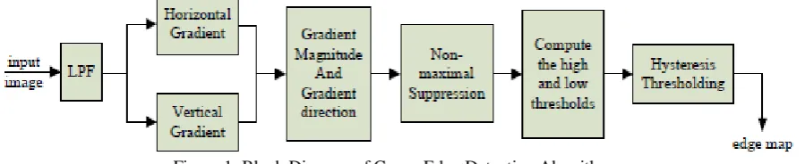
Figure 1. Block Diagram of Canny Edge Detection Algorithm.
This paper is organized as follows. Section 2 gives a brief overview of the original Canny algorithm. Section 3 presents the proposed distributed Canny edge detection algorithm which includes a novel method for the hysteresis thresholds computation based on a non-uniform quantized gradient magnitude histogram. The proposed hardware architecture and FPGA implementation of the proposed algorithm are described in Section 4. Simulation results are presented in Section 5. A conclusion is given in Section 6.
II. CANNY EDGE DETECTION ALGORITHM
Canny developed an approach to derive an optimal edge detector based on three criteria related to the detection performance. The model was based on a step edge corrupted by additive white Gaussian noise. A block diagram of the Canny edge detection algorithm is shown in Fig. 1. The original Canny algorithm [5] consists of the following steps:
1. Smoothing the input image by Gaussian mask. The output smoothed image is denoted as I(x, y).
2. Calculating the horizontal gradient Gx(x, y) and vertical gradient Gy(x, y) at each pixel location by convolving the image I(x, y) with partial derivatives of a 2D Gaussian functions.
3. Computing the gradient magnitude G(x, y) and direction θG(x, y) at each pixel location.
4. Applying non-maximum suppression (NMS) to thin edges.
5. Computing the hysteresis high and low thresholds based on the histogram of the magnitudes of the gradients of the entire image.
6. Performing hysteresis thresholding to determine the edge map.
III. PROPOSED DISTRIBUTED CANNY EDGE DETECTION ALGORITHM
The Canny edge detection algorithm operates on the whole image and has a latency that is proportional to the size of the image. While performing the original Canny algorithm at the block-level would speed up the operations, it would result in loss of significant edges in high-detailed regions and excessive edges in texture regions. Natural images consist of a mix of smooth regions, texture regions and high-detailed regions and such a mix of regions may not be available locally in every block of the entire image. In [4], we proposed a distributed Canny edge detection algorithm, which removes the inherent dependency between the various blocks so that the image can be divided into blocks and each block can be processed in parallel.
The input image is divided into m×m overlapping blocks. The adjacent blocks overlap by (L − 1)/2 pixels for a L × L gradient mask. However, for each block, only edges in the central n × n (where n = m + L − 1) non-overlapping region are included in the final edge map. Steps 1 to 4 and Step 6 of the distributed Canny algorithm are the same as in the original Canny algorithm except that these are now applied at the block level. Step 5, which is the hysteresis high and low thresholds calculation, is modified to enable parallel processing. In [4], a parallel hysteresis thresholding algorithm was proposed based on the observation that a pixel with a gradient magnitude of 2, 4 and 6 corresponds to blurred edges, psychovisually significant edges and very sharp edges, respectively. In order to compute the high and low hysteresis thresholds, very finely and uniformly quantized 64-bin gradient magnitude histograms are computed over overlapped blocks. If the 64-bin uniform discrete histogram is used for the high threshold calculation, this entails performing 64 multiplications and 64*Np comparisons, where Np is the total number of pixels in an image. Therefore, it is necessary to find a good way to reduce the complexity of the histogram computation.
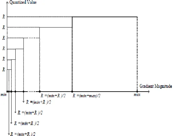
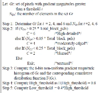
As in [6], it was observed that the largest peak in the gradient magnitude histograms after NMS of the Gaussian smoothed natural images occurs near the origin and corresponds to low-frequency content, while edge pixels form a series of smaller peaks where each peak corresponds to a class of edges having similar gradient magnitudes. Consequently, the high threshold should be selected between the largest peak and the second largest edge peak. A sample gradient magnitude histogram is shown in Fig. 2(b) for the 512×512 House image (Fig. 2(a)). Based on the above observation, we propose a non-uniform quantizer to discretize the gradient magnitude histogram. Specifically, the quantizer needs to have more quantization levels in the region between the largest peak A and the second largest peak B and few quantization levels in other parts. Fig. 3 shows the schematic diagram of the designed quantizer. Accordingly, n reconstruction levels can be computed as follows: R1 = (min + max)/2, (1) Ri+1 = (min + Ri)/2, i = 2, ..., n (2) where min and max represent, respectively, the minimum and maximum values of the gradient magnitude after NMS, and Ri is the reconstruction level. The proposed distributed thresholds selection algorithm is shown in Fig. 4. Let Gt be the set of pixels with gradient
magnitudes greater than a threshold t, and let NGt for t = 2, 4, 6, be the number of corresponding gradient elements in the
high-ISSN(E): 2277-128X, ISBN: 978-93-87396-07-4, pp. 137-144
detailed, moderately edged, blurred or textured, as shown in Fig. 4. Consequently, the set Gt = Gt=c can be selected for computing the high and low thresholds. The high threshold is calculated based on the histogram of the set Gc such that 20% of the total pixels of the block would be identified as strong edges. The lower threshold is the 40% percentage of the higher threshold as in the original Canny algorithm.
(a)
(b)
Figure 2. (a) original 512 X 512 house image (b) Histogram of the gradient magnitude after non-maximal suppression of the housing image.
ISSN(E): 2277-128X, ISBN: 978-93-87396-07-4, pp. 137-144
We compared the high threshold value that is calculated using the proposed distributed algorithm based on an 8-bin non-uniform gradient magnitude histogram with the value obtained when using a 16-bin non-uniform gradient magnitude histogram. These two high thresholds have similar values. Therefore, we use the 8-bin non uniform gradient magnitude histogram in our implementation.
Figure 4. Pseudo-code of the proposed distributed threshold selection scheme.
4. FPGA IMPLEMENTATION OF THE PROPOSED DISTRIBUTED CANNY ALGORITHM
In this section, we describe the hardware implementation of our proposed distributed Canny edge detection algorithm on the Xilinx Virtex-5 FPGA (XC5VSX240T). We provide a high-level overview (Section 4.1) followed by details of each of the units (Sections 4.2 through 4.6).
4.1. Architecture Overview
Depending on the available FPGA resources, the image needs to be partitioned into q sub-images and each sub-image is further divided into p m×m blocks. The proposed architecture, shown in Fig. 5, consists of q processing units in the FPGA and some Static RAMs (SRAM) organized into q memory banks to store the image data, where q equals to the image size divided by the SRAM size. Each processing unit processes a sub image and reads/writes data from/to the SRAM through ping-pong buffers, which are implemented with dual port Block RAMs (BRAM) on the FPGA. As shown in Fig. 5, each processing unit (PU) consists of p computing engines (CE), where each CE detects the edge map of an m×m block image. Thus, p · q blocks can be processed at the same time and the processing time for an N × N image is reduced, in the best case, by a factor of p · q. The specific values of p and q depend on the processing time of each PE, the data loading time from the SRAM to the local memory and the interface between FPGA and SRAM, such as total pins on the FPGA, the data bus width, the address bus width and the maximum system clock of the SRAM. In our application, we choose p = 2 and q = 8. In the proposed architecture, each CE consists of the following 6 units, as shown in Fig. 6:
1. Smoothening unit using Gaussian filter.
2. Vertical and horizontal gradient calculation unit. 3. Magnitude calculation unit.
4. Directional non-maximum suppression unit. 5. High and low threshold Calculation unit. 6. Thresholding with hysteresis unit.
ISSN(E): 2277-128X, ISBN: 978-93-87396-07-4, pp. 137-144
Figure 6. Block diagram of the CE (compute engine) for the proposed distributed Canny edge detection.
4.2. Image Smoothening
The input image is smoothened using a 3×3 Gaussian mask, as shown in Fig. 7(a). The Gaussian filter (Fig. 7(a))is separable and, thus, the implementation of the 2-D convolution with the 3×3 Gaussian mask is achieved using row and column 1- D convolutions. The proposed architecture for the smoothening unit is shown in Fig. 7(b).
(a)(b)
Figure 7. (a) Mask for the lowpass Gaussian filter with p = 0.0437; q = 0.9947; (b) Pipelined Image Smoothening Unit.
The main components of the architecture consist of a 1-D finite impulse filter (FIR) to process the data and the on-chip Block RAM (BRAM) to store the data. In our design, we adopt the Xilinx’s pipelined FIR IP core, which provides a highly parameterizable, area-efficient, high-performance FIR filter utilizing the structure characteristics in the coefficient set, such as symmetry and conjugacy. By exploiting the symmetry of the Gaussian filter, the architecture uses two multipliers to perform the 1-D convolution using a 3-tap filter. The address controller fetches the input image data from the local memory into the FIR core and, after the computation, it stores the results back in the BRAM.
4.3. Gradients and Gradient Magnitude Calculation
This stage calculates the vertical and horizontal gradients using convolution kernels. The kernels vary in size from 3 × 3 to 9×9, depending on the sharpness of the image. The Xilinx FIR IP core, which can support up to 256 sets of coefficients with 2 to 1024 coefficients per set, is used to implement the kernels. The whole design is pipelined, and thus the output is generated every clock cycle. This is input to the magnitude calculation unit which computes, at each pixel location, the gradient magnitude from the pixel’s horizontal and vertical gradients. The architecture of this unit is shown in Fig. 8. The gradient calculation architecture consists of two 1-D FIR models and the corresponding local memory. The filters for computing the horizontal and vertical gradient elements can process data in parallel. The magnitude computation consists of two multipliers and one square-root computation module, which are implemented by the Xilinx Math Function IP cores.
4.4. Directional Non Maximum Suppression
ISSN(E): 2277-128X, ISBN: 978-93-87396-07-4, pp. 137-144
Figure 8. Gradient and Magnitude Calculation Unit.
Figure 9. Directional Non Maximum Suppression Unit.
Figure 10.The architecture of the Threshold Calculation Unit.
4.5. Calculation of the hysteresis thresholds
ISSN(E): 2277-128X, ISBN: 978-93-87396-07-4, pp. 137-144
Figure 11. Pipelined architecture of the Thresholding Unit.
4.6. Thresholding with hysteresis
Since the output of the non maximum suppression unit contains some spurious edges, the method of thresholding with hysteresis is used. Two thresholds, high threshold ThH and low threshold ThL, which are obtained from the threshold
calculation unit, are employed. Let f(x, y) be the image obtained from the non maximum suppression stage, f1(x, y) be the strong edge image and f2(x, y) be the weak edge image. Fig. 11 illustrates the pipelined design of this stage.
V. SIMULATION RESULTS
The algorithm performance was tested using a variety of 512 × 512 natural images.
5.1. Matlab Simulation Results
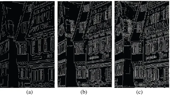
We conducted the following experiments to investigate the effectiveness of the new distributed Canny edge detector that is proposed in this paper. The detection effectiveness of the proposed distributed approach is analyzed by comparing the perceptual significance of its resulting map with the one produced by the original frame-based Canny edge detector, and with the one produced by the algorithm of [4]. Fig. 12(a), Fig. 12(b) and Fig. 12(c) show the edge maps that are obtained for the 512×512House image using the original Canny edge detector, the algorithm of [4], and the proposed algorithm with a 3 × 3 gradient mask and block size of 64. The floating-point Matlab simulation results show that, compared with the traditional Canny edge detector and the algorithm of [4], the algorithm proposed here can yield better edge detection results with few computations. Similar results were obtained for other tested images.
5.2. Fixed-pointMatlab and FPGA Simulation Results
Fig. 13 shows the fixed-point Matlab implementation software result and the FPGA implementation generated result for the 512×512 House image using the proposed distributed Canny edge detector with block size of 64 × 64 and a 3 × 3 gradient mask. The FPGA result is obtained using ModelSim. It is clear that the hardware implementation of our proposed algorithm can successfully detect significant edges and results in edge maps that are similar to the ones that are obtained using the fixed-point Matlab simulation. Furthermore, for a 100 MHz clock rate, the total processing running time using the FPGA implementation is 0.287ms for a 512 × 512 image.
(a) (b) (c)
Figure 12. Floating-point Matlab simulation results for the 512 × 512 House image: (a) Edge map of the original Canny edge detector; (b) Edge map of the algorithm of [4] with a 3×3 gradient mask and a block size of 64; (c) Edge map of our
ISSN(E): 2277-128X, ISBN: 978-93-87396-07-4, pp. 137-144
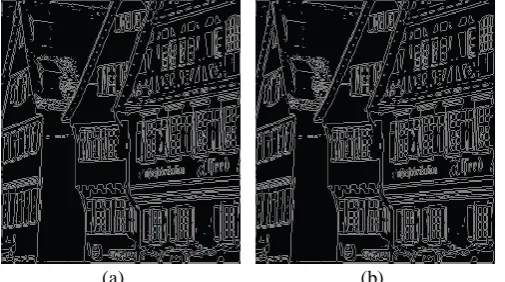
(a) (b)
Figure 13. Fixed-point Matlab software and FPGA hardware simulation results using the proposed algorithm for the 512× 512 House image with a block size of 64 × 64 and a 3 × 3 gradient mask: (a) Edge map of Matlab implementation; (b)
Edge map of FPGA implementation.
6. CONCLUSION
We presented a novel distributed Canny edge detection algorithm that results in a significant speed up without sacrificing the edge detection performance. We proposed a novel non uniform quantized histogram calculation method in order to reduce the computational cost of the hysteresis threshold selection. As a result, the computational cost of the proposed algorithm is very low compared to the original Canny edge detection algorithm. The algorithm is mapped to onto a Xilinx Virtex-5 FPGA platform and tested using ModelSim. It is capable of supporting fast real-time edge detection for images and videos with various spatial and temporal resolutions including full-HD content.
REFERENCES
[1] F. M. Alzahrani and T. Chen, “A real-time edge detector algorithm and VLSI architecture,” Real-Time Imaging,
vol. 3, no. 5, pp. 363 – 78, 1997.
[2] L. Torres, M. Robert, E. Bourennane, and M. Paindavoine, “Implementation of a recursive real time edge detector using retiming techniques,” VLSI, pp. 811 816, Aug. 1995.
[3] D. V. Rao and M. Venkatesan, “An efficient reconfigurable architecture and implementation of edge detection
algorithm using Handle-C,” ITCC, vol. 2, pp. 843 – 847, Apr. 2004.
[4] S. Varadarajan, C. Chakrabarti, L. J. Karam, and J. M. Bauza, “A distributed psycho-visually motivated Canny
edge detector,” IEEE ICASSP, pp. 822 –825, Mar. 2010.
[5] J. Canny, “A computational approach to edge detection,” IEEE Trans. PAMI, vol. 8, no. 6, pp. 679 698, Nov.
1986.
[6] W. He and K. Yuan, “An improved Canny edge detector and its realization on FPGA,” WCICA, pp. 6561 –6564,