Proceedings of the Workshop
Visual Formalisms for Patterns
at VL/HCC 2009
Pattern-Based Layout Specifications for Visual Language Editors
Sonja Maier and Mark Minas
13 pages
Guest Editors: Paolo Bottoni, Esther Guerra, Juan de Lara
Managing Editors: Tiziana Margaria, Julia Padberg, Gabriele Taentzer
Pattern-Based Layout Specifications for Visual Language Editors
Sonja Maier1and Mark Minas2 1[email protected] Institut f¨ur Softwaretechnologie
Universit¨at der Bundeswehr M¨unchen, Germany
2[email protected] Institut f¨ur Softwaretechnologie
Universit¨at der Bundeswehr M¨unchen, Germany
Abstract: When creating an editor for a visual language, a challenging task is the layout specification. Many visual languages, e.g., Ecore diagrams or Petri nets, show similar layout characteristics, and hence reuse of layout behavior should be enabled. For that purpose, we introduce the concept of layout patterns, which en-capsulates certain layout behavior. With the approach, it is possible to combine different layout algorithms, e.g., standard graph drawing algorithms and constraint-based algorithms. In addition, rule-constraint-based layout algorithms may be used that are specifically tailored to the interactive nature of visual language editors.
Keywords:layout specification, meta models, patterns, reuse
1
Introduction
Examples of visual languages are Ecore diagrams [BBM03], Petri nets, Nassi-Shneiderman di-agrams or VEX didi-agrams [CHZ95]. Many visual languages show similar layout characteristics, e.g., Ecore diagrams and Petri nets both have a graph-like structure and allow for nesting of nodes, and hence reuse of layout behavior should be enabled. For different layout characteris-tics, different layout algorithms should be used. E.g., for the graph-like structure of a language, standard graph drawing algorithms, such as force-directed layout or tree layout, should be ap-plied. For other characteristics, constraint-based algorithms are more appropriate. Many layout characteristics require a layout algorithm that is specifically tailored to the interactive nature of diagram editors. Therefore, we added a rule-based layout algorithm, which may be used, too.
In this paper, we introduce layout patterns, which encapsulate certain layout behavior. The idea is to define layout behavior on top of a language-independent, but pattern-specific meta model. The behavior of a layout pattern may either be defined by our rule-based layout algorithm or by any other layout algorithm. This way, a layout pattern provides a reusable and language-independent “solution” for common layout characteristics.
Section 2 introduces Ecore diagrams, the running example used in this paper. The different layout algorithms are presented in Section 3. The concept of layout patterns is presented in
Section 4, and related work is discussed inSection 5. Section 6concludes the paper.
2
Running Example
In the following, we briefly revisit Ecore diagrams. Ecore diagrams are similar to UML class di-agrams. The simplified version considered in this paper consists ofpackages,classes,attributes,
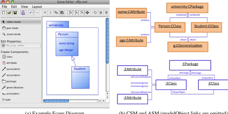
generalizationsandassociations. InFigure 2, an Ecore diagram editor, which was created with the editor generation framework DiaMeta [Min06], is shown.
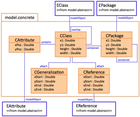
For each visual language editor, a layout meta model (LMM) is specified, on which the layout specification is based on. When a diagram is drawn, the editor instantiates the LMM, obtaining the layout model (LM). The LMM consists of two parts: the abstract syntax meta model (ASMM), representing the languages abstract syntax, and the concrete syntax meta model (CSMM), representing the languages concrete syntax (seeFigure 1). Both meta models are con-nected via the associations namedmodelObject, as denoted inFigure 1b. The CSMM resem-bles all visual components and their spatial relationships, whereas the ASMM is an instance of the diagram language’s meta model that defines the language’s abstract syntax.
(a) Abstract Syntax Meta Model (ASMM)
(b) Concrete Syntax Meta Model (CSMM) together with the connection to the ASMM
Figure 1: Layout Meta Model (LMM)
In the CSMM, each component type is represented by a class, which is connected with its ab-stract syntax counterpart, if available.1In addition, in the CSMM, each meaningful relationship between component types is represented by an association. For Ecore diagrams, the components
package,class,attribute,generalizationandassociationare represented by classes. The relation-shipscontains,contained,overlapandattachare represented by associations. In our example, the ASMM exactly is the Ecore specification [BBM03] and hence is unmodifiable.
Figure 2 shows an Ecore diagram (Figure 2a) together with its CSM and ASM (Figure 2b), wheremodelObjectlinks are omitted. The diagram consists of the following components: the packageuniversity, the two classesPersonandStudent, the two attributesnameof typeStringand
ageof typeIntegerand the generalizationg. The CSM is an instance of the concrete syntax meta model (CSMM), and shows the diagram components together with their spatial relationships. The ASM is an instance of the abstract syntax meta model (ASMM), which conforms to the Ecore specification.
(a) Example Ecore Diagram (b) CSM and ASM (modelObject links are omitted)
Figure 2: Ecore Diagram Editor
3
Layout Algorithms
In the context of diagram editors, usually one of the following layout concepts is chosen: the layouter is written by hand, a standard graph drawing algorithm is applied, or a constraint-based layout algorithm is used. To better support the interactive nature of diagram editors, we ex-tended this list with rule-based layout algorithms. The underlying concept is already known, e.g., interaction dynamics are defined via rules in [BGL06].
With the approach presented in this paper, it is possible to reuse the layout behavior. More details are given inSection 4. Furthermore, all these layout algorithms may be combined. This way, a powerful layouter may be created. Different layout algorithms are combined via the
3.1 Graph Drawing Algorithms
Examples for standard graph drawing algorithms are force-directed layout or layered layout. As graph drawing algorithms tend to be quite complex, it is reasonable to implement them, not to define them on an abstract level. To support interactive diagram drawing, we added several graph drawing algorithms to DiaMeta, following the descriptions of [TDET98,DK08]. The meaningful implementation of these algorithms enables reuse for different visual language editors.
3.2 Constraint-Based Layout Algorithms
A constraint-based algorithm is defined by providing a set of declarative constraints. Many tools that deal with dynamic graph drawing are based on declarative constraints, e.g., [DMW09]. In our approach, the constraints are attached to the LM. A standard constraint solver then com-putes a solution to this constraint satisfaction problem. As constraints are defined on top of the language-specific LM, they need to be redefined for every visual language.
3.3 Rule-Based Layout Algorithms
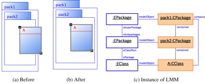
The layout algorithm outlined in this section was introduced in [MMM08a,MMM08b]. To give an overview of the algorithm, we use the simple example shown inFigure 3. When the editor user moves a class, or more generally, changes the diagram, the layout engine is called, and the diagram is updated. In our example, the user has moved classAright (Figure 3a). As classes are not correctly nested after movement, the sizes of both packages (Figure 3b) are updated by the layout engine. This requires the layout engine to run continuously, and to provide immediate feedback about the effect of user changes.
(a) Before (b) After (c) Instance of LMM
Figure 3: Example User Interaction
Layout Rule A layout rule operates on the LM. An example for a layout rule is the rule con-tainment, which takes care of the correct nesting of classes and packages. For each rule, one diagram component is given as input. This usually is a component changed by the user, or a component changed by the layout engine. In the example ofFigure 3, this is classA. Then, other components that are necessary for the layout rule are identified by the layout engine. Here, this is packagepack2. Afterwards, if a rule-specific condition is fulfilled, a rule-specific action is applied. For the rulecontainment, the condition checks if the “package is not large enough”. If this is the case, the action “enlarges the package”.
Specification of a Layout Rule Layout rules are defined on the LMM, and hence they need to be re-specified for every visual language. To define a layout rule, the developer needs to proceed as follows: he has to provide a left-hand side2, a condition (which is optional) and an action. The
left-hand side identifies a component, which has been changed previously, together with the local context needed for layout computation. The condition describes the circumstances, in which an action is applied (e.g., “package is not large enough” as described earlier). The action defines the changes that are actually performed if the condition is fulfilled (e.g., “enlarge the package”).
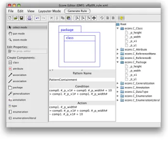
Figure 4: Layout Editor
2 In previous work, the left-hand side has been called pattern. We changed the name to avoid a mix up with the
To allow a more intuitive description, we provide a visual language for layout rule definition. InFigure 4, a screenshot of such an editor for Ecore diagrams is shown. In order to create a layout rule, the editor developer draws a left-hand side using the language’s concrete syntax. In the example, he uses the componentsclassandpackage. The name of the layout rule, a condition and an action are specified below. For specifying conditions and actions, he may access the attributes shown on the right side of the editor, here attributesx1andwidthof the components C_ClassandC_Package.
Strategy The order in which each layout rule is applied to different parts of the diagram usually follows an exact plan, called strategy. In our example the strategycontainmentis used: Starting with the class changed by the user, internal packages are moved and resized first, and surrounding packages are updated afterwards. Besides, the order in which different strategies (and hence their corresponding layout rules) are applied to the diagram has to be specified, too.
Specification of Strategies The definition of strategies is also based on the LMM of the dia-gram language, and hence they need to be redefined for every visual language. For each strategy, a traversal strategy is specified, which is based on the LMM. For the strategycontainment de-scribed earlier, the following is defined: If a class is moved, follow the linkePackage, and retrieve the surrounding package. Apply the rulecontainment to this package, and resize the package accordingly. If the package is changed, follow the linkeSuperPackage, retrieve the surrounding package, and apply the rule containmentto the surrounding package. Besides, it needs to be defined how strategies interact with each other.
3.4 Ecore Editor
The Ecore Editor example uses several layout algorithms. The following rule-based layout algo-rithms are used:
• An algorithm that keeps the minimalsizeof classes and packages.
• An algorithm that takes care of thecontainmentof classes and packages. The algorithm is applied from inside-out.
• An algorithm that aligns attributes as alist. The algorithm is applied from top-to-bottom.
The following graph drawing algorithms are used:
• An algorithm that performsforce-directed layout, which avoids overlapping of classes.
• An algorithm that executes anedge follower. The edge follower makes sure that associa-tions and generalizaassocia-tions stay attached to components.
• An algorithm that performs anedge router, which is responsible for routing associations and generalizations.
4
Pattern-Based Layout Specification
It is reasonable to reuse parts of the layout specification. To enable reuse, we introduce layout patterns that encapsulate certain layout behavior. The term pattern is already known in the context of layout specification [SK03] where the specification of a visual language editor is based on a tree grammar instead of a meta model. In our approach, each layout pattern is based on a language-independant, but pattern-specific meta model. Layout algorithms, graph drawing algorithms and constraint-based algorithms are defined on top of these pattern-specific meta models. In order to apply a layout pattern to a certain visual language, i.e., in order to instantiate the pattern, a mapping between the pattern-specific meta model and the language-specific LMM needs to be defined.
4.1 Meta Models
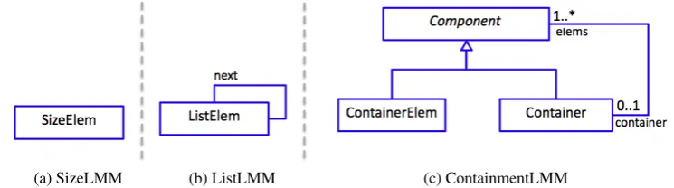
Layout behavior that belongs to a certain layout pattern is defined on top of the corresponding pattern-specific meta model. The meta models SizeLMM, ListLMM and ContainmentLMM, on which the patternsSize, ListandContainmentare based, are shown inFigure 5. The meta model SizeLMM consists of a classSizeElem, which stands for the resizable component. The meta model ListLMM describes a list in terms of many instances of classListElem. The meta model ContainmentLMM consists of a classContainer. Each instance may contain one or moreComponentobjects. AComponentobject is either aContainerEleminstance or a Containerinstance.
(a) SizeLMM (b) ListLMM (c) ContainmentLMM
Figure 5: LMM for Size, List, and Containment
A pattern-specific meta model is an abstraction of the situation in the LMM, meaning that concrete classes in the pattern-specific meta model, that are named roles in the following, cor-respond to classes in the LMM. E.g., the patternContainmenthas the two rolesContainerElem
andContainer. The mapping defines the occurrences of these roles in the LMM.
Meta Model for Graph Drawing Algorithms As we saw in the Ecore Editor example, it is necessary to integrate graph drawing algorithms. To allow for reuse, graph drawing algorithms are integrated as certain patterns, and hence, are based on a pattern-specific meta model. The layout meta model for graphs (GLMM) is shown inFigure 6: A graph consists of several com-ponents. A component is either an edge or a node. An edge has up to three labels and connects two nodes.
4.2 Mappings
Table 1shows four patterns, and enumerates the components of the visual languages Ecore dia-grams and Petri nets, these patterns are applied to. The different roles are identified in the LMM. For Ecore diagrams, the roles are visualized in Figure 7. E.g., for the pattern Containment, classes may have the roleContainerElem, and packages may have the roleContainer.
Pattern Role Ecore diagrams Petri nets
Size SizeElem package & class state & transition
List ListElem attribute —
Containment Container package state ContainerElem class token
Graph Node class state & transition
Edge generalization arrow
Table 1: Mappings of Ecore diagrams & Petri nets.
Usually a pattern is not exactly represented in the meta model of a diagram language. Instead, some variation can be found. E.g., in case of the patternList, anextrelationship is not explicitly contained in the Ecore meta model (Figure 1). The order of attributes is only implicitly defined by the values of the attributeyPosof the classCAttribute. To allow for pattern detection, the LMM must be mapped to a pattern-specific meta model. In case of the patternList, the class CAttribute is mapped to the classListElem. Furthermore, the attributeyPos of the class CAttributeis mapped to the associationnext.
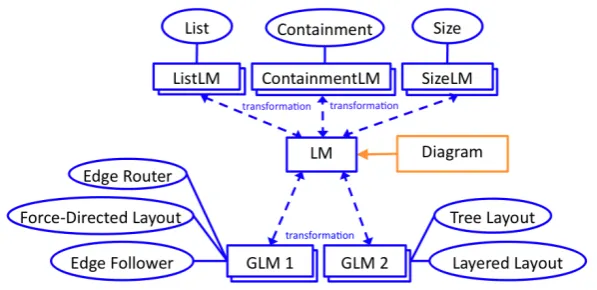
In the Ecore example, for each pattern, a mapping to the corresponding meta model must be defined: the correspondence between the different models can be seen in Figure 8. Here, instances of the meta models of Figure 5 are ListLM, SizeLM, ContainmentLM, GLM 1 and GLM 2. The dashed arrows show the transformations between different models. Every ellipse connected with a rectangle forms a pattern instance, e.g., List together with ListLM, or Edge Router together with GLM 1. Each meta model is instantiated several times: once for each occurrence in the LM. E.g., the patternListis instantiated for eachCClassthat contains one or moreCAttributes.
Figure 8: Correlation of Diagram, LM, Pattern-Specific Models and Patterns
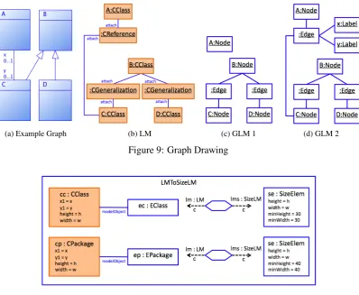
For different graph drawing algorithms, it may be the case that different mappings must be specified. In our example, two mappings between LMM and GLMM are defined. Figure 9
shows an example diagram (Figure 9a) together with its LM (Figure 9b). The corresponding instances of the GLMM can be seen inFigure 9c(GLM 1) andFigure 9d(GLM 2). In GLM 1 classes are mapped to nodes, and generalizations are mapped to edges. In GLM 2, classes are mapped to nodes, and generalizations as well as associations are mapped to edges.
(a) Example Graph (b) LM (c) GLM 1 (d) GLM 2
Figure 9: Graph Drawing
Figure 10: Mapping between LM and SizeLM
Mapping of Attributes In the transformation, attributes of classes in the LM are mapped to attributes of classes in the pattern-specific model. For the pattern Size (Figure 10), the class SizeElemhas the two parametersheightandwidth. Besides, the two optionsminHeight andminWidth can be set. For Ecore diagrams, the patternSize is applied to packages and classes. For packages and classes, heightis mapped to the attribute height, andwidth is mapped to the attributewidth. For packages, the minimal height (minHeight) and the minimal width (minWidth) are set to 40. Analogously, for classes, they are both set to 30:
SizeElem
height = CClass.height, width = CClass.width minHeight = 30, minWidth = 30
SizeElem
height = CPackage.height, width = CPackage.width minHeight = 40, minWidth = 40
4.3 Rule-Based Layout Algorithms
The specification of rule-based layout algorithms is based on the pattern-specific meta model. Layout rules as well as strategies must be specified on this meta model.
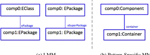
Layout Rules E.g., the layout rules that belong to the layout patternContainmentare based on the meta model ContainmentLM. The “language-specific version” of this pattern consists of two layout rules, whereas the “generalized version” of this pattern consists of one rule. Figure 11
shows the left-hand sides of the layout rules that are based on the LM (Figure 11a) and the left-hand side of the layout rule that is based on the ContainmentLM (Figure 11b).
(a) LMM (b) Pattern-Specific MM
Figure 11: Left-hand side of Layout Rule
Strategies Strategies are also defined on top of the pattern-specific meta model. E.g., the strategy that belongs to the pattern Containmentstarts with the component changed, and then follows the linkcontainer(seeFigure 5), until no more components are available.
4.4 Graph Drawing Algorithms
Graph drawing algorithms are defined on the (predefined) GLMM. The algorithm is either hand-coded or an external graph drawing algorithm. The graph drawing algorithms edge router, edge follower, force-directed layout, tree layout and layered layout all operate on the same GLMM (seeFigure 8).
5
Related Work
We use the concept of layout patterns to encapsulate layout behavior. The termpatternis already known in the context of layout specification [SK03] where the specification of a visual language editor is based on a tree grammar instead of a meta model. We use layout patterns on the basis of meta-model-based visual language editors.
In [Bra01], special aspects are discussed that should be considered when dealing with dynamic graph drawing. In this context, predictable results that preserve the mental map [PS08,MELS95] are favored, instead of high quality layout derived from a standard layout algorithm. As most diagram languages show a graph-like structure, these aspects also apply in our context and are considered in our approach.
Many tools that deal with dynamic graph drawing are based on declarative constraints, e.g., [DMW09]. In our layout algorithm, conditions are defined, which are similar to constraints. In addition, a solution is provided. This way, it is easier to define a target-oriented and, hence, a more pleasant layout behavior. In addition, performance is usually increased since no compli-cated constraint solver must be invoked. However, constraint-based layout algorithms can be combined with rule-based layout algorithms with our approach of layout patterns.
6
Future Work and Conclusions
In this paper, we introduced layout patterns, which encapsulate certain layout behavior. With the approach, it is possible to combine different layout algorithms: Rule-based layout algorithms that are specifically tailored to the interactive nature of visual language editors may be combined with standard graph drawing algorithms and constraint-based layout algorithms. Due to the language-independant nature of layout patterns, reuse of layout behavior is enabled. Layout patterns are defined on top of pattern-specific meta models. To allow for a seamless integration, transforma-tions between the language-specific model and pattern-specific models were introduced. After an editor developer specifies one or more transformations, he may reuse one or more layout patterns. This way, he only needs to specify ”real” language-specific layout behavior.
Currently, transformations between models are written by hand. In future, they will be defined on an abstract level. For that purpose, we currently analyze QVT transformations [OMG05], which offer a visual language for model transformations. As a next step, an “automatic” model mapping would be imaginable, too, as done in [BSG+04]. Besides, the application control is also written by hand. Here, a visual language similar to AGG, Fujaba or PROGRES [FMRS07] is under consideration.
At this point, the combination of different layout patterns is done via the application control, a language-specific control program. Currently, we are working on a more general and formal approach that replaces this part.
Our overall goal is to create a platform, on which new language-specific algorithms that are tailored to interactive diagram drawing may be rapidly created and tested.
Bibliography
[BBM03] F. Budinsky, S. A. Brodsky, E. Merks.Eclipse Modeling Framework. Pearson Ed-ucation, 2003.
Devel-opment of Advanced User Interfaces (MDDAUI ’06). CEUR Workshop Proceed-ings 214. 2006.
[Bra01] J. Branke. Dynamic graph drawing. In Drawing graphs: methods and models. LNCS. Springer, 2001.
[BSG+04] S. Bossung, H. Stoeckle, J. Grundy, R. Amor, J. Hosking. Automated Data Map-ping Specifications via Schema Heuristics and User Interaction. InProc. of the 19th Intl. Conference on Automatic Software Engineering (ASE ’04). Pp. 208–217. IEEE Computer Society, 2004.
[CHZ95] W. Citrin, R. Hall, B. Zorn. Programming with visual expressions. InProc. of the 11th Intl. Symposium on Visual Languages (VL ’95). IEEE Computer Society, 1995.
[DK08] J. Dokulil, J. Katreniakova. Edge Routing with Fixed Node Positions. In Proc. of the 12th Intl. Conference Information Visualisation (IV ’08). IEEE Computer Soci-ety, 2008.
[DMW09] T. Dwyer, K. Marriott, M. Wybrow. Dunnart: A Constraint-Based Network Dia-gram Authoring Tool. In16th Intl. Symposium on Graph Drawing (GD ’08). LNCS. Springer, 2009.
[FMRS07] C. Fuss, C. Mosler, U. Ranger, E. Schultchen. The Jury is still out: A Comparison of AGG, Fujaba, and PROGRES. InProc. of the 6th Intl. Workshop GT-VMT ’07. ECEASST 6. 2007.
[MELS95] K. Misue, P. Eades, W. Lai, K. Sugiyama. Layout Adjustment and the Mental Map.
Journal of Visual Languages & Computing, 1995.
[Min06] M. Minas. Generating Meta-Model-Based Freehand Editors. In Proc. of the 3rd Intl. Workshop on Graph Based Tools. ECEASST 1. 2006.
[MMM08a] S. Maier, S. Mazanek, M. Minas. Layout Specification on the Concrete and Ab-stract Syntax Level of a Diagram Language. InProc. of the 2nd Intl. Workshop on Layout of (Software) Engineering Diagrams (LED 2008). ECEASST 13. 2008.
[MMM08b] S. Maier, S. Mazanek, M. Minas. Visual Specification of Layout. In16th Intl. Sym-posium on Graph Drawing (GD ’08). LNCS. Springer, 2008.
[OMG05] OMG. MOF QVT Final Adopted Specification. Object Modeling Group, 2005.
[PS08] H. C. Purchase, A. Samra. Extremes Are Better: Investigating Mental Map Preser-vation in Dynamic Graphs. InDiagrams ’08. LNCS. Springer, 2008.
[SK03] C. Schmidt, U. Kastens. Implementation of Visual Languages using Pattern-Based Specifications.Software – Practice & Experience33(15), 2003.