TECHNICAL UNIVERSITY OF CLUJ-NAPOCA
ACTA TECHNICA NAPOCENSIS
Series: Applied Mathematics, Mechanics, and Engineering Vol. 60, Issue II, June, 2017
STUDY OF THE OPERATION OF CENTRIFUGAL PUMPS WITH A
MIX-TURE OF AIR AND WATER BY ANALYZING THE VIBRATIONS
Marius STAN
Abstract: The paper addresses the following issues: influence of air-water two-phase mixture over the characteristic of a centrifugal pump; pump vibration in operation at various flow in these conditions; possibilities of using the results of experimental investigations in the numerical simulations for design and training purposes. There are many articles on the operation of centrifugal pumps in the case of the two-phase blend, one of the main contributions made by the author of this research relates to the study of the operation in the two-phase mixture by analyzing the vibrations that are produced.
Key words: influence, two-phase, mixture, investigations, centrifugal pump
1. INTRODUCTION
The paper addresses the following issues:
-Influence of air-water two-phase mixture over the characteristic of centrifugal pump and cavitation aspects in these conditions.
- Pump vibration in operation at various flow conditions and into the cavitation conditions
- Possibilities of using the results of experimental investigations in the numerical simulations.
2. HOW EXPERIMENTS WERE MADE
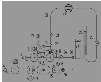
The stand used is formed by a centrifugal pump 3 driven by a DC motor 2. The engine speed can be adjusted by changing the intensity of the current supply with the device 8 (regulating winding resistance of the engine). On the engine shaft 5 is fitted a speed transducer with a display which allows viewing of the engine speed. The pump is linked with the engine through a mechanical coupling. Variation of the pump flow rate is realized with the valve 21. The pump flow is measured using a flow meter 23. The head created by the centrifugal pump is determined
by the pressure difference between the gauges mounted on the suction and discharge of the pump (11 or 12) s. relation (1).
Table 1. Main parameters of the model pump.
Parameters Value
Nominal flow rate 32 m3 /h
Designed head 60 m
Rotating speed 2950 rot/min
Impeller inlet diameter D1 70 mm Impeller outlet diameter D2 130 mm
Impeller outlet width 2 12 mm
Blade number 7
Stages number 10
3. EXPERIMENTAL INVESTIGATION
The experiments were done on the stand from Fig. 1. The parameters of the centrifugal pump used are listed in Table 1.
The characteristics of the centrifugal pump shown in Fig. 2 were obtained measuring the following values: pressure at the outlet of the pump; pressure at the pump inlet; Q pump flow; v vibration speed onto the pump housing; Qa air flow.
Fig. 1. Stand diagram: 1. DC motor actuating compressor; 2. DC motor actuating centrifugal pump; 3. Centrifugal pump; 4. Air compressor; 5-6. Speed transducer; 7-8. Engine speed adjustment; 9. Air filter; 10. Intermediate tank; 11-14. Gauges; 15. Pressure Switch (air pressure adjustment); 16. Flow meter; 17. Vibration transducer (RMS vibration velocity); 18. Speed optical transducer; 19. Registration vibration (Bruel & Kjaer); 20. The one-way valve; 21, 25, 29.
Valves; 22. Pipeline; 23. Flow meter; 24. Water- air mixing head. 26. Air separator; 27. Reservoir.
It was calculated pump head with formula:
(1)
where is water density and gravitational acceleration. To study the influence of the ratio of the air / water, were used more air flows that have been mixed with water in mixing head 24. The comparisons with the normal situation of operation are made in Fig. 2. It was introduced air into the water with following flow values: 1.28 m3s/h; 1.60 m3s/h; 1.92 m3s/h; 2.24 m3s/h; 2.56 m3s/h; 2.88 m3s/h; 3.2 m3s/h; 3.52 m3s/h. The introduction of air into the water, changes the pump characteristic. The hydraulic performance (flow, head, efficiency) are lower. If we follow a point on the initial characteristic it notes that it moves to the left and down (curves noted with C from Fig. 2).
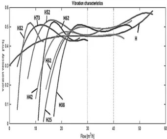
Fig. 2. Changing of the centrifugal pump characteristic at the air insertion into the water: C0 – no air; C1 – 1.28 m3S/h air ; C2 – 1.60 m3
air; H82 (changing of the point from the pump characteristic (Q=14 m3/h; H=82 m water) at different air flows; H73- point (Q=28 m3/h; H=73 m water)); point H62 (Q=31 m3/h; H=62 m water); point H52 (Q=41 m3/h; H=52 m water); point H42 (Q=45 m3/h; H=42 m water)); point H38 (Q=48 m3/h; H= 38 m water); point H32 (Q=50.5 m3/h; H= 32 m water); point H25 (Q=53.5 m3/h; H= 25 m water).
Changes of a point (from pump characteristic) coordinates, with the amount of air are accompanied by modifying the level of vibration.
They are compared with H curve representing the recorded vibrations to normal operation at different flow rates, Fig. 3. For example, the transformation of a point of the pump characteristic (Q = 14 m3 / h; H water = 82 m) in Fig. 3, is shown by the curve H82. That must be read from right to left aiming to present the switch from normal operation. Initially, the vibration velocities are close to the values of normal operation, curve
H. Increasing the amount of air amplifies the vibrations which have a maximum flow rate of 7.5 m3 / h, after it is reduced as a result of the decrease in the flow rate.
This aspect is maintained for transforming the points of the pump characteristic H73, H62, H52 (with high pressure and low flow).
The points on the pump characteristic H42, H38, H32, H25 (with low pressure and high flow) have initial speeds of vibration slightly higher than normal operation.
The vibration level is almost unaffected by flow on the 22- 55 m3 / h flow interval. With the reduction of flow, vibrations decreases rapidly as the amount of air becomes important into the mixture. It acts as a dumper.
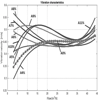
In Figure 4 there are the vibration characteristics for normal operation A0% (no air introduced into the working fluid) and at the introduction of air flow rates (expressed as a percentage of the nominal flow of the pump). The influence occurs in an air flow
rate of at least 4% of the nominal flow of the pump.
Fig. 3. Vibration velocities corresponding of the point modification of the characteristic when introducing different amounts of air into the fluid circulated: H82 vibration velocities corresponding of the point modification (Q = 14 m3 / h, H = 82 m water); H73- point (Q=28 m3/h; H=73 m water)); point H62 (Q=31 m3/h; H=62 m water); point H52 (Q=41 m3/h; H=52 m water); point H42 (Q=45 m3/h; H=42 m water)); point H38 (Q=48 m3/h; H= 38 m water); point H32 (Q=50.5 m3/h; H= 32 m water); point H25 (Q=53.5 m3/h; H= 25 m water).
4. MODEL OF TWO IMMISCIBLE PHASES
For incompressible single-phase fluids at a known intake pressure and temperature, the pressure increment developed by a specific stage is a function of the flow rate and the density.
For air water liquids, the pressure increment of the centrifugal pump stage is directly proportional to the mixture fluid density. In this way, we can define an indirect measurement of the pressure :
Fig. 4. Vibration velocities corresponding to the points of the pump characteristic , at variable amounts of air placed into the fluid: A0% without air; A4% it was introduced an air flow of 1.28 m3S / h; A5% – air flow 1.60 m3
s/h; A6% – air flow 1.92 m3s/h; A7%– air flow 2.24 m3S/h; A8% –air flow 2.56 m3s/h; A9% – air flow 2.88 m3s/h; A10%– air flow 3.2 m3
s/h;A11% –air flow 3.52 m3s/h; pump nominal flow 32 m3/h.
The homogeneous model assumes that centrifugal pump single-phase performance curves can be used to represent two-phase behavior. In this method, the two-phase flow head delivered by the pump is equal to single-phase liquid head at the mixture’s total in-situ flow rate.
The free-air fraction and the total volumetric rate x are adjusted according to the new conditions. The procedure is applied again for the next stage. The pressure increment of each individual stage is calculated with the mixture density.
It can be seen that the procedure once carefully analyzed, does not implement any degradation head. It shifts the points from the water curve according to the total volumetric rate. In this case, increasing the pressure
expressed in terms of a mixing head, which is based on the mixturedensity.
(3)
Where:
- mixturedensity is density for air
- density for water x- total volumetric rate
Alternatively, this head prediction can also be expressed terms of a single-phase water density by multiplying two-phase mixture head by the mixture’s specific gravity. Doing so causes:
(4)
Case study
m3
s/h;A11% –air flow 3.52 m3s/h; pump nominal flow 32 m3/h.
Fig. 6. Comparison between vibration RMS
experimental characteristics and
characteristics obtained by model of two immiscible phases experimental method. Series 1: A0% without air; A4% and series 2-9 it was introduced an air flow of 1.28 m3S / h; A5% – air flow 1.60 m3s/h; A6% – air flow 1.92 m3
s/h; A7%– air flow 2.24 m3S/h; A8% – air flow 2.56 m3s/h; A9% – air flow 2.88
m3
s/h; A10%– air flow 3.2 m3s/h;A11% –air flow 3.52 m3s/h; pump nominal flow 32 m3/h.
It is noted that satisfactory results are obtained at flow rates above 25 m3/h, but at a quantity of air ranging from 4% to 7%. If the amount of air is increasing the correction method do not provide acceptable results. In the field of small flows (less than 25 m3/h) introducing a quantity of air, sharply changes the characteristics of the pump, while the correction method indicates a very small change. In this case, the correction method gives results which cannot be used in practice.
5. CONCLUSIONS
The hydraulic performance (flow, head, efficiency) are lower Figure 3, Figure 6. However does not exist a model of transformation of the pump.
The introduction of air into the water, changes the pump characteristic linked to the air flow introduced into the pump Figure 3.
Changes of a point (from the pump characteristic) coordinates, with the amount of air are accompanied by modifying the level of vibration. The operation at the flow rates that differ from Qn (in particular under 0.6 of Qn and more than 1.2 of Qn), with the amount of air more than 5% of Qn is characterized by the velocities of vibration up to 60% higher compared to the values of normal operation Fig. 5, Fig. 6.
The analytical method of correction cannot be used in practice. Differences
between the experimental curves
corresponding air-water mixture and those determined by the method of correction are important.
Experimental results on the pump characteristic with two-phase mixtures can be used in numerical models to predict the behavior of centrifugal pumps for training and design purposes.
[1] Bratu Ch. Two phase pump transient behavior, SPE 30660, SPE Annual Technical Conference & Exhibition Dallas U.S.A., 22-25 October, 1995. [2] Bratu, Ch. Rotodynamic Two-Phase Pump
Performances, SPE 28516, 69th. Annual Technical Conference, New Orleans 1994. [3] Dobre A. D. N. Contribution to the study gas-liquid two-phase flows in pipes, PhD Thesis, Construction Tehnical University Bucharest, 2014.
[4] Pana I. Aspects Regarding Noise in the
Pumping Stations, Petroleum-Gas
University of Ploiesti Bulletin, Technical Series, ISSN 1224-8495, vol. LX, p. 37-45, nr: 1/2008.
[5] Pana I. Using Simhydraulics in Didactic Applications, Petroleum-Gas University of Ploiesti Bulletin, Technical Series, ISSN 1224-8495, vol. LIX, p. 25-32, nr:1/2007.
[6] Patemost, G.M., Bannwart A.C., Estevam E. Experimental study of a centrifugal pump handling viscous fluid and two phase flow, SPE 165028, SPE Production and Operation, May 2015, p.146-155. [7] Pessoa R., Prado M. Two phase flow
performance for electrical Submersible pump stages, SPE 81910, SPE Production and Facilities, February 2003, p. 13-27
Studiul funcționării pompelor de centrifugă cu amestec de aer si apa prin analiza vibratiilor produse
Lucrarea abordează următoarele aspecte: influența amestecului de două faze aer-apă asupra
caracteristicilor unei pompe centrifuge; Studiul vibrațiilor pompei în funcționare la diferite debite în aceste condiții; Posibilitățile de utilizare a rezultatelor investigațiilor experimentale la simulările
numerice în scopuri de proiectare și instruire. Există multe articole cu privire la funcționarea
pompelor centrifuge în cazul amestecului de doua faze, una dintre principalele contributii aduse de autorul acestor cercetări se referă la studierea operației în cadrul amestecului în două faze prin
analiza vibratiilor care se produc.
Marius Stan, Asociate profesor, University of Petroleum–Gas Ploiesti, Department: Mechanical Engineering, [email protected], Brumărelelor, nr. 6, Ploiești, 100680, ROMANIA,