The information provided in this documentation contains general descriptions and/or technical characteristics of the performance of the products contained herein. This documentation is not intended as a substitute for and is not to be used for determining suitability or reliability of these products for specific user applications. It is the duty of any such user or integrator to perform the appropriate and complete risk analysis, evaluation and testing of the products with respect to the relevant specific application or use thereof. Neither Schneider Electric Industries SAS nor any of its affiliates or subsidiaries shall be responsible or liable for misuse of the information contained herein.
Product data sheet
Characteristics
ATV320U07N4C
variable speed drive, ATV320, 0.75 kW, 380…
Product availability: Stock - Normally stocked in distribution facility
Main
Range of product Altivar Machine ATV320 Product or component
type Variable speed drive Product specific
applica-tion Complex machines
Device short name ATV320
Product destination Synchronous motors Asynchronous motors Format of the control
block Compact
EMC filter Class C2 EMC filter integrated IP degree of protection IP20 IEC 61800-5-1
IP20 IEC 60529 Degree of protection With conformity kit) Type of cooling Fan
Phase 3 phase
[Us] rated supply
volt-age 380...500 V - 15...10 % Supply frequency 50...60 Hz - 5...5 % Motor power kW 0.75 kW heavy duty Maximum Horse Power
Rating 1.0 hp heavy duty Line current 3.2 A 380 V heavy duty)
2.4 A 500 V heavy duty) Prospective line Isc 5 kA
Apparent power 2.1 kVA 500 V heavy duty) Continuous output
cur-rent 2.3 A 4 kHz heavy duty Maximum transient
cur-rent 3.5 A 60 s heavy duty) Power range 0.75...1.1 kW Asynchronous motor
control profile Voltage/Frequency ratio, 5 pointsFlux vector control without sensor, standard Voltage/Frequency ratio - Energy Saving, quadratic U/f
Flux vector control without sensor - Energy Saving Voltage/frequency ratio, 2 points
Synchronous motor
control profile Vector control without sensor Speed drive output
fre-quency 0.1…599 Hz
Nominal switching
fre-quency 4 kHz
Switching frequency 2...16 kHz adjustable 4...16 kHz with derating factor Safety function STO (safe torque off) SIL 3
SLS (safe limited speed) SS1 (safe stop 1)
SMS (safe maximum speed) GDL (guard door locking) Communication port
protocol Modbus serialCANopen Optional communication
modules Communication module, CANopen daisy chain RJ45Communication module, CANopen SUB-D 9 Communication module, CANopen open style termi-nal block
Communication module, EtherCAT RJ45 Communication module, DeviceNet Communication module, Ethernet/IP Communication module, Profibus DP V1 Communication module, Profinet
Complementary
Variant Standard version
Output voltage <= power supply voltage Permissible temporary current boost 1.5 x In 60 s heavy duty)
Speed range 1…100 asynchronous motor in open-loop mode Speed accuracy +/- 10 % of nominal slip 0.2 Tn to Tn
Torque accuracy +/- 15 %
Transient overtorque 170…200 % of nominal motor torque Braking torque <= 170 % 60 s with braking resistor Regulation loop Adjustable PID regulator
Motor slip compensation Automatic whatever the load Adjustable 0...300 %
Not available in voltage/frequency ratio (2 or 5 points) Acceleration and deceleration ramps Linear
U S CUS
Ramp switching
Acceleration/Deceleration ramp adaptation
Acceleration/deceleration automatic stop with DC injection Braking to standstill By DC injection
Protection type Input phase breaks drive
Overcurrent between output phases and earth drive Overheating protection drive
Short-circuit between motor phases drive Thermal protection drive
Frequency resolution Display unit 0.1 Hz Analog input 0.012/50 Hz
Electrical connection Screw terminal 0.5...1.5 mm², AWG 20...AWG 16 control)
Screw terminal 2.5...6 mm², AWG 14...AWG 10 motor/braking resistor) Screw terminal 2.5...6 mm², AWG 14...AWG 10 power supply) Connector type 1 RJ45 on terminal)Modbus/CANopen
Physical interface 2-wire RS 485 Modbus serial/CANopen
Transmission frame RTU Modbus serial
Transmission rate 4.8, 9.6, 19.2, 38.4 kbit/s Modbus serial
50 kbps, 125 kbps, 250 kbps, 500 kbps, 1 Mbps CANopen Data format 8 bits, configurable odd, even or no parity Modbus serial Type of polarization No impedance Modbus serial
Number of addresses 1…127 CANopen
1…247 Modbus serial
Method of access Slave CANopen
Supply Internal supply for reference potentiometer (1 to 10 kOhm) 10.5 V DC +/- 5 %, <10 mA overload and short-circuit protection
Local signalling CANopen run 1 LED green)
CANopen error 1 LED red) Drive fault 1 LED red)
Width 4.13 in (105.0 mm)
Height 5.59 in (142.0 mm)
Depth 6.22 in (158.0 mm)
Net weight 2.65 lb(US) (1.2 kg)
Analogue input number 3
Analogue input type AI1 voltage 0...10 V DC 30000 Ohm 10 bits
AI2 bipolar differential voltage +/- 10 V DC 30000 Ohm 10 bits
AI3 current 0...20 mA (or 4-20 mA, x-20 mA, 20-x mA or other patterns by configu-ration) 250 Ohm 10 bits
Discrete input number 7
Discrete input type Programmable (sink/source) DI1...DI4)24...30 V DC level 1 PLC Programmable as pulse input 20 kpps DI5)24...30 V DC level 1 PLC Switch-configurable PTC probe DI6)24...30 V DC
Safe torque off STO)24...30 V DC - 1500 Ohm Discrete input logic Negative logic (sink) DI1...DI6), > 19 V, < 13 V Positive logic (source) DI1...DI6), < 5 V, > 11 V
Analogue output type AQ1 software-configurable current 0...20 mA 800 Ohm 10 bits AQ1 software-configurable voltage 0...10 V 470 Ohm 10 bits Sampling duration 2 Ms AI1, AI2, AI3) - analog input
2 ms AQ1) - analog output
Accuracy +/- 0.2 % AI1, AI2, AI3 for a temperature of -10...60 °C analog input +/- 0.5 % AI1, AI2, AI3 for a temperature of 25 °C analog input +/- 1 % AQ1 for a temperature of 25 °C analog output +/- 2 % AQ1 for a temperature of -10...60 °C analog output Linearity error AI1, AI2, AI3 +/- 0.2...0.5 % of maximum value analog input
AQ1 +/- 0.3 % analog output
Discrete output number 3
Discrete output type Configurable relay logic R1A, R1B, R1C) NO/NC - 100000 cycles Configurable relay logic R2A, R2B) NO - 100000 cycles
Logic LO)
Refresh time Logic input DI1...DI6)8 ms +/- 0.7 ms) Relay output R1A, R1B, R1C)2 ms Relay output R2A, R2C)2 ms Minimum switching current Relay output R1, R2 5 mA 24 V DC
Maximum switching current Relay output R1 resistive, cos phi = 1 3 A 250 V AC Relay output R1 resistive, cos phi = 1 4 A 30 V DC Relay output R1, R2 inductive, cos phi = 0.4 2 A 250 V AC Relay output R1, R2 inductive, cos phi = 0.4 2 A 30 V DC Relay output R2 resistive, cos phi = 1 5 A 250 V AC Relay output R2 resistive, cos phi = 1 5 A 30 V DC
Specific application Machinery
Variable speed drive application selection Self erecting Hoisting Carousel Material handling Conveyor Material handling Lifting platfrom Material handling
Palletizers - medium performance Material handling Transfer table Material handling
Turn table Material handling
Cutting - medium accuracy Material working (wood, ceramic, stone, pvc, metal) Drilling Material working (wood, ceramic, stone, pvc, metal)
Saw Material working (wood, ceramic, stone, pvc, metal) Bagging Packaging
Feed conveyor low performance Packaging Filling bottles - intermittent operation Packaging Linear labeling Packaging
Other application Packaging Stretching wrapping Packaging Tray take Packaging
Knitting Textile
Printing machines Textile Spinning Textile Car Washing machines
Other application Washing machines Standard crane - travelling or trolley Hoisting Motor power range 0.75…1.1 kW 380…500 V 3 phase
Motor starter type Variable speed drive
Environment
Isolation Between power and control terminals
Insulation resistance > 1 MOhm 500 V DC for 1 minute to earth
Noise level 51 dB 86/188/EEC
Power dissipation in W Fan 38.5 W 380 V 4 kHz Volume of cooling air 4755.18 Gal/hr(US) (18.0 m3/h) Operating position Vertical +/- 10 degree
Electromagnetic compatibility 1.2/50 µs - 8/20 µs surge immunity test level 3 IEC 61000-4-5 Conducted radio-frequency immunity test level 3 IEC 61000-4-6 Electrical fast transient/burst immunity test level 4 IEC 61000-4-4 Electrostatic discharge immunity test level 3 IEC 61000-4-2
Radiated radio-frequency electromagnetic field immunity test level 3 IEC 61000-4-3
Voltage dips and interruptions immunity test IEC 61000-4-11
Pollution degree 2 EN/IEC 61800-5-1
3 EN/IEC 61800-5-1
Vibration resistance 1 gn 13…200 Hz)EN/IEC 60068-2-6
Shock resistance 15 gn 11 ms EN/IEC 60068-2-27
Relative humidity 5…95 % without condensation IEC 60068-2-3 5…95 % without dripping water IEC 60068-2-3 Ambient air temperature for operation 14…122 °F (-10…50 °C) without
122…140 °F (50…60 °C) with derating factor Ambient air temperature for storage -13…158 °F (-25…70 °C)
Operating altitude <= 3280.84 ft (1000 m) without
3280.84...9842.52 ft (1000...3000 m) with current derating 1 % per 100 m Environmental characteristic Chemical pollution resistance class 3C3 EN/IEC 60721-3-3
Dust pollution resistance class 3S2 EN/IEC 60721-3-3
Standards EN/IEC 61800-3
Environment 1 category C2 EN/IEC 61800-3 Environment 2 category C3 EN/IEC 61800-3 EN/IEC 61800-5-1
IEC 61000-3-12 IEC 60721-3 IEC 61508 IEC 13849-1
Product certifications CE
ATEX NOM EAC RCM KC Marking CE ATEX UL CSA EAC RCM KC
Ordering and shipping details
Category 22152 - ATV320/ATV312/ATV32 (.25 THRU 7.5HP)
Discount Schedule CP4B
GTIN 00785901622666
Package weight(Lbs) 1.69 kg (3.72 lb(US))
Returnability Yes
Country of origin ID
Offer Sustainability
Sustainable offer status Green Premium product
REACh Regulation REACh Declaration
EU RoHS Directive Pro-active compliance (Product out of EU RoHS legal scope) EU RoHS
Decla-ration
Mercury free Yes
RoHS exemption information Yes
China RoHS Regulation China RoHS Declaration Environmental Disclosure Product Environmental Profile Circularity Profile End Of Life Information
WEEE The product must be disposed on European Union markets following specific waste collection and never end up in rubbish bins.
Product data sheet
Dimensions Drawings
ATV320U07N4C
Dimensions
Product data sheet
Mounting and Clearance
ATV320U07N4C
Mounting Types
Mounting Type A: Individual with Ventilation Cover
Only Possible at Ambient Temperature Less or Equal to 50 °C (122 °F)
Mounting Type B: Side by Side, Ventilation Cover Removed
Mounting Type C: Individual, Ventilation Cover Removed
Product data sheet
Connections and Schema
ATV320U07N4C
Connection Diagrams
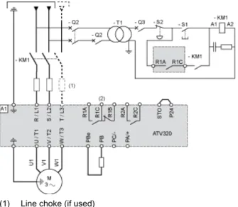
Diagram with Line Contactor
Connection diagrams conforming to standards ISO13849 category 1 and IEC/EN 61508 capacity SIL1, stopping category 0 in accordance with standard IEC/EN 60204-1.
(1) Line choke (if used)
(2) Fault relay contacts, for remote signaling of drive status
Diagram with Switch Disconnect
Connection diagrams conforming to standards EN 954-1 category 1 and IEC/EN 61508 capacity SIL1, stopping category 0 in accordance with standard IEC/EN 60204-1.
(1) Line choke (if used)
(2) Fault relay contacts, for remote signaling of drive status
(1) Analog output (2) Analog inputs
(3) Reference potentiometer (10 kOhm maxi) (4) Digital inputs
Digital Inputs Wiring
The logic input switch (SW1) is used to adapt the operation of the logic inputs to the technology of the programmable controller outputs. Switch SW1 set to “Source” position and use of the output power supply for the DIs.
Switch SW1 set to “Source” position and use of an external power supply for the DIs.
Product data sheet
Performance Curves
ATV320U07N4C
Derating Curves
40 °C (104 °F) - Mounting type A, B and C 50 °C (122 °F) - Mounting type A, B and C 60 °C (140 °F) - Mounting type B and C In : Nominal Drive Current