SENSORY PERCEPTUAL METRICS: DESIGN AND APPLICATION OF BIOLOGICALLY BASED METHODS FOR THE ASSESSMENT OF SYSTEMIC CORTICAL ALTERATIONS
Jameson Holden
A dissertation submitted to the faculty of the University of North Carolina at Chapel Hill in partial fulfillment of the requirements for the degree of Doctor of Philosophy in the
Department of Biomedical Engineering.
Chapel Hill 2013
ABSTRACT
Jameson Holden: Sensory Perceptual Metrics: Design and Application of Biologically Based Methods for the Assessment of Systemic Cortical Alterations
(Under the direction of Mark A Tommerdahl)
A large number of neurological disorders (neurodegenerative, neurodevelopmental or trauma induced) are difficult to diagnose or assess, thus limiting treatment efficacy.
Existing solutions and products attempting to fill this gap are costly, extremely slow, often invasive, and in many cases fail to definitively (and quantitatively) diagnose or assess treatment. Our innovative low-cost sensory testing device and accompanying software package can be used to non-invasively assess the central nervous system (CNS) health status in minutes for numerous patient populations. The somatosensory system is ideally suited for the design of a CNS diagnostic system. First, the organization of the system is such that adjacent skin regions project to adjacent cortical regions (i.e., it is somatotopic). Second, ambient environmental noise in the system can be easily controlled (i.e., it is less likely that a patient will be exposed to distracting tactile input than auditory or visual input). Third, the somatosensory system is the only sensory system that is highly integrated with the pain system, and this is often an important aspect of a patient‘s diagnosis. The
diagnostic system delivers a battery of somatosensory-based tests that are conducted rapidly, much like an eye exam with verbal feedback. Neuro-adaptation, functional
connectivity (e.g. cortical synchronization), and feed-forward inhibition are just a few of the cortical mechanisms that can be quantified using somatosensory testing protocols. Many of these protocols leverage tactile illusions which act as confounds on top of a basic
TABLE OF CONTENTS
ABSTRACT ... iii
LIST OF FIGURES ... viii
LIST OF ABBREVIATIONS ... x
CHAPTER 1: INTRODUCTION ... 1
CHAPTER 2: CM4: A FOUR-POINT VCA BASED VIBROTACTILE STIMULATOR1 ... 5
Overview ... 5
Introduction ... 6
Methods ... 7
Hardware. ... 7
Software ... 10
Protocols ... 11
Subjects ... 11
Experimental Procedure ... 11
Finger Agnosia Protocol ... 12
Analysis... 14
Auditory Cue Analysis ... 14
Results ... 15
Discussion ... 17
CHAPTER 3: CM3: A FOUR-POINT PIEZOELECTRIC BASED MRI/MEG COMPATIBLE VIBROTACTILE STIMULATOR1 ... 21
Overview ... 21
Methods ... 25
Hardware ... 25
Software ... 28
Protocols ... 29
Subjects ... 29
Experimental Procedure – TOJ with and without background noise ... 29
Temporal Order Judgement, without (TOJs) and with carrier (TOJc) stimulus ... 30
Results ... 31
MRI recording results ... 33
Discussion ... 33
CHAPTER 4: VIBROTACTILE STIMULATOR SOFTWARE INTERFACE ... 37
Device Driver Library ... 42
Common Plugin Library ... 44
Shell Application ... 49
Database ... 50
CHAPTER 5: APPLICATIONS ... 53
Using Illusions to Quantify CNS Information Processing Capacity ... 53
Percepts of Tactile Stimuli Can Be Measured Quantitatively. ... 54
Impacts of Illusory Conditioning on Sensory Percepts Are Baseline Independent. ... 55
Sensory Metric Category #1: Neuro-adaptation ... 55
Baseline Amplitude Discrimination ... 55
Neuro-adaptation ... 57
Sensory Metric Category #2: Functional Connectivity ... 58
Temporal Order Judgement ... 58
Functional Connectivity ... 60
Sensory Metric Category #3: Duration-Intensity Interactions. ... 61
Duration Intensity Interactions ... 62
Sensory Metric Category #4: Feed Forward Inhibition. ... 63
Stimulus Detection Threshold ... 63
Feed Forward Inhibition ... 64
Enhancing Sensory Performance to Derive Measures of CNS Performance. ... 65
Analysis and Application ... 68
CHAPTER 6: FUTURE DIRECTIONS... 70
Reduce Reliance on 3rd Party Data Acquisition ... 70
Therapeutic Potential ... 72
Possibilities for Use with Large Non-Primate Mammals ... 76
Optimal Location for Stimulation ... 77
Necessary Device Modifications ... 81
Test and Training Paradigms ... 83
Possible Experimental Pitfalls ... 84
APPENDIX 4.1: CLASS DIAGRAM FOR DEVICE DRIVER LIBRARY ... 86
APPENDIX 4.2: CLASS DIAGRAM FOR SHELL AND PLUGIN LIBRARY ... 87
APPENDIX 4.3: SAMPLE XML PROTOCOL BATTERY ... 104
LIST OF FIGURES
1.
Figure 2.1: Four Site Vibrotactile Stimulator ... 8Figure 2.2: Schematics of Finger Agnosia Protocols ... 13
Figure 2.3: Average Percent Accuracy the Effect of Conditioning Stimuli on the Finger Agnosia Task ... 15
Figure 2.4: Average Percent Inaccuracy on Finger Agnosia with 100 μm Conditioning Stimuli ... 17
Figure 3.1: Four Site Vibrotactile Stimulator ... 26
Figure 3.2: Impact of Conditioning Stimulus on TOJ Performance ... 32
Figure 4.1: Optical Sensor Readings Verify Sinusoid Generation ... 38
Figure 4.2: FFT of Measured Sinusoid in Figure 1 ... 38
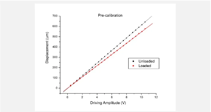
Figure 4.3: Pre-calibration Driving Amplitude Discrepancy ... 39
Figure 4.4: VCA Calibration Application ... 40
Figure 4.5: Abbreviated Driver Library Class Diagram ... 43
Figure 4.6: Abbreviated Class Diagram of Common Plugin Interface Library ... 45
Figure 4.7: Example Plugin ... 48
Figure 4.8: Abbreviated Class Diagram of Shell Application ... 49
Figure 4.9: SQL Database Diagram for Quantitative Assessments ... 51
Figure 4.10 Data Flow Diagram ... 52
Figure 5.1: Example of Visual Illusion ... 54
Figure 5.2: Diagram of Amplitude Discrimination ... 56
Figure 5.3: Task improvement for impaired populations ... 56
Figure 5.4: Extracellular response for 3s stimulation ... 57
Figure 5.5: Pre/Post application of topical GABA agonist ... 58
Figure 5.7: TOJ performance in impaired populations ... 59
Figure 5.8: Synchronization via sub-threshold stimuli ... 60
Figure 5.9: Diagram of Duration Discrimination ... 61
Figure 5.10: Duration Discrimination in impaired populations ... 62
Figure 5.11: Effects of Amplitude modulation on OIS time-course. ... 62
Figure 5.12: Diagram of Detection Threshold ... 64
Figure 5.13: Static vs Dynamic Detection Thresholds across age groups ... 64
Figure 5.14: Static vs Dynamic Ratio in impaired populations ... 64
Figure 5.15: Applications Can Also Enhance Healthy Performance ... 66
Figure 5.16: Cortical Contrast Enhancement Aids Perceptual Differentiation ... 67
Figure 5.17: Cortical Metrics are Make it Difficult to Feign Impairment ... 67
Figure 5.18: 3D Plot Demonstrating Separation Between Control and Impaired Populations ... 68
Figure 5.19: PCA Plot with 5 Paramters Differentiates Subject Populations ... 69
Figure 6.1: Functional MRI Activation in Patients with CTS ... 74
Figure 6.2: Cortical Digit Separation in SI for Patients with CTS ... 75
Figure 6.3: Porcine Rostral Receptive Field Mapping ... 78
LIST OF ABBREVIATIONS
MVC Model View Controller ADC Analog to Digital Converter AFC Alternative Forced Choice AWG American Wire Gauge
BP Blood Pressure
CAD Computer-Aided Design CNC Computer Numerical Control CNS Central Nervous System CTS Carpal Tunnel Syndrome DAC Digital to Analog Converter DAL Database Abstraction Layer DAQ Data Acquisition
DC Direct Current DL Difference Limen DSP Digital Signal Processor DXM Dextromethorphan
FDM Fusion Deposition Modeling FFT Fast Fourier Transform
fMRI Functional Magnetic Resonance Imaging FPU Floating Point Unit
MCRP Motor-Related Cortical Potential MEG Magnetoencephalography MRI Magnetic Resonance Imaging MSIL Microsoft Intermediate Language MVC Model-View-Controller
NMDA N-methyl-D-aspartate
OOP Object-Oriented Programming
PC Personal Computer
PCA Principal Component Analysis PCI Peripheral Component Interconnect PID Proportional-Integral-Derivative
RDBMS Relational Database Management System RF Receptive Field
RMS Root Mean Square
SPI Serial-Peripheral Interface SPS Samples Per Second
SQL Structured Query Language SVM Support Vector Machine TBI Traumatic Brain Injury
TMJD Temporomandibular Joint Disorder TOJ Temporal Order Judgement
USB Universal Serial Bus VCA Voice Coil Actuator
VVS Vulvar Vestibulitis Syndrome
WCAG Web Content Accessibility Guidelines
WM Working Memory
CHAPTER 1: INTRODUCTION
There is currently a significant gap that exists between fundamental neuroscience research and translation of the findings of that research into everyday practice.
Experimental findings at the genetic, cellular, molecular and systems level often take a fairly long and often circuitous route to make an impact on a particular neurological disease or disorder. Additionally, there is no standard, reliable, cost-effective paradigm or
methodology for assessing the degree to which the central nervous system (CNS) is impacted by any of a given number of neurological disorders. A large number of
neurological disorders (neurodegenerative, neurodevelopmental, pharmacological or trauma induced) are difficult to diagnose or assess, thus limiting treatment efficacy. Current
informed decision about a patient‘s diagnosis and/or about efficacy of treatment. An additional goal of the original work was to bridge the neuroscientific gap at the systems level of study by developing standardized sensory measures that could be not only utilized in clinical or clinical research settings, but could be directly correlated with the observations obtained directly from high resolution laboratory animal experimentation.
The tactile diagnostic system that was developed was conceptually designed to investigate differences in cortical information processing strategies between people with autism and people without. Thus, a number of tests specifically target diminished capacities known to exist in autism from genotypic, physiological and anatomical studies. The
question that were subsequently addressed is whether or not the strategy that was devised for investigating a population with a neurodevelopmental disorder can be broadly applied to a number of neurological disorders. In other words, it is considered that the changes manifested by the neurodevelopmental disorder autism to be systemic, in that large scale alterations in cortical processing are impacted because of changes that occur throughout the cortex. If systemic cortical alterations occur in other neurological disorders, could they also be detected in the same manner?
Proof-of-concept studies in a number of clinical research areas demonstrated that these newly developed metrics were sensitive to systemic cortical alterations. For example, a metric of central adaptation was obtained in a large cohort of subjects from multiple populations, and it was found that this metric in all of these subject populations was significantly impacted. This is not particularly surprising, as a number of cortical
concussion/TBI (white matter damage; neuron-glial interactions), pharmacological manipulation (DXM blocks NMDA receptors; Folger et al, 2008), and chronic pain (fibromyalgia, VVS, migraine, IBS and TMJD -often treated with GABA agonists and/or NMDA antagonists). One question that emerges from this data is that most of these neurological disorders result in some type of altered central sensitization, no matter what the cause – whether it be neurodevelopmental, neurodegenerative, pharmacological or trauma induced – in which there is a significant change in the balance between excitation and inhibition.
The scientific aim of the dissertation work was to determine if sensory perceptual metrics, similar to those that were used to successfully distinguish subjects with autism from healthy control populations, could be used to reliably distinguish – on an individual basis – subjects with neurological disorders that are not neurodevelopmental in nature. Towards that goal, subjects from two broad categories of neurological disorders - chronic pain and trauma induced systemic alterations – were targeted. The engineering aim – and the most significant part of this dissertation – was the hardware and software development of a low cost, portable vibrotactile stimulator that could be widely distributed and used virtually anywhere. Widespread distribution of the device allowed for a large number of proof-of-concept studies in a diverse spectrum of neurological disorders to be feasible.
The potential impact of this work is highly significant for multiple communities. A simple, fast, non-invasive, cost-effective means for assessing CNS health that could be utilized by health care providers could have an overwhelming impact. To date, there are no standardized, quantitative measures for assessing altered central sensitization. The
CHAPTER 2: CM4: A FOUR-POINT VCA BASED VIBROTACTILE STIMULATOR1 Overview
Current methods for applying multi-site vibratory stimuli to the skin typically involve the use of multiple, individual vibrotactile stimulators. Limitations of such an arrangement include difficulty with both positioning the stimuli as well as ensuring that stimuli are delivered in a synchronized and deliberate manner. Previously, we reported a two-site tactile stimulator that was developed in order to solve these problems (Tannan et al., 2007a). Due to both the success of that novel stimulator and the limitations that were inherent in that device, we designed and fabricated a four-site stimulator that provides a number of advantages over the previous version. First, the device can stimulate four independent skin sites and is primarily designed for stimulating the digit tips. Second, the positioning of the probe tips has been re-designed to provide better ergonomic hand
placement. Third, the device is much more portable than the previously-reported stimulator. Fourth, the stimulator head has a much smaller footprint on the table or surface where it resides. To demonstrate the capacity of the device for delivering tactile stimulation at four independent sites, a finger agnosia protocol, in the presence and absence of conditioning stimuli, was conducted on seventeen healthy control subjects. The study demonstrated that with increasing amplitudes of vibrotactile conditioning stimuli concurrent with the agnosia test, inaccuracies of digit identification increased, particularly at digits D3 and D4. The results are consistent with prior studies (Tommerdahl et al. 2007) that implicated
synchronization of adjacent and near-adjacent cortical ensembles with conditioning stimuli in impacting TOJ performance.
_______________________
1This chapter previous appearted in the Journal of Neuroscience Methods. The original citiation is as follows:
Introduction
For the past several years, our research group has been working towards the
development of a portable tactile stimulator that could effectively be used to study changes in sensory information processing in clinical and clinical research venues across a diverse spectrum of neurological disorders. Thus far, we have gone through several iterations in the development of this stimulator. The first prototype of the device (Tannan et al., 2005a) was used to demonstrate changes in spatial acuity with repetitive stimulation. A subsequent report described that this change did not occur with individuals with autism, strongly suggesting a lower-than-normal inhibitory response (Tommerdahl et al., 2007a). A second iteration of the device (Tannan et al., 2007a) was much more portable as well as more robust and reliable in its ability to deliver well-controlled vibrotactile stimuli to the skin. The device proved extremely useful, and a number of studies were conducted with it that
vibrotactile stimuli to four fingers: the index (D2), middle (D3), ring (D4), and little (D5) fingers. The utility of this device has been recently reported in a paper that reported phenotypic differences within a spectrum of patients with vulvodynia (Zhang et al., 2011), and in a paper that describes its utility for describing phenotypic differences within the autism spectrum via modulating vibrotactile stimuli (i.e., sinusoidal stimuli that dynamically change in amplitude), but the device itself, as well as a demonstration of its capability to deliver four-digit protocols, has not been fully described, which is the purpose of this report. In a subsequent paper, a magnet-compatible version of this device will be reported.
Methods
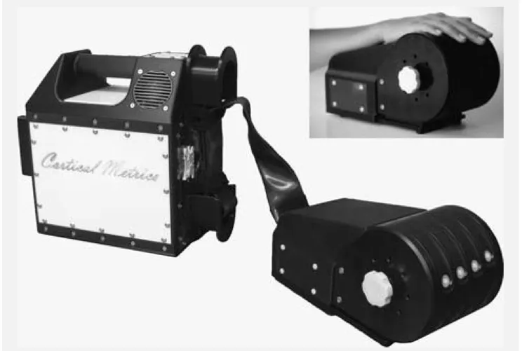
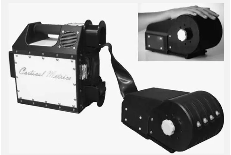
Hardware. The Cortical Metrics (CM-4; see Figure 1) stimulator was developed in our
laboratories for use in series of experiments such as those described in this report. The system was designed using state-of-the-art rapid manufacturing technology to allow multiple identical systems to be built and used in different locations. Also, the use of rapid manufacturing permitted very rapid design evolution, thereby potentiating the production of special fixtures and changes to geometry as needed for special applications. The device consists of two separate parts: the main body and a detachable head unit. The flat plates of all exterior housing and other components of approximately planar geometry are direct manufactured using laser-machined 6 mm acrylic sheet, cut on a 120 Watt CO2 laser engraving system, model number X660 (Universal Laser Systems, Scottsdale, AZ). The more complex housing and internal mechanism components are direct manufactured from ABS plus, by fusion deposition modeling (FDM) on a StrataSys Dimension bst 1200es (StrataSys, Inc., Eden Prairie, MN). The cylindrical trays forming the disks of the head unit are CNC machined from 1" thick Acetal (Delrin) plate. All housing and mechanism
Figure 2.1: Four Site Vibrotactile Stimulator. Each of the four probe tips is positioned by rotating the four independently-positioned drums to maximize contact between finger pads and the stimulator tips. During an experimental session, subjects were seated comfortably in a chair with their arm resting on the arm rest attached
to the head unit of the device. Digits D2 through D5 were then positioned for vibrotactile stimulation.
compliant mechanism component integrating a mounting flange, a thin-beam four-bar linkage, a magnet coil bobbin, an optical displacement sensor vane, and the extension to the mechanical stimulator tip. The compliant four-bar linkage mechanism allows the coil, optical position sensor vane, and tip to be displaced vertically along a straight line for a distance of ±1 mm. The 4-bar compliant mechanism also provides a very low hysteresis linear restoring force to center each tip vertically when no current is applied to the VCA coil. The VCA coil is 400 turns of 34 AWG magnet wire (approximately 30 Ohms total resistance), wrapped in a rectangular bobbin permanently solvent bonded into the four-bar mechanism. The entire four-bar mechanism is 5.3 mm in thickness, and is positioned such that the VCA coils sit directly between two opposed rectangular N42 rare-earth-element magnets (catalog number BCC2, K & J Magnetics, Jamison, PA) similar to those found in computer hard
drives. The resulting VCA motors generate extremely linear force outputs as a function of drive current with very low hysteresis due to the ―frictionless‖ nature of the single-piece bearing-less four-bar compliant mechanism. The position of the vibrating tips is detected by non-contacting optical displacement sensors, one for each tip, similar in configuration to ones we have previously employed in precision optical force transducers (Dennis and Kosnik, 2002). When the tips are not being driven, the optical position sensors can act as a highly-sensitive contact or force sensor. By employing the optical position sensor, the tips can be driven to contact the skin, and the contact force of each tip can be adjusted
independently due to the fact that the spring constant of each VCA four-bar linkage mechanism is identical.
interfaced via four parallel pin connectors (2 banks of 50 pins for digital signals and 2 banks of 34 pins for analog signals) to an internal NI-USB-6259 data acquisition (DAQ) board. The DAQ board then interfaces via a USB connection to any standard PC running Microsoft Windows XP or later.
Software. A custom line-of-business application was developed for the Microsoft .Net
platform using the C# programming language and Windows Presentation Foundation (WPF) framework to control the stimulator and administer the data collection protocols. The interface was designed to be intuitive, extensible, and aesthetically pleasing. The software needed to be extensible to facilitate the development of future protocols for a device as flexible as the CM-4. The core extensibility was achieved by using a ―plugin‖ architecture with a shell application whose function is to discover, load and execute small plugins. The shell exposes a software contract (an inheritable C# class) that is consumed and extended by each plugin. Each task described in this paper represents one such plugin. Most
traditional neuropsychological protocols using the standard X-alternative forced-choice (X-AFC) tracking method (Cornsweet, 1962) can be created with only a couple dozen lines of C# code. While most plugins interact directly with the CM-4 stimulator, this is not a
requirement of the plugin contract. Plugins can, for example, be designed to collect arbitrary subject information pertinent to the given study (e.g. participant demographics, relevant medical history, various surveys, etc.). The net effect is not only a significant reduction in the amount of clinical paperwork that needs to be completed by each participant, but also a marked reduction in data-entry time for clinicians. All data collected by the application are stored in an encrypted (128-bit RC4) SQLite database in a user-specified location. Each database can be shared with multiple instances of the shell application, providing a
mechanism for seamless networking of CM-4 stations (Holden, et al, 2011). The software is also capable of storing, as well as creating and customizing, all relevant initialization
batteries allow for greater reuse of each plugin, resulting in shorter development times a more efficient workflow throughout an experiment.
Protocols. In order to demonstrate exemplary use of the CM-4, a finger agnosia test,
in the presence and absence of conditioning stimuli, was performed. The finger agnosia test was designed to assess the capacity of subjects to recognize and identify stimulated digits, an assessment similar to tactile finger recognition or localization tests (Boll, 1974; Reitan and Wolfson, 1993) utilized in current neuropsychological diagnostics.
Subjects. Seventeen healthy subjects (8 males and 9 females), ranging from 22 to
57 (39.1±2.9) years of age, were recruited for the study. None of the subjects reported any neuropsychological impairment and all were naïve to both the study design and issue under investigation. The study was performed in accordance with the Declaration of Helsinki, all subjects gave their informed consent, and the experimental procedures were reviewed and approved in advance by an institutional review board.
Experimental Procedure. During an experimental session, the subjects were seated
the start of each run, the four tips were driven towards the tips of the fingers in order to ensure good contact with the skin.
During the assessment, the device delivered constant-amplitude sinusoidal skin displacements (vibrations) via flat Delrin probes (5-10 mm in diameter) positioned to make contact with the tips of the index (D2), middle (D3), ring (D4), and little (D5) fingers of the right hand. The independent probe tips were computer-controlled and capable of delivering a wide range of vibrotactile stimulation of varying frequencies (Hz) and amplitudes (μm). Stimulus parameters were specified by test algorithms that were based on specific protocols as well as subject responses during those protocols.
Subjects viewed a computer monitor that provided continuous visual cueing during the experimental session. Specifically, an onscreen light panel indicated to the participant when stimuli were being delivered and when subjects were to respond. Training trials were not included prior to testing, and the subjects were not given performance feedback or knowledge of the results during data acquisition. The sensory testing session was conducted by application of low frequency (25 Hz) vibration to selected fingers. Each battery of testing lasted between 15 and 20 minutes depending on the protocols being run and on subject performance. Each individual protocol typically lasted 2 to 3 minutes.
Finger Agnosia Protocol. Finger agnosia tests are typically utilized to diagnose the
presence of conditioning stimuli at variable amplitudes. In each case, a 25 Hz, 500 ms conditioning stimulus was delivered to all four digits at one of four amplitudes: 30, 40, 50, and 100 μm. The conditioning stimulus was delivered 500 ms prior to, and 500 ms
following, the tap of the test digit (Figure 2). For all finger agnosia tasks, subjects indicated which finger was perceived to have received the large amplitude tap by choosing the
respective digit on an image of the dorsal side of a hand presented on a computer monitor. Test stimuli sites were pseudo-randomized on a trial-by-trial basis. The subjects were assessed on their accuracy over a total of 16 trials (4 trials for each digit as the test stimulus).
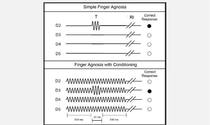
Figure 2.2: Schematics of Finger Agnosia Protocols. The simple finger agnosia assessment (top panel) consisted of a 4AFC protocol where a short test (T) pulse (300 μm, 25 Hz, 40 ms) was delivered to one of the four
digits followed by a subject response interval (RI). The finger agnosia test was also conducted in the presence of conditioning stimuli of amplitudes 30, 40, 50, or 100 μm (bottom panel). The conditioning stimulus was delivered 500 ms prior to, and 500 ms following, the tap of the test digit. For all finger agnosia tasks, subjects indicated which finger was perceived to have received the large amplitude tap by choosing the respective digit on an image
Analysis. For the finger agnosia protocols, accuracy percentages were calculated by
analyzing the ratio of correct to total responses of the subjects. Percent accuracies were trial-independent and reflected accuracies across all 16 trials. The 100 μm conditioning condition was chosen for further analysis because of the significantly lower percent accuracy compared to the simple agnosia task. Percent inaccuracies were quantified for the 100 μm conditioning stimulus by calculating the frequency at which digits were incorrectly chosen. Results were calculated in this manner in order to compare percent inaccuracies with difference limens (DLs), where lower value might suggest higher accuracies and increased discriminative capabilities. The data were analyzed for significance by calculating p-values across mean inaccuracy metrics for each digit. Histograms were plotted in order to visualize the differences among each of the digits with respect to standard error of the means. Statistical t-tests were used to evaluate the difference of the performance of each subject under different conditions. A probability value of less than 0.05 was considered statistically significant.
Auditory Cue Analysis. To ensure that the stimulator did not produce any audible
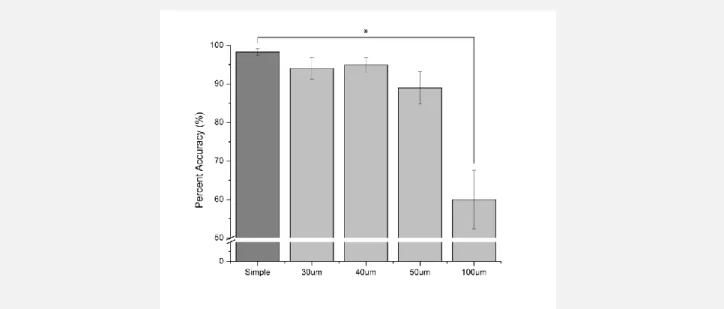
Figure 2.3: Average Percent Accuracy the Effect of Conditioning Stimuli on the Finger Agnosia Task. The average percent accuracy in absence of conditioning stimuli was 98.2±0.9% (n=17). In the presence of 30, 40, 50,
and 100 μm conditioning stimuli, the percent accuracies gradually decreased with increased amplitude of conditioning stimuli: 93.7±3.0% at 30 μm (n=17), 94.9±4.2% at 40 μm (n=16), 89.0±4.2% at 50 μm (n=17,
p<0.06), and 60.0±7.6% at 100 μm(n=5, p<0.01).
Results
(n=17), and accuracy across subjects decreased with increasing amplitude of conditioning stimuli. Conditioning amplitudes of 30 and 40 μm resulted in percent accuracies of
Figure 2.4: Average Percent Inaccuracy on Finger Agnosia with 100 μm Conditioning Stimuli
. Digits D3 and D4 showed the highest percent inaccuracies of 60.0±10.0% and 55.0±14.6%, respectively. There was a statistically significant observation in accurately recognizing and identifying stimulation of D2 at 15.0±10.0%
versus D3 at 30.0±20.0% (p<0.01) and slight discrimination difference between D2 and D4 (p<0.08) in the presence of the 100 μm conditioning stimuli. The other the digit combinations showed no statistical significance in
discrimination capability.
Discussion
The delivery of sinusoidal displacements to a single skin site via mechanical transducer has been used extensively for the study of flutter vibration in both
amplitudes of sufficient size (between 0 and 1000 μm) to activate a broad range of
mechanoreceptors. However, in order to stimulate more than one skin site – either during the course of human psychophysical testing or animal experimentation – it is necessary to position a second vertical displacement stimulator over the second skin site. Our previous device (described in Tannan et al. 2007a) was designed to address this issue by allowing dual site stimulation with automated two-dimensional probe positioning. Although the device reported by Tannan and colleagues was successfully utilized in a number of studies (Tannan et al., 2005b, 2006, 2007b, 2008; Tommerdahl et al., 2007a, 2007b, 2008), it was cumbersome and not ideal for clinical and clinical research venues. The CM-4, described in this report, has the capacity to quickly and easily adjust to fit to most adult, and many juvenile, hand sizes and can deliver vibrotactile stimuli to the tips of four digits. The ability to simultaneously deliver vibrotactile stimuli to a number of digits allows for a great deal of protocol diversity.
In this report, we described a relatively simple four-site finger agnosia protocol to demonstrate the potential utility of the device. The principle finding in the results of this study is that there is an increase in inaccuracies with increases in the amplitude of concurrent conditioning stimulation delivered during the agnosia task, and the ability to perform the task accurately in the presence of that conditioning stimulation is diminished more in digits D3 and D4 than in digits D2 and D5. The decrease in accuracy with increasing amplitudes of synchronized sinusoidal stimulation is consistent with prior reports of
increasing inaccuracies in temporal order judgment (TOJ) in the presence of synchronized and periodic conditioning stimuli. In a study by Tommerdahl and colleagues (Tommerdahl et al., 2007), it was demonstrated that TOJ results obtained from a number of pairs of
conditioning stimulus, the TOJ obtained when the two stimuli were delivered bilaterally was not impacted. This led to the speculation that the impact that the conditioning stimuli – which only had an impact if they were sinusoidal, periodic and synchronous – had on TOJ measures was due to the synchronization of adjacent cortical ensembles in somatosensory cortex, and that the synchronization of these cortical ensembles could have been
responsible for the degradation in temporal order judgment. The conditioning stimuli in this study were also synchronized, periodic and simultaneous, and if the degradation in test performance was due to synchronization of adjacent cortical ensembles similar to what was speculated in the TOJ report, then inaccuracies due to this synchronization would be lower on the digits on the perimeter of the cortical ensemble (i.e., D2 and D5), and the results reflect this prediction. Future studies will consider whether or not subjects with neurological disorders are not impacted by conditioning stimuli, as was found to be the case in
subsequent TOJ studies (e.g., TOJ metrics of subjects with autism were not impacted significantly by conditioning stimuli; Tommerdahl et al., 2008).
The degree of inaccuracies in the different digits with increasing conditioning
stimulation is also consistent with motor studies of digit interdependencies. In studying the autonomy of finger movements, intended motion in one finger often results in simultaneous movement, or enslavement, of other digits. More specifically, D3 and D4 show the most enslavement, or interdependency, of adjacent digits while D2 is characterized by the greatest independence (Häger-Ross and Schieber, 2000). In observing motor-related
cortical potentials (MRCPs), the autonomous nature of D2 was shown to be significantly high while D4 showed the most dependency on other digits (Slobounov et al., 2002). In Figure 4, D2 demonstrates the lowest inaccuracies in the presence of conditioning stimulation while D3 and D4 exhibit the most; thus, in both the motor and sensory based studies, D2 demonstrates the most independence.
neurophysiological mechanisms and sensory percept. The development of new, more versatile devices and methodologies, such as presented in this report, could contribute to bridging decades of neuroscientific research with human perceptual clinical and clinical research studies. One long term goal of our research is to develop sensory based
CHAPTER 3: CM3: A FOUR-POINT PIEZOELECTRIC BASED MRI/MEG COMPATIBLE VIBROTACTILE STIMULATOR1
Overview
Recently, we reported methods for applying multi-site vibratory stimuli to the fingertips. Typically, this involves the use of multiple, individual vibrotactile stimulator and limitations of such an arrangement include difficulty with both positioning the stimuli as well as ensuring that stimuli are delivered in a synchronized and deliberate manner. The device that we reported is a significant improvement on multiple independent stimulators (Holden et al, 2011), and due to both the success of that stimulator and the consequent need to validate a number of findings that had been made with both that device and the precursor of that device (Tannan et al, 2007a), we designed and fabricated a four-site stimulator that could be used in MRI and MEG compatible environments. The device can stimulate four independent skin sites and is primarily designed for stimulating the digit tips. The device is similar to the previously reported device in that it is portable and is ergonomically suited for delivering stimuli to the finger tips, but it has the advantage of being MRI and MEG
compatible. However, the fundamental mechanisms of the device are significantly different from the device that we recently reported since the device is piezo-based rather than VCA based. To demonstrate the reliability of the device for delivering tactile stimulation at four independent sites, a temporal order judgment (TOJ) protocol, in the presence and absence of conditioning stimuli, was conducted on seventeen healthy control subjects. The study produced results that were consistent with prior studies that implicated synchronization of adjacent and near-adjacent cortical ensembles with conditioning stimuli in impacting TOJ _______________________
1A large portion of the work presented in this chapter was completed as a collaborative effort with the following
performance (Tommerdahl et al., 2007). Additionally, the device was used in both an MEG and in MRI pilot studies, and those studies demonstrated that no detectable noise was introduced by the stimulator in those environments.
Introduction
For the past several years, our research group has been working towards the
development of a portable tactile stimulator that could effectively be used to study changes in sensory information processing in clinical and clinical research venues across a diverse spectrum of neurological disorders. Thus far, we have gone through several iterations in the development of this stimulator and the protocols that can be delivered with that stimulator. The current design of the stimulator – as described most recently in Holden et al, 2011 – is optimized for the delivery of vibrotactile stimuli to the finger tips. This optimization was done in order to take advantage of the well-known somatotopic relationships with the concept in mind that delivering stimuli to adjacent digit tips would evoke cortical activity in adjacent and/or near adjacent cortical regions, and that the interactions that result from such stimulus evoked activity will be robustly impacted by alterations in cortical information processing.
The first prototype of the system (Tannan et al., 2005a) was used to demonstrate changes in spatial acuity with repetitive stimulation. A subsequent report described that this change did not occur with individuals with autism, strongly suggesting a lower-than-normal inhibitory response (Tommerdahl et al., 2007a). A second iteration of the device (Tannan et al., 2007a) was much more portable as well as more robust and reliable in its ability to deliver well-controlled vibrotactile stimuli to the skin. The device proved extremely useful, and a number of studies were conducted with it that demonstrated the ability to reliably and reproducibly obtain metrics of neuro-adaptation (Tannan et al., 2007b), temporal order judgment (TOJ) and the impact of synchronized conditioning stimuli on TOJ (Tommerdahl et al., 2007b), the absence of the impact of those same conditioning stimuli on TOJ in
and amplitude discrimination (Zhang et al., 2008), a method for the study of tactile-thermal interactions (Zhang, 2009), a reliable means for measuring amplitude discriminative
capacity and a robust near-linear relationship between duration of repetitive conditioning stimuli and the impact of that conditioning on amplitude discriminative capacity (Tannan et al., 2007b), the below-normal adaptation metrics in autism (Tommerdahl et al., 2007), the impact of NMDA receptor block on adaption metrics (Folger et al., 2009), a demonstration of Weber‘s law (Francisco et al., 2008; Holden et al., 2011) and a robust relationship with neurophysiological data (Francisco et al., 2008), and differences in timing perception in Parkinson‘s Disease (Nelson et al., 2011). More recently, we have developed a newer, more portable and ergonomic model of the device, which is much more suited for a clinical or clinical research environment, and is capable of delivering vibrotactile stimuli to four fingers: the index (D2), middle (D3), ring (D4), and little (D5) fingers (CM4; Holden et al, 2011). The utility of this device has been demonstrated in a report of phenotypic differences within a spectrum of patients with vulvodynia (Zhang et al., 2011a), in a report that
described stability of cortical plasticity across a wide age spectrum (Zhange et al, 2011b), and in a paper that describes its utility for describing phenotypic differences within the autism spectrum via modulating vibrotactile stimuli (i.e., sinusoidal stimuli that dynamically change in amplitude; Francisco et al, 2011).
Due, in part, to the fact that we have experienced a great deal of success in demonstrating phenotypic differences between and within a number of neurological alterations, we determined that it would be useful to design and fabricate a
Magnet compatible stimulators are typically designed to use pneumatic or piezo-ceramic parts. Each has its own advantages and disadvantages. Pneumatic devices for use in magnetic environments are typically built with plastic and latex tubing, with the
controlling electronics kept away from the magnets. These devices typically have a low frequency range with a maximum near 100Hz and require pressurized air to operate
properly (Briggs et al, 2004;) Golaszewski et al (2002) was able to avoid using compressed air canisters by using a BP cuff and their use of a DC motor and pneumatic by-pass line gave a wider range (1-150Hz) and larger amplitude (up to 2mm) than most devices. The device designed by Briggs et al had the potential to support multiple probe tips, each with a different frequency, amplitude, and pattern, though the prior calculations were necessary to lower the risk of bursting the latex diaphragm. The one major disadvantage of any
Methods
Hardware. The cortical metrics (cm-3; see figure 1) stimulator was developed in our
Figure 3.1: Four Site Vibrotactile Stimulator. Each of the four probe tips is positioned by rotating the four independently-positioned drums to maximize contact between finger pads and the stimulator tips. During an experimental session, subjects were seated comfortably in a chair with their arm resting on the arm rest attached
to the head unit of the device. Digits D2 through D5 were then positioned for vibrotactile stimulation.
which serves to mechanically isolate the test subject from the internal piezo driver voltages. The amount of protrusion for each probe is independently adjustable as are the positions of the holes to accommodate the length of the subject‘s fingers as he/she wraps their hand around the stimulator head unit. The piezo bender motion is converted into linear
displacement by the four-bar compliant mechanism to drive the cylindrical plastic stimulator probe tips linearly into and out of each 130mm diameter disk in the stimulator head unit, according to prescribed sinusoidal waveforms. The moving components of the stimulator tips are directly manufactured from ABS ―plus‖ material by 3-D FDM as a single compliant mechanism component integrating a mounting flange, a thin-beam four-bar linkage, coupling lugs for attaching one piezo bender into each actuator mechanism, and the extension to the mechanical stimulator tip. The compliant four-bar linkage mechanism allows the stimulator tip to be displaced vertically along a straight line for a distance of ± 1 mm. The 4-bar compliant mechanism also provides a very low hysteresis linear restoring force to center each tip vertically when no voltage is applied to the piezo benders. The entire four-bar mechanism is 5.3 mm in thickness, and is positioned such that the stimulator tips move along a radial line extending from the center of each 130mm disk, perpendicular to the outer circumference of each disk. The resulting linearized piezo bender mechanisms generate extremely linear force outputs as a function of drive voltage with very low hysteresis due to the ―frictionless‖ nature of the single piece bearing-less four bar compliant mechanism. The position of the vibrating tips is not sensed for the CM3 units, unlike the optical position sensors in the previously reported CM4 systems (Holden et al, 2011). Care was taken throughout the design of the CM3 stimulator head to exclude magnetic and/or electrically conductive components that might interfere with or be damaged by the presence of strong external magnetic fields associated with modern magnet-based imaging systems.
CAD files, also by ExpressPCB. The hybrid circuit is interfaced via four parallel pin
connectors (2 banks of 50 pins for digital signals and 2 banks of 34 pins for analog signals) to an internal NI-USB-6259 data acquisition (DAQ) board. The DAQ board then interfaces via a USB connection to any standard PC running Microsoft Windows XP or later.
Software. A custom line-of-business application was developed for the Microsoft .Net
platform using the C# programming language and Windows Presentation Foundation (WPF) framework to control the stimulator and administer the data collection protocols. The interface was designed to be intuitive, extensible, and aesthetically pleasing. The software needed to be extensible to facilitate the development of future protocols for a device as flexible as the CM-3. The core extensibility was achieved by using a ―plugin‖ architecture with a shell application whose function is to discover, load and execute small plugins. The shell exposes a software contract (an inheritable C# class) that is consumed and extended by each plugin. Each task described in this paper represents one such plugin. Most
traditional neuropsychological protocols using the standard X-alternative forced-choice (X-AFC) tracking method (Cornsweet, 1962) can be created with only a couple of dozen lines of C# code. While most plugins interact directly with the CM-3 stimulator, this is not a
requirement of the plugin contract. Plugins can, for example, be designed to collect arbitrary subject information pertinent to the given study (e.g. participant demographics, relevant medical history, various surveys, etc.). The net effect is not only a significant reduction in the amount of clinical paperwork that needs to be completed by each participant, but also a marked reduction in data-entry time for clinicians. All data collected by the application are stored in an encrypted (128-bit RC4) SQLite database in a user-specified location. Each database can be shared with multiple instances of the shell application, providing a
mechanism for seamless networking of CM-3 stations (Holden, et al, 2011). The software is also capable of storing, as well as creating and customizing, all relevant initialization
batteries allow for greater reuse of each plugin, resulting in shorter development times a more efficient workflow throughout an experiment.
Protocols. In order to demonstrate exemplary use of the CM-3, 3 studies were
conducted. First, Temporal Order Judgment (TOJ), in the presence and absence of
conditioning stimuli, was collected and compared with data previously reported with a VCA based stimulator (Tommerdahl et al, 2007b). Second, pilot studies with fMRI were
conducted in order to ascertain compatibility of the stimulator in an MRI environment. Third, pilot studies in an MEG environment were conducted in order to determine whether or not the CM3 introduced noise in that environment. Additionally, both MEG and MRI studies compared the responses evoked by stimulating different finger tips.
Subjects. Thirty healthy subjects ranging from 22 to 26 years of age, were recruited
for the TOJ study. None of the subjects reported any neuropsychological impairment and all were naïve to both the study design and issue under investigation. The study was
performed in accordance with the Declaration of Helsinki, all subjects gave their informed consent, and the experimental procedures were reviewed and approved in advance by an institutional review board.
Experimental Procedure – TOJ with and without background noise. During an
natural hand shape of each subject. After proper positioning, if the probe tips still failed to make proper contact with the digits, the tips themselves were either raised or lowered. Once adjusted, the probe tips were locked in place prior to initiation of the battery so that they would remain immobile during testing. At the start of each run, the four tips were driven towards the tips of the fingers in order to ensure good contact with the skin.
During the assessment, the device delivered sinusoidal skin displacements
(vibrations) via flat Delrin probes (5-10 mm in diameter) positioned to make contact with the tips of the index (D2), middle (D3), ring (D4), and little (D5) fingers of the right hand. The independent probe tips were computer-controlled and capable of delivering a wide range of vibrotactile stimuli of varying frequencies (Hz) and amplitudes (μm). Stimulus parameters were specified by test algorithms that were based on specific protocols as well as subject responses during those protocols.
Subjects viewed a computer monitor that provided continuous visual cueing during the experimental session. Specifically, an onscreen light panel indicated to the participant when stimuli were being delivered and when subjects were to respond. Training trials were included prior to testing, and the subjects were given performance feedback only prior to trials during data acquisition. The sensory testing session was conducted by application of low frequency (25 Hz) vibration to selected fingers. Each battery of testing lasted between 15 and 20 minutes depending on the protocols being run and on subject performance. Each individual protocol typically lasted 2 to 3 minutes.
Temporal Order Judgement, without (TOJs) and with carrier (TOJc) stimulus. All
was decreased for correct answers and increased for incorrect answers). In one condition, there was no concurrent stimulation (TOJs) and in the second condition (TOJc), a 25 Hz concurrent carrier (20 µm) stimulus was delivered throughout each 1 s trial-interval. The tasks were performed for six digit combinations on each subject: D2-D2, D2-D4, D2-D5, D3-D4, D3-D5 and D4-D6. Noise introduction in the MRI environment
The amount of noise introduced into the MRI environment by the CM3 was measured by collecting MRI data, in the absence of a human subject, with the CM3 in four different locations or situations: 1) The CM3 was not in in the scan room; 2) the CM3 was placed on the scanner table but not connected to either power or computer; 3) the CM3 was placed on the scanner table and connected to the driving hardware in the control room, without the power turned on; and 4) the CM3 was connected to both computer and power, was turned on and the stimulators were turned on.
The stability scans were acquired on a 3T GE Signa LX MR scanner (Waukesha, WI). A GE structural phantom was scanned using a reverse spiral acquisition
(TR/TE/FA=1000/27.5/60, 200 cm FOV, 13 slices, 5/1 thickness/gap, 64x64 matrix, 180 frames collected).
Using a region of interest, temporal and spatial signal-to-noise ratio (SNR), the temporal drift and normalized frequency magnitude were calculated. In addition, the summed absolute temporal difference of the time course was calculated and plotted, as a measure of frame-to-frame stability. Comparisons were made between the scans obtained in the four different conditions.
Results
stimulation, is reduced. Additionally, DLs for the TOJ task with synchronized conditioning stimuli were not significantly elevated when the task was performed across D2-D5. In other words, when cortical distance was greatest between the stimulus sites, the impact of the conditioning stimulus was smallest.
Studies were also conducted in the presence and absence of MEG and MRI environments in order to ascertain whether or not the device introduced noise and was magnet compatible. There was no detectable noise evoked by the CM3 stimulator in either of these environments.
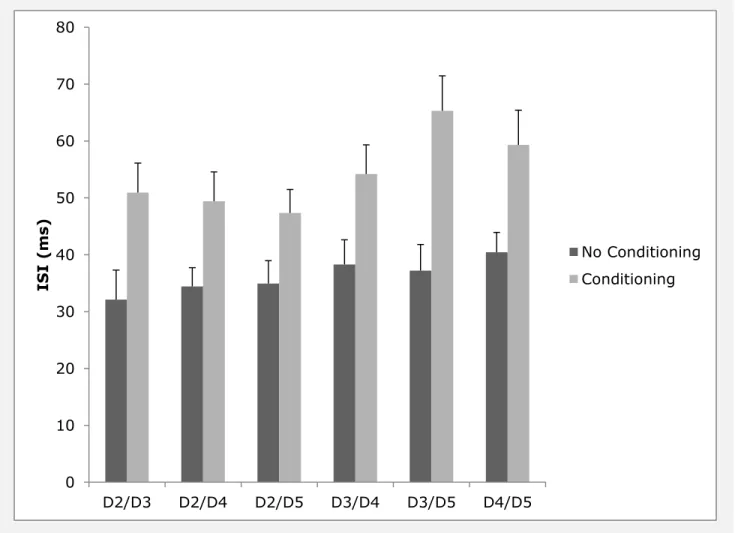
The TOJ task was evaluated in order to quantify the ability of subjects to recognize and identify stimulated digits in the absence and in the presence of conditioning stimuli.
Figure 3.2: Impact of Conditioning Stimulus on TOJ Performance
0 10 20 30 40 50 60 70 80
D2/D3 D2/D4 D2/D5 D3/D4 D3/D5 D4/D5
ISI
(ms) No Conditioning
MRI recording results. There were no significant differences observed in any of the
recordings that were obtained during scans in the four different conditions of CM3
placement and operation. No dominant noise spikes were observed in either the frequency spectrum or difference time course, and with steady temporal and spatial SNR in each case (1 – no CM3 present, 2- CM3 present, 3 – CM3 plugged in and 4- CM3 operating): 1) 117:180, 2) 148:190, 3) 135:177, 4) 140:178. Thus, the device induced no detectable MR artifacts.
Discussion
The delivery of sinusoidal displacements to a single skin site via mechanical transducer has been used extensively for the study of flutter vibration in both
psychophysical and neurophysiological settings for a number of decades. Exemplary uses of such a device are described in Goble and Hollins, 1993; Juliano et al., 1989; LaMotte and Mountcastle, 1975; Mountcastle et a., 1969; Tannan et al., 2006; Tommerdahl et al., 1993, 1998, 2002; and Vierck and Jones, 1970. Typically, stimuli that can be delivered through mechanical transducers – vertical displacement stimulators such as the one originally described by Chubbuck (1966) – were used for studies of somatosensation and are very well equipped to deliver sinusoidal stimuli at a frequency range (1 to 250 Hz) with amplitudes of sufficient size (between 0 and 1000 μm) to activate a broad range of
many juvenile, hand sizes and can deliver vibrotactile stimuli to the tips of four digits. The ability to simultaneously deliver vibrotactile stimuli to a number of digits allows for a great deal of protocol diversity. The ability to deliver these stimuli in an MRI and MEG
environments expands the functionality of the stimulator. Not only can behavioral tests be performed, but neurophysiological correlates can be obtained as well.
In this report, we described the use of a relatively simple protocol – Temporal Order Judgment (TOJ) in the presence and absence of conditioning stimuli. This protocol has been previously described (Tommerdahl et al, 2007x, 2008x), and in those studies, stimulation was provided to D2 and D3 in order to observe the impact that synchronized and periodic stimuli had on TOJ performance. Performance on the TOJ task itself was relatively robust across the digit combinations, although performance with D4-D5 appears to be worse than other digit combinations, and this would be expected due to partial overlap between D4-D5 representations. Post-conditioning, there were significant differences with the task using different digit combinations. As the separation between the test sites located between D2 and the other digits increased (D2 was paired with D3, D4 and D5 on separate tests), there was a decrease in the impact of the conditioning stimulus. Specifically, there was little impact of conditioning on the D2-D5 pair although there was impact on performance when D2 was paired with D3 or D4. The interpretation of this finding is that there is a critical distance between cortical representations that needs to occur before the conditioning stimulus no longer has an effect. In the case of the D4-D5 pairing, the cortical distance is already minimized and thus, the conditioning stimulus that normally impacts TOJ
performance with D2-D3 pairing by functionally linking those cortical representations, has effectively already linked the D4-D5 sites.
The principle finding in the results of this study is that there is an increase in
with synchronized sinusoidal stimulation is consistent with prior reports of increasing
inaccuracies in temporal order judgment (TOJ) in the presence of synchronized and periodic conditioning stimuli. In a study by Tommerdahl and colleagues (Tommerdahl et al., 2007), it was demonstrated that TOJ results obtained from a number of pairs of stimulus sites – unilateral as well as bilateral – were comparable. However, in the presence of a 25Hz
conditioning sinusoidal stimulus which was delivered both before, concurrently and after the TOJ task, there was a significant increase in the TOJ measured when the two stimuli were located unilaterally on digits D2 and D3. In the presence of the same 25Hz conditioning stimulus, the TOJ obtained when the two stimuli were delivered bilaterally was not
impacted. This led to the speculation that the impact that the conditioning stimuli – which only had an impact if they were sinusoidal, periodic and synchronous – had on TOJ
measures was due to the synchronization of adjacent cortical ensembles in somatosensory cortex, and that the synchronization of these cortical ensembles could have been
responsible for the degradation in temporal order judgment. The conditioning stimuli in this study were also synchronized, periodic and simultaneous, and if the degradation in test performance was due to synchronization of adjacent cortical ensembles similar to what was speculated in the TOJ report, then inaccuracies due to this synchronization would be lower on the digits on the perimeter of the cortical ensemble (i.e., D2 and D5), and the results reflect this prediction. Future studies will consider whether or not subjects with neurological disorders are not impacted by conditioning stimuli, as was found to be the case in
subsequent TOJ studies (e.g., TOJ metrics of subjects with autism were not impacted significantly by conditioning stimuli; Tommerdahl et al., 2008).
The role of neural communication between adjacent and non-adjacent cortical regions plays an important role in understanding the relationship between
research studies. One long term goal of our research is to develop sensory based
CHAPTER 4: VIBROTACTILE STIMULATOR SOFTWARE INTERFACE
Both the CM3 and CM4 vibrotactile stimulators were designed to leverage identical data acquisition (DAQ) circuitry produced by National Instruments. Each DAQ board is accompanied by a software license to a set of application development software libraries developed by National Instruments for creating end-user applications that interface with their DAQ hardware. The availability of application development tools from the hardware vendor was a primary driving force in selecting the data acquisition board. Versions of the application development libraries exist for several different programming languages and operating systems, but the CM3 and CM4 devices only utilize the versions for Microsoft‘s .NET Framework and National Instruments‘ own LabVIEW integrated development environment (IDE). A series of software applications had to be created to calibrate and control the delivery of the aforementioned vibrotactile stimuli.
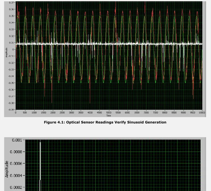
Figure 4.1: Optical Sensor Readings Verify Sinusoid Generation
Figure 4.2: FFT of Measured Sinusoid in Figure 1
range. Nine desired amplitudes were chosen in the range of 50 to 700 microns. A sinusoid lasting one second representing the un-calibrated command signal calculated for each amplitude was administered and the position was recorded from the optical sensor at a sample rate of 10kHz. The peak-to-peak amplitudes of the recorded optical waveforms were calculated at 200ms intervals and averaged together as a measure of the average peak-to-peak amplitude for the entire sinusoid. The difference of the commanded and measured amplitude was calculated for each sinusoid and a simple linear regression
equation was then calculated for each frequency. The procedure was then replicated using the calibrated command signal to verify that the measured and commanded amplitudes now matched. The figures below show an example output from this calibration program and demonstrate its effectiveness.
Figure 4.4: VCA Calibration Application - Output from a completed calibration exercise. The coefficients of determination for the VCAs are all > 0.999. The measured amplitudes are graphed for command amplitudes
ranging from 200 microns to 600 microns across frequencies from 10 to 50hz.
user interface. In order for this system to be successful at a clinical level, the interface would have to be intuitive and aesthetically pleasing enough for an experimenter without intimate knowledge of the entire system to navigate. These requirements would ultimately result in a shift from the laboratory-centric LabVIEW programming language to the more widespread C#.
C# is an object-oriented programming language (OOP) built on Microsoft‘s .NET Framework. Its syntax is similar to both of its predecessors, Java and C++. Like Java, C# applications are not compiled directly into machine language, but to an intermediate
language (Microsoft Intermediate Language (MSIL)) that gets executed in a virtual runtime environment. This gives developers lots of conveniences not afforded by other languages like C/C++. For example, memory management in both C# and Java is handled by the runtime unless explicitly overridden by the developer leading to fewer software memory leaks and thus greater application stability. With all of the similarities between Java and C#, choosing between the two came down to their ability to create modern graphical user interfaces (GUIs).
In 2006, Microsoft released the Windows Presentation Framework (WPF), a
framework for facilitating the creation rich user interfaces. It introduced a markup language called the Extensible Application Markup Language (XAML), based on the Extensible Markup Language (XML), which separates the ‗view‘ logic used to control a user interface from the underlying ‗model‘ logic. This concept is not new in software development, and it is
interface. By leveraging this data binding capability, WPF was also able to provide a flexible animation framework that significantly reduced the amount of development time required to create aesthetically pleasing transitions within the GUI. Those key features ultimately led to the selection of C# as the language of choice for developing the first clinical GUI for our behavioral protocols. It should be noted that the only majorly obvious flaw of C# (and WPF) was that it was limited to running on the Windows® operating system. However, this was not a significant concern since the hardware drivers for the DAQ board also shared this limitation.
Device Driver Library
After choosing C#, the first iteration of the application was divided into three
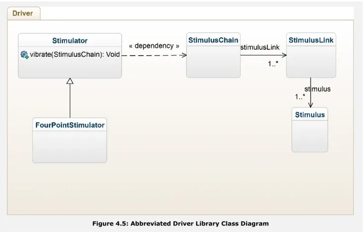
Figure 4.5: Abbreviated Driver Library Class Diagram
The main Stimulator class served to encapsulate all of the functionality available to the upper layers. It is important to note that the Stimulator classes utilizes the Factory pattern (Gamma et al 1994) and does not expose a public constructor function. This prevents the upper software layers from attempting to create an instance of a Stimulator object when there is no physical hardware connected to the computer, and allows the Stimulator class to manage multiple devices plugged in to the same machine
which is significantly more intuitive when developing behavioral protocols. Complex sinusoidal vibrations are pieced together by using a chain of simple sinusoids. The most basic Stimulus class represents a single sinusoidal waveform with a given amplitude, frequency, and duration. An instance of the StimulusLink class represents a single base Stimulus with an optional second Stimulus that will be superimposed. The duration of the superimposed stimulus is ignored, as it must be the same as the base sinusoid. One or more StimulusLinks can be sequenced to form a StimulusChain. The StimulusChain class includes helper functions to pad a chain to a given duration or to introduce delays without having to manually create 0 amplitude sinusoids. A set of StimulusChain objects is passed to the ‗vibrate‘ method of a Stimulator instance to where each chain is converted to the appropriately calibrated driving voltages for a given DAQ hardware channel and ultimately passed to the stimulator via the USB connection. It should be noted that the upper software layers can subscribe to a software event that will be fired just before the USB transfer begins to enable synchronization with user interface elements to which this low layer is completely naïve. This library is used in every software application that controls a CM3 or CM4 stimulator, regardless of the GUI.
Common Plugin Library
The next software layer was also a software library that cannot be executed as a standalone application. The broad scope of possible behavioral protocols that could be realized using a portable vibrotactile stimulator made it clear that our lab could not possibly perform all of the research tasks alone. In order to facilitate collaboration with other
Figure 4.6: Abbreviated Class Diagram of Common Plugin Interface Library
The plugin architecture is centered around the implementation of a single base Protocol class. Implementation of this class is the bare minimum required to be recognized by the top software layer. In a nutshell, the Protocol class merely provides a small set of virtual public functions to initialize, start, stop and pause the Protocol that can be called from the top layer. The initialization function depends on the Subject class, which encapsulates the necessary demographic data to represent the person on whom the
The simplest provided implementation of a Protocol is the derived class, Survey. The Survey class represents a Protocol that can be executed without a stimulator. Many
clinicians had legacy demographical surveys that were administered on paper during each clinical visit by a particular subject, so the Survey class provided a simple way to collect that data electronically. An example of one such implementation of the Survey class is an
electronic version of the Autism Quotient survey (Baron-Cohen et al 2001).
The other major subclass of the Protocol class is the StandardProtocol class. Classes that inherit from the StandardProtocol class require the presence of a CM stimulator and have a common execution flow directed by an overridden ‗start‘ function of the Protocol class. All behavioral protocols that have been designed so far execute a sequence of trials with various methods of transitioning from one trial to the next. Instances of the
StandardProtocols do this through the implementation of the ParallelStaircase class. A bottom-up approach is best to understand how this works.
At the lowest level, the Staircase class represents a simple list of trials and
associated metadata. This metadata includes all of the information needed to execute and record data from a particular trial e.g. stimulus amplitude, user response, inter-stimulus interval etc. The Staircase class also contains an instance of a TrackingBehavior that describes the orderly transition from one trial to the next. An example of a
TrackingBehavior is an implementation of a modified von Békésy tracking algorithm
first trial in that dependence hierarchy, and thus is the logical place for an instance of the DataOutput class.
The DataOutput class is responsible for recording the aforementioned starting
parameters as well as the raw data collected during execution of its parent LinearStaircase. After the last trial in a LinearStaircase is completed (according to the TrackingBehavior), the ‗save‘ method of the DataOutput class is called to store the data to the computer‘s hard disk. The data can be stored either to a pair of plain-text files or an encrypted SQLite database depending on the security requirements of the environment in which the data was collected.
Finally, the ParallelStaircase class can encompass one or more instances of the LinearStaircase class that are executed simultaneously. Since data saving is controlled independently in each LinearStaircase, multiple sets of data can be generated for a single StandardProtocol if it happens to contain multiple LinearStaircases. The primary use for the ParallelStaircase class is during protocols that leverage tactile illusions that could also be a cue to the subject who understands the task. For example, a conditioning vibration that is always delivered at the same site as the ‗test‘ stimulus of a 2AFC protocol could be
considered a cue to the correct answer. In order to remove this confound, a second LinearStaircase with the conditioning vibration at the opposite site can be executed simultaneously with trials from each LinearStaircase randomly interleaved together.
The plugin library also exposes a few helper classes in order to facilitate the creation of custom rich user interfaces. Examples of such are the Feedback and DigitSelector
task. In one such instance, a series of images similar to a short comic are presented after the completion of each trial, but they are unrelated to the correctness of the preceding response. The Feedback class is able to deliver all three types of feedback while remaining protocol agnostic and thus reusable across multiple behavioral tasks.
Shell Application
Figure 4.8: Abbreviated Class Diagram of Shell Application
The top software layer is the ‗shell‘ layer. Its primary job is to locate, load, and execute plugins built using the common plugin library. In order to do this, it needs to provide two things to the plugins it executes: an instance of the Stimulator class and an instance of the Subject class. Therefore, it is also responsible for enumerating the attached stimulators and collecting the required information from the user to create a Subject. The shell also includes an interface to create batteries (XML representations of Protocol classes, appendix 4.3) of behavioral protocols with customized starting parameters that are
behavioral task and modifying the appropriate starting parameters on-the-fly. Finally, the shell provides mechanisms for securely uploading collected behavioral data to a centralized database (where it will eventually be analyzed) as well as for automatically updating plugins for remote installations of the software package.
Database
Currently, there are ongoing academic and clinical collaborations in six countries worldwide, who have collectively performed tens of thousands of experimental runs on roughly 3000 participants. As this data began to accrue, storing it in an efficient and easily accessible format became a top priority. Most of the research data had previously been stored and analyzed using traditional tools like Microsoft Excel®. Excel was perfect for analyzing small datasets with an isolated set of conditions, but woefully inadequate for querying and analyzing the amount of data that is currently being collected. A relational database management system (RDBMS) (Codd et al 1970) was selected as the solution to this growing problem.