HP ProLiant ML350 Gen9 Server
User Guide
Abstract
This document is for the person who installs, administers, and troubleshoots servers and storage systems. HP assumes you are qualified in the servicing of computer equipment and trained in recognizing hazards in products with hazardous energy levels.
© Copyright 2014 Hewlett-Packard Development Company, L.P.
The information contained herein is subject to change without notice. The only warranties for HP products and services are set forth in the express warranty statements accompanying such products and services. Nothing herein should be construed as constituting an additional warranty. HP shall not be liable for technical or editorial errors or omissions contained herein.
Linux® is the registered trademark of Linus Torvalds in the U.S. and other countries.
Microsoft® and Windows® are U.S. registered trademarks of Microsoft Corporation.
microSD is a trademark or a registered trademark of SD-3C in the United States, other countries or both. Red Hat® is a registered trademark of Red Hat, Inc. in the United States and other countries.
Contents
Component identification ... 7
Front panel components ... 7
Front panel LEDs and buttons ... 10
Rear panel components ... 11
Rear panel LEDs ... 12
System board components ... 13
System maintenanace switch ... 14
NMI functionality ... 15
DIMM slots ... 15
Using the System Insight Display ... 16
System Insight Display LEDs ... 17
System Insight Display LED combinations ... 18
Device numbering ... 19
Hot-plug drive LED definitions ... 20
Hot-plug fans ... 21
Operations... 23
Power up the server ... 23
Power down the server ... 23
Remove the security bezel ... 24
Remove the tower bezel ... 24
Remove the access panel ... 24
Install the access panel ... 25
Extend the server from the rack ... 26
Remove the air baffle ... 27
Install the air baffle ... 28
Remove a fan ... 29
Remove the fan cage ... 29
Remove the optical drive ... 30
Remove a component drive cage blank ... 31
Setup ... 33
Optional installation services ... 33
Optimum environment... 33
Space and airflow requirements ... 33
Temperature requirements ... 34
Power requirements ... 35
Electrical grounding requirements ... 35
Server warnings and cautions ... 35
Identifying server shipping carton contents ... 36
Installing hardware options ... 36
Setting up a tower server ... 37
Installing the server into a rack ... 37
Rack warnings ... 42
Installing the operating system ... 43
Powering on and selecting boot options in UEFI Boot Mode ... 44
Hardware options installation ... 45
Introduction ... 45
Second processor option ... 45
Memory options ... 50
HP SmartMemory ... 50
Memory subsystem architecture ... 51
Single-, dual-, and quad-rank DIMMs ... 51
Population order ... 52
DIMM identification ... 52
Installing a DIMM ... 52
Install the security bezel ... 54
Install the optical drive ... 54
Tower to Rack conversion ... 56
System Insight Display Option ... 60
SFF media cage option ... 63
LFF media cage option ... 68
HP Smart Array controller Mini-SAS Y-cable option ... 72
Drive options ... 76
Removing a drive blank ... 76
Installing a hot-plug drive ... 77
Removing a drive ... 78
Graphic card option ... 79
Storage controller options ... 83
Installing the HP Flexible Smart Array Controller option ... 84
HP Smart Array Controller option ... 86
HP Smart Storage Battery ... 87
Installing a hot-plug redundant fan ... 88
Eight-bay SFF drive cage option... 91
Eight-bay LFF drive backplane option ... 94
HP Trusted Platform Module option ... 96
Installing the Trusted Platform Module and security rivet ... 96
Retaining the recovery key/password ... 97
Enabling the Trusted Platform Module ... 98
Cabling ... 99
Media device data cabling ... 99
Optical device cabling ... 100
HP Flexible Smart Array Controller Mini-SAS cabling ... 101
HP Smart Array Controller Mini-SAS Y-cabling ... 101
Software and configuration utilities ... 104
Server mode ... 104
Product QuickSpecs ... 104
HP iLO ... 104
Active Health System ... 105
HP RESTful API support for HP iLO ... 106
Integrated Management Log ... 106
HP Insight Remote Support ... 107
Intelligent Provisioning ... 107
HP Insight Diagnostics ... 108
Erase Utility ... 108
Scripting Toolkit for Windows and Linux ... 109
HP Service Pack for ProLiant ... 109
HP UEFI System Utilities... 110
Using HP UEFI System Utilities ... 110
Flexible boot control ... 110
Restoring and customizing configuration settings ... 111
Secure Boot configuration ... 111
Embedded UEFI shell ... 112
Embedded UEFI diagnostics ... 112
HP RESTful API support for UEFI ... 112
Re-entering the server serial number and product ID ... 112
Utilities and features ... 113
HP Smart Storage Administrator ... 113
ROMPaq utility ... 113
Automatic Server Recovery ... 113
USB support ... 113
USB support ... 114
Redundant ROM support ... 114
Keeping the system current ... 115
Drivers ... 115
Software and firmware ... 115
Version control ... 115
HP operating systems and virtualization software support for ProLiant servers ... 116
HP Technology Service Portfolio ... 116
Change control and proactive notification ... 116
Troubleshooting ... 117
Troubleshooting resources ... 117
Battery replacement ... 118
Regulatory information ... 120
Safety and regulatory compliance ... 120
Belarus Kazakhstan Russia marking ... 120
Turkey RoHS material content declaration ... 121
Ukraine RoHS material content declaration ... 121
Warranty information ... 121
Electrostatic discharge ... 122
Preventing electrostatic discharge ... 122
Grounding methods to prevent electrostatic discharge ... 122
Specifications ... 123
Environmental specifications ... 123
Server specifications ... 123
Power supply specifications ... 124
HP 500W Flex Slot Platinum Hot Plug Power Supply ... 124
HP 800W Flex Slot Platinum Hot Plug Power Supply ... 125
Support and other resources ... 126
Before you contact HP ... 126
HP contact information ... 126
Customer Self Repair ... 126
Acronyms and abbreviations ... 134
Documentation feedback ... 138
Component identification
Front panel components
•
SFF model (Tower orientation)Item Description
1 SFF SAS/SATA drives
2 Serial number/iLO information pull tab1 3 Drive cage bay
4 Optical drive bay 5 Media/drive cage bays 6 USB 2.0 connectors (2)
•
SFF model (Rack orientation)Item Description
1 SFF SAS/SATA drives
2 Serial number/iLO information pull tab1 3 Drive cage bay
4 Optical drive bay 5 Media/drive cage bays 6 System Insight Display bay 7 USB 2.0 connectors (2)
1The serial number/iLO information pull tab is double-sided. The top side shows the server serial number, and the reverse side shows the default iLO account information. The same information is printed on a label attached to the chassis.
Item Description
1 Media/drive cage bay
2 Drive cage bay
3 Serial number/iLO information pull tab1
4 LFF SAS/SATA drives
5 Optical drive bay
6 USB 2.0 connectors (2)
•
LFF model (Rack orientation)Item Description
1 Media/drive cage bay
2 Drive cage bay
3 Serial number/iLO information pull tab1
4 LFF SAS/SATA drives
5 Optical drive bay
6 USB 2.0 connectors (2)
7 System Insight Display bay
1The serial number/iLO information pull tab is double-sided. The top side shows the server serial number, and the reverse side shows the default iLO account information. The same information is printed on a label attached to the chassis. For more information on box and drive numbering, refer to Device numbering (on page 19).
Front panel LEDs and buttons
Item Description Status
1 UID button/LED Solid blue = Activated Flashing blue:
• 1 Hz/cycle per sec = Remote management or firmware upgrade in progress
• 4 Hz/cycle per sec = iLO manual reboot sequence initiated
• 8 Hz/cycle per sec = iLO manual reboot sequence in progress
Off = Deactivated
2 Health LED Solid green = Normal
Flashing green (1 Hz/cycle per sec) = iLO is rebooting
Flashing amber = System degraded1
Flashing red (1 Hz/cycle per sec) = System critical1 3 NIC status LED Solid green = Link to network
Flashing green (1 Hz/cycle per sec) = Network active Off = No network activity
4 Power On/Standby button and
system power LED Solid green = System on Flashing green (1 Hz/cycle per sec) = Performing power on sequence
Solid amber = System in standby Off = No power present2
1To identify components in a degraded or critical state, see the Systems Insight Display LEDs, check iLO/BIOS logs, and reference the server troubleshooting guide.
2Facility power is not present, power cord is not attached, no power supplies are installed, power supply failure has occurred, or the power button cable is disconnected.
Rear panel components
Item Description
1 Slot 1 PCIe3 x16 (8, 4, 1) (for Processor 1) 2 Slot 2 PCIe3 x8 (4, 1) (for Processor 1) 3 Slot 3 PCIe3 x16 (16, 8, 4, 1) (for Processor 1) 4 Slot 4 PCIe3 x8 (4, 1) (for Processor 1) 5 NIC connector 2
6 NIC connector 4 7 Serial connector
8 Slot 5 PCIe2 x8 (4, 1) (for Processor 2) 9 Slot 6 PCIe3 x16 (16, 8, 4, 1) (for Processor 2) 10 Slot 7 PCIe3 x8 (4, 1) (for Processor 2) 11 Slot 8 PCIe3 x16 (16, 8, 4, 1) (for Processor 2) 12 Slot 9 PCIe3 x8 (4, 1) (for Processor 2) 13 Power supply 4 14 Video connector 15 Power supply 3 16 iLO connector 17 NIC connector 3 18 NIC connector 1 19 Power supply 2 20 USB 2.0 connectors (2) 21 USB 3.0 connectors (2) 22 Power supply 1
Rear panel LEDs
Item Description Status
1 NIC activity LED Green or flashing green = Network activity Off = No network activity
2 NIC link LED Green = Linked to network Off = No network connection 3 Power supply LED (4) Green = Normal
Off = One or more of the following conditions exists:
• Power is unavailable.
• Power supply failed.
• Power supply is in standby mode.
• Power supply exceeded current limit. 4 iLO link LED Green = Linked to network
Off = No network connection
5 iLO activity LED Green or flashing green = Network activity Off = No network activity
6 UID LED Solid blue = Activated
Flashing blue:
• 1 Hz/cycle per sec = Remote management or firmware upgrade in progress
• 4 Hz/cycle per sec = iLO manual reboot sequence initiated
• 8 Hz/cycle per sec = iLO manual reboot sequence in progress Off = Deactivated
System board components
Item Description
1 slot9 PCIe3 x8 (4,1) (for Processor 2) 2 slot8 PCIe3 x16 (16,8,4,1) (for Processor 2) 3 slot7 PCIe3 x8 (4,1) (for Processor 2) 4 slot6 PCIe3 x16 (16,8,4,1) (for Processor 2) 5 slot5 PCIe2 x8 (4,1) (for Processor 2) 6 DIMM slots for Processor 1
7 Processor 1
8 slot4 PCIe3 x8 (4,1) (for Processor 1) 9 slot3 PCIe3 x16 (16,8,4,1) (for Processor 1) 10 slot2 PCIe3 x8 (4,1) (for Processor 1) 11 Slot1 PCIe3 x16 (8,4,1) (for Processor 1) 12 HP Smart Storage Battery connector
13 SATA port 4
14 SATA port 5
15 Internal USB 3.0 connector
16 x4 SATA port 2
17 x4 SATA port 1
18 Internal USB 2.0 connector
19 Flexible Smart Array Controller connector 20 Internal USB tape drive connector
Item Description
22 DIMM slots for Processor 2
23 HP System Insight Display connector 24 External thermal cable connector
25 Front IO connector
26 24-pin power supply connector
27 Processor 2
28 RPS connector
29 8-pin power supply connector
30 Fans connector
31 HP Smart Storage Battery connector
32 System battery
33 Discovery service connector 34 System maintenance switch
35 NMI header
36 TPM connector
37 HP Smart Storage Battery connector
System maintenanace switch
Position Default Function
S1 Off Off = iLO security is enabled. On = iLO security is disabled. S2 Off Off = System configuration can be
changed.
On = System configuration is locked. S5 Off Off = Power-on password is enabled. On = Power-on password is disabled.
S6 Off Off = Normal.
On = ROM reads system configuration as invalid.
S7 Off Off = Set default boot mode to UEFI. On = Set default boot mode to legacy. S10 Off Off = Tower configuration.
On = Rack configuration. S3, S4, S8,
S9, S11, S12
— Reserved
To access the redundant ROM, set S1, S5, and S6 to on.
When the system maintenance switch position 6 is set to the On position, the system is prepared to erase all system configuration settings from both CMOS and NVRAM.
CAUTION: Clearing CMOS and/or NVRAM deletes configuration information. Be sure to properly configure the server or data loss could occur.
IMPORTANT: Before using the S7 switch to change to Legacy BIOS Boot Mode, be sure the HP Dynamic Smart Array B140i Controller is disabled. Do not use the B140i controller when the server is in Legacy BIOS Boot Mode.
NMI functionality
An NMI crash dump creates a crash dump log before resetting a system which is not responding.
Crash dump log analysis is an essential part of diagnosing reliability problems, such as failures of operating systems, device drivers, and applications. Many crashes freeze a system, and the only available action for administrators is to restart the system. Resetting the system erases any information which could support problem analysis, but the NMI feature preserves that information by performing a memory dump before a system reset.
To force the system to invoke the NMI handler and generate a crash dump log, do one of the following:
•
Use the iLO Virtual NMI feature.•
Short the NMI header ("System board components" on page 13).For more information, see the HP website
DIMM slots
DIMM slots are numbered sequentially (1 through 12) for each processor. The supported AMP modes use the letter assignments for population guidelines.
Using the System Insight Display
The HP System Insight Display (SID) is available only as an option for rack configuration. 1. Press and release the panel.
2. After the display fully ejects, rotate the display to view the LEDs.
System Insight Display LEDs
The HP SID LEDs represent the system board layout. To view the LEDs, access the HP Systems Insight Display (Using the Systems Insight Display ("Using the System Insight Display" on page 16)).
Item Description Status
1 Power cap Green = Power cap applied Amber = Power not available Off = Standby on not configured 2 AMP Status Green = AMP mode enabled
Amber = Failover or invalid configuration Off = AMP mode disabled
3 DIMM LEDs Amber = DIMM error
Item Description Status
All other LEDs Off = Normal On = Failed
System Insight Display LED combinations
When the health LED on the front panel illuminates either amber or red, the server is experiencing a health event. Combinations of illuminated SID LEDs, the system power LED, and the health LED indicate system status.
Systems Insight Display
LED and color Health LED System power LED Status
Processor (amber) Red Amber One or more of the following conditions might exist:
• Processor in socket X has failed.
• Processor X is not installed in the socket.
• Processor X is unsupported.
• ROM detects a failed processor during POST.
Processor (amber) Amber Green Processor in socket X is in a pre-failure condition.
DIMM (amber) Red Green One or more DIMMs have failed.
DIMM (amber) Amber Green DIMM in slot X is in a pre-failure condition. Overtemperature (amber) Amber Green The Health Driver has detected a cautionary
temperature level.
Overtemperature (amber) Red Amber The server has detected a hardware critical temperature level.
Fan (amber) Amber Green Fan has failed or is missing, but still meets the minimum fan requirements.
Fan (amber) Red Green Fan has failed or is missing and no longer meets the minimum fan requirements. Power supply (amber) Red Amber • Only one power supply installed and in
standby mode.
• Power supply fault.
• System board fault.
Power supply (amber) Amber Green • Redundant power supply is installed and only one power supply is functional.
• AC power cord is not plugged into redundant power supply.
• Redundant power supply fault.
• Power supply mismatch at POST or through hot-plug addition.
Power cap (off) — Amber Standby
Power cap (green) — Flashing green Waiting for power. Power cap (flashing
amber)
— Amber Power cap has been exceeded.
Power cap (green) — Green Power is available.
IMPORTANT: If more than one DIMM slot LED is illuminated, further troubleshooting is required. Test each bank of DIMMs by removing all other DIMMs. Isolate the failed DIMM by replacing each DIMM in a bank with a known working DIMM.
Device numbering
With optional drive cages installed, the server supports up to 48 SFF drives or up to 24 LFF drives. The server does not support mixing SFF and LFF drives.
HP recommends that you populate drive bays starting with the lowest SAS or SATA device number. Drives are numbered from left to right in each component box.
•
SFF drivesTower orientation
Rack orientation
Tower orientation
Rack orientation
Hot-plug drive LED definitions
When a drive is configured as a part of an array and connected to a powered-up controller, the drive LEDs indicate the condition of the drive.
Item LED Status Definition
1 Locate Solid blue The drive is being identified by a host application.
Flashing blue The drive carrier firmware is being updated or requires an update. 2 Activity ring Rotating green Drive activity
Off No drive activity
3 Do not remove Solid white Do not remove the drive. Removing the drive causes one or more of the logical drives to fail.
Off Removing the drive does not cause a logical drive to fail. 4 Drive status Solid green The drive is a member of one or more logical drives.
Flashing green The drive is rebuilding or performing a RAID migration, strip size migration, capacity expansion, or logical drive extension, or is erasing.
Flashing
amber/green The drive is a member of one or more logical drives and predicts the drive will fail. Flashing amber The drive is not configured and predicts the drive will fail. Solid amber The drive has failed.
Off The drive is not configured by a RAID controller.
Hot-plug fans
The server supports redundant hot-plug fans to provide proper airflow to the system when a primary fan fails.
CAUTION: To avoid damage to server components, a fan or fan blank must always be installed in fan bay 1.
Fan numbering
The following table lists the valid fan configurations.
Configuration Fan 1 Fan 2 Fan 3 Fan 4 Fan 5 Fan 6 Fan 7 Fan 8
Single processor – Non -Redundant
Fan blank Fan Fan Fan empty empty empty empty Dual processor –
Non -Redundant
Fan Fan Fan Fan empty empty empty empty
Single processor - Redundant
Fan blank Fan Fan Fan empty Fan Fan Fan
Dual processor - Redundant
Fan Fan Fan Fan Fan Fan Fan Fan
For a single-processor redundant configuration, six fans and one blanks is required in specific fan bays for redundancy. A fan failure causes a loss of redundancy. A second fan failure causes an orderly shutdown of the server.
Installing more than the required number of fans in a single-processor configuration is not a supported configuration.
For a dual-processor redundant configuration, all fans are required for redundancy. A fan failure causes a loss of redundancy. A second fan failure causes an orderly shutdown of the server.
The server supports variable fan speeds. The fans operate at minimum speed until a temperature change requires a fan speed increase to cool the server. The server shuts down during the following
temperature-related scenarios:
1. At POST and in the OS, HP iLO performs an orderly shutdown if a cautionary temperature level is detected. If the server hardware detects a critical temperature level before an orderly shutdown occurs, the server performs an immediate shutdown.
2. When the Thermal Shutdown feature is disabled in RBSU, HP iLO does not perform an orderly shutdown when a cautionary temperature level is detected. Disabling this feature does not disable the server hardware from performing an immediate shutdown when a critical temperature level is detected.
CAUTION: A thermal event can damage server components when the Thermal Shutdown feature is disabled in RBSU.
Operations
Power up the server
To power up the server, press the Power On/Standby button.
Power down the server
Before powering down the server for any upgrade or maintenance procedures, perform a backup of critical server data and programs.
IMPORTANT: When the server is in standby mode, auxiliary power is still being provided to the system.
To power down the server, use one of the following methods:
•
Press and release the Power On/Standby button.This method initiates a controlled shutdown of applications and the OS before the server enters standby mode.
•
Press and hold the Power On/Standby button for more than 4 seconds to force the server to enter standby mode.This method forces the server to enter standby mode without properly exiting applications and the OS. If an application stops responding, you can use this method to force a shutdown.
•
Use a virtual power button selection through iLO.This method initiates a controlled remote shutdown of applications and the OS before the server enters standby mode.
Remove the security bezel
Unlock the security bezel, press the latch on the security bezel, and then remove the security bezel.
Remove the tower bezel
This server has a removable bezel that must be unlocked and opened before accessing the drives. The bezel must be kept closed during normal server operations.
1. Using the key provided with the server, unlock the bezel with a clockwise turn.
Remove the access panel
WARNING: To reduce the risk of personal injury from hot surfaces, allow the drives and the internal system components to cool before touching them.
CAUTION: For proper cooling do not operate the server without the access panel, baffles, expansion slot covers, or blanks installed.
1. Power down the server (on page 23). 2. Remove all power:
a. Disconnect each power cord from the power source. b. Disconnect each power cord from the server.
3. If the server is in a tower configuration, do the following: a. Unlock and remove the tower bezel.
b. Place the server on the side.
4. If the server is in a rack configuration, extend the server from the rack.
5. Open the access panel latch, slide the access panel to the rear of the chassis, and then remove the access panel.
If the access panel latch is locked, use a T-15 Torx screwdriver to unlock the latch.
Install the access panel
1. Place the access panel on top of the server with the hood latch open. Allow the panel to extend past the rear of the server approximately 1.25 cm (0.5 inch).
3. Use a T-15 Torx screwdriver to tighten the security screw on the hood latch.
4. If the server is in a tower configuration: a. Return the server to an upright position. b. Install the bezel.
5. If the server is in a rack configuration, slide the server into the rack. 6. Connect each power cord to the server.
7. Connect each power cord to the power source. 8. Power up the server (on page 23).
Extend the server from the rack
1. Power down the server (on page 23).2. Remove all power:
a. Disconnect each power cord from the power source. b. Disconnect each power cord from the server.
3. Loosen the screws from the latch ears and release the latches on each side of the server. 4. Extend the server from the rack.
WARNING: To reduce the risk of personal injury or equipment damage, be sure that the rack is adequately stabilized before extending a component from the rack.
5. After performing the installation or maintenance procedure, slide the server back into the rack, and then press the server firmly into the rack to secure it in place.
WARNING: To reduce the risk of personal injury, be careful when pressing the server rail-release latches and sliding the server into the rack. The sliding rails could pinch your fingers.
Remove the air baffle
1. Power down the server (on page 23). 2. Remove all power:a. Disconnect each power cord from the power source. b. Disconnect each power cord from the server.
3. If the server is in a tower configuration, do the following: a. Unlock and remove the tower bezel (on page 24). b. Place the server on its side.
c. Remove the access panel (on page 24).
4. If the server is in a rack configuration, do the following: a. Extend the server from the rack.
5. Remove the air baffle.
Install the air baffle
CAUTION: For proper cooling, do not operate the server without the access panel, baffles, expansion slot covers, or blanks installed. If the server supports hot-plug components, minimize the amount of time the access panel is open.
1. Install the air baffle.
2. If the server is in a tower configuration, do the following: a. Install the access panel ("Install the air baffle" on page 28). b. Return the server to an upright position.
c. Install the tower bezel.
a. Install the access panel ("Install the air baffle" on page 28). b. Slide the server into the rack.
4. Connect each power cord to the server. 5. Connect each power cord to the power source. 6. Power up the server (on page 23).
Remove a fan
CAUTION: To prevent improper cooling and thermal damage, do not operate the server unless all bays are populated with either a component or a blank.
To remove the component:
1. Power down the server (on page 23). 2. Remove all power:
a. Disconnect each power cord from the power source. b. Disconnect each power cord from the server. 3. Remove the access panel (on page 24).
4. Locate the fan to be removed. 5. Remove a fan.
CAUTION: Do not operate the server for long periods with the access panel open or removed. Operating the server in this manner results in improper airflow and improper cooling that can lead to thermal damage.
IMPORTANT: For optimum cooling, install fans in all primary fan locations. For more information, refer to the fan locations table ("Hot-plug fans" on page 21).
IMPORTANT: When installing or replacing server components, one or more fans might need to be removed. To prevent an orderly or immediate server shutdown, HP highly recommends powering down the server during these procedures. To determine if powering down is required, see the specific procedure.
IMPORTANT: For optimum cooling, install fans in all primary fan locations. For more information, refer to the fan locations table ("Hot-plug fans" on page 21).
To remove the component:
1. Power down the server (on page 23). 2. Remove all power:
a. Disconnect each power cord from the power source. b. Disconnect each power cord from the server. 3. Remove the access panel (on page 24).
4. Remove the fan cage (on page 29).
Remove the optical drive
The server supports both DVD-ROM and DVD-RW drives. 1. Power down the server (on page 23).
2. Remove all power:
a. Disconnect each power cord from the power source. b. Disconnect each power cord from the server.
3. If the server is in a tower configuration, do the following: a. Unlock and remove the tower bezel (on page 24). b. Place the server on its side.
c. Remove the access panel (on page 24).
a. Extend the server from the rack.
b. Remove the access panel (on page 24). 5. Remove the air baffle (on page 27).
6. Disconnect and remove the optical drive cable. 7. Remove the screw and lift the carrier.
8. Remove the optical drive from the drive bay.
Remove a component drive cage blank
1. Do one of the following:o For tower models, open and remove the bezel ("Remove the tower bezel" on page 24).
o For rack models, extend the server from the rack. 2. Remove the component drive cage blank:
WARNING: To reduce the risk of personal injury from an electrical hazard, do not remove more than one drive cage at a time.
o SFF model
o LFF model
Setup
Optional installation services
Delivered by experienced, certified engineers, HP Care Pack services help you keep your servers up and running with support packages tailored specifically for HP ProLiant systems. HP Care Packs let you integrate both hardware and software support into a single package. A number of service level options are available to meet your needs.
HP Care Pack Services offer upgraded service levels to expand your standard product warranty with easy-to-buy, easy-to-use support packages that help you make the most of your server investments. Some of the Care Pack services are:
•
Hardware supporto 6-Hour Call-to-Repair
o 4-Hour 24x7 Same Day
o 4-Hour Same Business Day
•
Software supporto Microsoft®
o Linux
o HP ProLiant Essentials (HP SIM and RDP)
o VMware
•
Integrated hardware and software supporto Critical Service
o Proactive 24
o Support Plus
o Support Plus 24
•
Startup and implementation services for both hardware and software For more information on HP Care Pack Services, see the HP website
Optimum environment
When installing the server, select a location that meets the environmental standards described in this section.
Space and airflow requirements
Tower server
In a tower configuration, leave at least a 7.6-cm (3-in) clearance space at the front and back of the server for proper ventilation.
Rack server
To allow for servicing and adequate airflow, observe the following space and airflow requirements when deciding where to install a rack:
•
Leave a minimum clearance of 85.09 cm (33.5 in) in front of the rack.•
Leave a minimum clearance of 76.2 cm (30 in) behind the rack.•
Leave a minimum clearance of 121.9 cm (48 in) from the back of the rack to the back of another rack or row of racks.HP servers draw in cool air through the front door and expel warm air through the rear door. Therefore, the front and rear rack doors must be adequately ventilated to allow ambient room air to enter the cabinet, and the rear door must be adequately ventilated to allow the warm air to escape from the cabinet.
CAUTION: To prevent improper cooling and damage to the equipment, do not block the ventilation openings.
When vertical space in the rack is not filled by a server or rack component, the gaps between the
components cause changes in airflow through the rack and across the servers. Cover all gaps with blanking panels to maintain proper airflow.
CAUTION: Always use blanking panels to fill empty vertical spaces in the rack. This arrangement ensures proper airflow. Using a rack without blanking panels results in improper cooling that can lead to thermal damage.
The 9000 and 10000 Series Racks provide proper server cooling from flow-through perforations in the front and rear doors that provide 64 percent open area for ventilation.
CAUTION: When using a Compaq branded 7000 series rack, install the high airflow rack door insert (PN 327281-B21 for 42U rack, PN 157847-B21 for 22U rack) to provide proper front-to-back airflow and cooling.
CAUTION: If a third-party rack is used, observe the following additional requirements to ensure adequate airflow and to prevent damage to the equipment:
• Front and rear doors—If the 42U rack includes closing front and rear doors, you must allow 5,350 sq cm (830 sq in) of holes evenly distributed from top to bottom to permit adequate airflow (equivalent to the required 64 percent open area for ventilation).
• Side—The clearance between the installed rack component and the side panels of the rack must be a minimum of 7 cm (2.75 in).
Temperature requirements
To ensure continued safe and reliable equipment operation, install or position the system in a well-ventilated, climate-controlled environment.
The maximum recommended ambient operating temperature (TMRA) for most server products is 35°C (95°F). The temperature in the room where the rack is located must not exceed 35°C (95°F).
CAUTION: To reduce the risk of damage to the equipment when installing third-party options:
• Do not permit optional equipment to impede airflow around the server or to increase the internal rack temperature beyond the maximum allowable limits.
• Do not exceed the manufacturer’s TMRA.
Power requirements
Installation of this equipment must comply with local and regional electrical regulations governing the installation of information technology equipment by licensed electricians. This equipment is designed to operate in installations covered by NFPA 70, 1999 Edition (National Electric Code) and NFPA-75, 1992 (code for Protection of Electronic Computer/Data Processing Equipment). For electrical power ratings on options, refer to the product rating label or the user documentation supplied with that option.
WARNING: To reduce the risk of personal injury, fire, or damage to the equipment, do not overload the AC supply branch circuit that provides power to the rack. Consult the electrical authority having jurisdiction over wiring and installation requirements of your facility.
CAUTION: Protect the server from power fluctuations and temporary interruptions with a regulating uninterruptible power supply. This device protects the hardware from damage caused by power surges and voltage spikes and keeps the system in operation during a power failure.
When installing more than one server, you may need to use additional power distribution devices to safely provide power to all devices. Observe the following guidelines:
•
Balance the server power load between available AC supply branch circuits.•
Do not allow the overall system AC current load to exceed 80% of the branch circuit AC current rating.•
Do not use common power outlet strips for this equipment.•
Provide a separate electrical circuit for the server.Electrical grounding requirements
The server must be grounded properly for proper operation and safety. In the United States, you must install the equipment in accordance with NFPA 70, 1999 Edition (National Electric Code), Article 250, as well as any local and regional building codes. In Canada, you must install the equipment in accordance with Canadian Standards Association, CSA C22.1, Canadian Electrical Code. In all other countries, you must install the equipment in accordance with any regional or national electrical wiring codes, such as the International Electrotechnical Commission (IEC) Code 364, parts 1 through 7. Furthermore, you must be sure that all power distribution devices used in the installation, such as branch wiring and receptacles, are listed or certified grounding-type devices.
Because of the high ground-leakage currents associated with multiple servers connected to the same power source, HP recommends the use of a PDU that is either permanently wired to the building’s branch circuit or includes a nondetachable cord that is wired to an industrial-style plug. NEMA locking-style plugs or those complying with IEC 60309 are considered suitable for this purpose. Using common power outlet strips for the server is not recommended.
Server warnings and cautions
WARNING: This server is very heavy. To reduce the risk of personal injury or damage to the equipment:
• Observe local occupational health and safety requirements and guidelines for manual material handling.
• Get help to lift and stabilize the product during installation or removal, especially when the product is not fastened to the rails. HP recommends that a minimum of two people are required for all rack server installations. A third person may be required to help align the server if the server is installed higher than chest level.
• Use caution when installing the server in or removing the server from the rack; it is unstable when not fastened to the rails.
WARNING: To reduce the risk of personal injury from hot surfaces, allow the drives and the internal system components to cool before touching them.
WARNING: To reduce the risk of personal injury, electric shock, or damage to the equipment, remove the power cord to remove power from the server. The front panel Power On/Standby button does not completely shut off system power. Portions of the power supply and some internal circuitry remain active until AC power is removed.
CAUTION: Protect the server from power fluctuations and temporary interruptions with a regulating uninterruptible power supply. This device protects the hardware from damage caused by power surges and voltage spikes and keeps the system in operation during a power failure.
CAUTION: Do not operate the server for long periods with the access panel open or removed. Operating the server in this manner results in improper airflow and improper cooling that can lead to thermal damage.
Identifying server shipping carton contents
Unpack the server shipping carton and locate the materials and documentation necessary for installing the server.
The contents of the server shipping carton include:
•
Server•
Power cord•
Tower feet•
Hardware documentation and software products In addition to the supplied items, you might need:•
Hardware options•
Operating system or application software•
Torx T-15 ,Philips #2 and flathead screwdriverInstalling hardware options
Install any hardware options before initializing the server. For options installation information, refer to the option documentation. For server-specific information, refer to "Hardware options installation (on page 45)."
Setting up a tower server
Follow the steps in this section to set up a tower model server. To install the server into a rack, see the rack installation section.
1. Lay the server on the side, and then install the feet.
2. Return the server to an upright position. 3. Connect peripheral devices to the server.
WARNING: To reduce the risk of electric shock, fire, or damage to the equipment, do not plug telephone or telecommunications connectors into RJ-45 connectors.
4. Connect the power cord to the rear of the server. 5. Connect the power cord to the AC power source.
WARNING: To reduce the risk of electric shock or damage to the equipment:
• Do not disable the power cord grounding plug. The grounding plug is an important safety feature.
• Plug the power cord into a grounded (earthed) electrical outlet that is easily accessible at all times.
• Unplug the power cord from the power supply to disconnect power to the equipment.
• Do not route the power cord where it can be walked on or pinched by items placed against it. Pay particular attention to the plug, electrical outlet, and the point where the cord extends from the server.
Installing the server into a rack
1. Back up the server data, and then record the configuration information.
3. Power off the server by pressing the power button on the front of the server.
4. Disconnect all AC power cords from the AC outlets, and then disconnect all AC power cords from the server.
5. Unlock and remove the tower bezel from the chassis, and then remove the standoffs.
6. Place the server on the side on a flat, level work surface. 7. Remove the server base feet.
9. Slide the base cover toward the rear of the server, and then remove the base cover.
10. Install the server base blank covers over the server base feet holes.
11. Turn the server over, and then remove the access panel (on page 24). 12. Remove the air baffle (on page 27).
14. Locate the system maintenance switch on the system board.
15. Configure position 10 of the system maintenance switch to ON for a rack configuration.
17. Install the tower bezel hinge covers.
19. Install the rack server handles.
20. Install the fan cage.
21. Install the air baffle (on page 28). 22. Install the SID blank.
23. Install the access panel (on page 25).
24. Install the server onto the rack rails, and then slide the assembly into the rack.
NOTE: For detailed instructions on installing the server into the rack, see the Quick Deploy Rail System Installation Instructions included with the kit.
Rack warnings
WARNING: To reduce the risk of personal injury or damage to the equipment, be sure that:
• The leveling jacks are extended to the floor.
• The full weight of the rack rests on the leveling jacks.
• The stabilizing feet are attached to the rack if it is a single-rack installation.
• The racks are coupled together in multiple-rack installations.
• Only one component is extended at a time. A rack may become unstable if more than one component is extended for any reason.
WARNING: To reduce the risk of personal injury or equipment damage when unloading a rack:
• At least two people are needed to safely unload the rack from the pallet. An empty 42U rack can weigh as much as 115 kg (253 lb), can stand more than 2.1 m (7 ft) tall, and might become unstable when being moved on its casters.
• Never stand in front of the rack when it is rolling down the ramp from the pallet. Always handle the rack from both sides.
WARNING: When installing a server in a telco rack, be sure that the rack frame is adequately secured to the top and bottom of the building structure.
Installing the operating system
This HP ProLiant server does not ship with provisioning media. Everything needed to manage and install the system software and firmware is preloaded on the server.
To operate properly, the server must have a supported operating system. For the latest information on
operating system support, see the HP website
To install an operating system on the server, use one of the following methods:
•
Intelligent Provisioning—iLO contains Intelligent Provisioning for embedded deployment, updating, and provisioning capabilities. Intelligent Provisioning can configure the server and install an operating system.To install an operating system on the server with Intelligent Provisioning (local or remote):
a. Connect the Ethernet cable between the network connector on the server and a network jack. b. Press the Power On/Standby button.
c. During server POST, press the F10 key.
d. Complete the initial Preferences and Registration portion of Intelligent Provisioning (on page 107). e. At the 1 Start screen, click the Configure and Install button.
f. To finish the installation, follow the onscreen prompts. An Internet connection is required to update the firmware and systems software.
•
Remote deployment installation—To deploy an operating system remotely, use Insight Control server deployment for an automated solution.For additional system software and firmware updates, download the HP Service Pack for ProLiant from the HP
website
the server for the first time, unless any installed software or components require an older version. For more information, see "Keeping the system current (on page 115)."
Powering on and selecting boot options in UEFI Boot
Mode
On servers operating in UEFI Boot Mode, the boot controller and boot order are set automatically. 1. Press the Power On/Standby button.
2. During the initial boot:
o To modify the server configuration ROM default settings, press the F9 key in the HP ProLiant POST screen to enter the UEFI System Utilities screen. By default, the System Utilities menus are in the English language.
o If you do not need to modify the server configuration and are ready to install the system software, press the F10 key to access Intelligent Provisioning.
For more information on automatic configuration, see the HP UEFI System Utilities User Guide on the HP
website
Registering the server
To experience quicker service and more efficient support, register the product at the HP Product Registration
Hardware options installation
Introduction
If more than one option is being installed, read the installation instructions for all the hardware options and identify similar steps to streamline the installation process.
WARNING: To reduce the risk of personal injury from hot surfaces, allow the drives and the internal system components to cool before touching them.
CAUTION: To prevent damage to electrical components, properly ground the server before beginning any installation procedure. Improper grounding can cause electrostatic discharge.
Second processor option
The server supports single-processor and dual-processor operation.
When processor 2 is installed, fan 1 must also be installed. Refer to hot-plug fans (on page 21).
CAUTION: To avoid damage to the processor and system board, only authorized personnel should attempt to replace or install the processor in this server.
CAUTION: To prevent possible server malfunction and damage to the equipment, multiprocessor configurations must contain processors with the same part number.
IMPORTANT: If installing a processor with a faster speed, update the system ROM before installing the processor.
To install a processor: 1. Do one of the following:
o For tower models, open and remove the bezel ("Remove the tower bezel" on page 24).
o For rack models, if installed, remove the security bezel (on page 24). 2. Power down the server (on page 23).
3. Remove all power:
a. Disconnect each power cord from the power source. b. Disconnect each power cord from the server. 4. Do one of the following:
o For tower models, place the server on a flat, level surface with the access panel facing up.
o For rack models, extend the server from the rack. 5. Remove the access panel (on page 24).
7. Open each of the processor locking levers in the order indicated in the following illustration, and then open the processor retaining bracket.
8. Remove the clear processor socket cover. Retain the processor socket cover for future use.
CAUTION: THE PINS ON THE SYSTEM BOARD ARE VERY FRAGILE AND EASILY DAMAGED. To avoid damage to the system board, do not touch the processor or the processor socket contacts.
9. Install the processor. Verify that the processor is fully seated in the processor retaining bracket by visually inspecting the processor installation guides on either side of the processor. THE PINS ON THE SYSTEM BOARD ARE VERY FRAGILE AND EASILY DAMAGED.
10. Close the processor retaining bracket. When the processor is installed properly inside the processor retaining bracket, the processor retaining bracket clears the flange on the front of the socket.
CAUTION: Do not press down on the processor. Pressing down on the processor may cause damage to the processor socket and the system board. Press only in the area indicated on the processor retaining bracket.
CAUTION: Close and hold down the processor cover socket while closing the processor locking levers. The levers should close without resistance. Forcing the levers closed can damage the processor and socket, requiring system board replacement.
11. Press and hold the processor retaining bracket in place, and then close each processor locking lever. Press only in the area indicated on the processor retaining bracket.
CAUTION: Close and hold down the processor cover socket while closing the processor locking levers. The levers should close without resistance. Forcing the levers closed can damage the processor and socket, requiring system board replacement.
12. Remove the heatsink cover.
13. Install the heatsink, and then tighten the screws.
15. Remove the fan blank from fan bay 1.
16. Install the fan in fan bay 1, making sure that the fan clicks into place.
17. Install the access panel (on page 25). 18. Do one of the following:
o For tower models, return the server to an upright position.
o For rack models, slide the server back into the rack. 19. Connect each power cord to the server.
20. Connect each power cord to the power source. 21. Press the Power On/Standby button.
The server exits standby mode and applies full power to the system. The system power LED changes from amber to green.
22. Do one of the following:
o For rack models, if removed, install the security bezel (on page 54).
Memory options
IMPORTANT: This server does not support mixing LRDIMMs or RDIMMs. Attempting to mix any combination of these DIMMs can cause the server to halt during BIOS initialization.
The memory subsystem in this server can support LRDIMMs and RDIMMs:
•
RDIMMs offer address parity protection.•
LRDIMMs support higher densities than single- and dual-rank RDIMMs, and higher speeds than quad-rank RDIMMs. This support enables you to install more high capacity DIMMs, resulting in higher system capacities and higher bandwidth.All types are referred to as DIMMs when the information applies to all types. When specified as LRDIMM or RDIMM, the information applies to that type only. All memory installed in the server must be the same type. The server supports the following DIMM speeds:
•
Single- and dual-rank PC4-2133 (DDR4-2133) RDIMMs operating at up to 2133 MT/s•
Quad-rank PC4L-2133 (DDR4-2133) LRDIMMs operating at up to 2133 MT/sSpeed and capacity
DIMM type DIMM rank DIMM capacity Native speed (MT/s)
RDIMM Single-rank 8 GB 2133
RDIMM Dual-rank 16 GB 2133
LRDIMM Quad-rank 32 GB 2133
Depending on the processor model, the number of DIMMs installed, and whether LRDIMMs or RDIMMs are installed, the memory clock speed can be reduced to 1600 MT/s.
Populated DIMM speed (MT/s)
DIMM type DIMM rank 1 DIMM per channel 2 DIMMs per channel 3 DIMMs per channel
RDIMM Single-rank (8 GB) 2133 1866 1600
RDIMM Dual-rank (16 GB) 2133 1866 1600
LRDIMM Quad-rank (32
GB) 2133 2133 1600
For more information about product features, specifications, options, configurations, and compatibility, see
the product QuickSpecs on the HP website
HP SmartMemory
HP SmartMemory authenticates and unlocks certain features available only on HP Qualified memory and verifies whether installed memory has passed HP qualification and test processes. Qualified memory is performance-tuned for HP ProLiant and BladeSystem servers and provides future enhanced support through HP Active Health and manageability software.
Memory subsystem architecture
The memory subsystem in this server is divided into channels. Each processor supports four channels, and each channel supports three DIMM slots.
Memory subsystem
channel Population order Slot number (Processor 2) Slot number (Processor 1)
1 A E I 12 11 10 1 2 3 2 B F J 9 8 7 4 5 6 3 C G K 1 2 3 12 11 10 4 D H L 4 5 6 9 8 7 For the location of the slot numbers, see "DIMM slots (on page 15)."
This multi-channel architecture provides enhanced performance in Advanced ECC mode. This architecture also enables Online Spare Memory modes.
DIMM slots in this server are identified by number and by letter. Letters identify the population order. Slot numbers indicate the DIMM slot ID for spare replacement.
Single-, dual-, and quad-rank DIMMs
To understand and configure memory protection modes properly, an understanding of single-, dual-, and quad-rank DIMMs is helpful. Some DIMM configuration requirements are based on these classifications. A single-rank DIMM has one set of memory chips that is accessed while writing to or reading from the memory. A dual-rank DIMM is similar to having two single-rank DIMMs on the same module, with only one rank accessible at a time. A quad-rank DIMM is, effectively, two dual-rank DIMMs on the same module. Only one rank is accessible at a time. The server memory control subsystem selects the proper rank within the DIMM when writing to or reading from the DIMM.
Dual- and quad-rank DIMMs provide the greatest capacity with the existing memory technology. For example, if current DRAM technology supports 8-GB single-rank DIMMs, a dual-rank DIMM would be 16 GB, and a quad-rank DIMM would be 32 GB.
LRDIMMs are labeled as quad-rank DIMMs; however, they function more like dual-rank DIMMs. There are four ranks of DRAM on the DIMM, but the LRDIMM buffer creates an abstraction that allows the DIMM to appear as a dual-rank DIMM to the system. The LRDIMM buffer also isolates the electrical loading of the DRAM from the system to allow for faster operation. These two changes allow the system to support up to three LRDIMMs per memory channel, providing for up to 50% greater memory capacity and higher memory operating speed compared to quad-rank RDIMMs.
Population order
For memory configurations with a single processor or multiple processors, both LRDIMM and RDIMM must be populated populated sequentially in alphabetical order (A through L).
After installing the DIMMs, use RBSU to configure Advanced ECC, or online spare memory support.
DIMM identification
To determine DIMM characteristics, use the label attached to the DIMM and the following illustration and table.
Item Description Definition
1 Capacity 8 GB 16 GB 32 GB 2 Rank 1R = Single-rank 2R = Dual-rank 4R = Quad-rank 3 Data width x4 = 4-bit
x8 = 8-bit 4 Memory generation DDR4
5 Maximum memory
speed 2133 MT/s
6 CAS latency P=15
7 DIMM type R = RDIMM (registered) L = LRDIMM (load reduced)
For more information about product features, specifications, options, configurations, and compatibility, see
the product QuickSpecs on the HP website
Installing a DIMM
CAUTION: To avoid damage to the hard drives, memory, and other system components, the air baffle, drive blanks, and access panel must be installed when the server is powered up.
1. Do one of the following:
o For tower models, open and remove the bezel ("Remove the tower bezel" on page 24).
o For rack models, if installed, remove the security bezel (on page 24). 2. Power down the server (on page 23).
3. Remove all power:
a. Disconnect each power cord from the power source. b. Disconnect each power cord from the server. 4. Do one of the following:
o For tower models, place the server on a flat, level surface with the access panel facing up.
o For rack models, extend the server from the rack. 5. Remove the access panel (on page 24).
6. Remove the air baffle (on page 27). 7. Open the DIMM slot latches. 8. Install the DIMM.
For more information about LEDs and troubleshooting failed DIMMs, see Systems Insight Display LED combinations ("System Insight Display LED combinations" on page 18).
Install the security bezel
Install the security bezel into the chassis, and then lock the security bezel with the key.
Install the optical drive
1. Using a Philips #1 screwdriver, remove the 9.5 mm optical drive rear side carrier.
3. Remove the screw from the optical drive carrier.
4. Remove the optical drive carrier.
5. Install the 9.5mm optical drive in the optical drive carrier. 6. Tighten the screws on the optical drive carrier.
Tower to Rack conversion
1. Back up the server data, and then record the configuration information.
2. Close all applications, and then shut down the OS, using the normal shutdown sequence. 3. Power off the server by pressing the power button on the front of the server.
4. Disconnect all AC power cords from the AC outlets, and then disconnect all AC power cords from the server.
5. Unlock and remove the tower bezel from the chassis, and then remove the standoffs.
6. Place the server on the side on a flat, level work surface. 7. Remove the server base feet.
9. Slide the base cover toward the rear of the server, and then remove the base cover.
10. Install the server base blank covers over the server base feet holes.
11. Turn the server over, and then remove the access panel (on page 24). 12. Remove the air baffle (on page 27).
14. Locate the system maintenance switch on the system board.
15. Configure position 10 of the system maintenance switch to ON for a rack configuration.
17. Install the tower bezel hinge covers.
19. Install the rack server handles.
20. Install the fan cage.
21. Install the air baffle (on page 28). 22. Install the SID blank.
23. Install the access panel (on page 25).
24. Install the server onto the rack rails, and then slide the assembly into the rack.
NOTE: For detailed instructions on installing the server into the rack, see the Quick Deploy Rail System Installation Instructions included with the kit.
System Insight Display Option
1. Press the Power On/Standby button.The server powers down and enters standby mode. The system power LED changes from green to amber. Power is still applied to the server.
2. Remove all power:
a. Disconnect each power cord from the power source. b. Disconnect each power cord from the server. 3. Extend the server from the rack.
4. Remove the access panel (on page 24). 5. Remove the air baffle (on page 27). 6. Remove the fan cage (on page 29).
7. Remove the SID blank.
CAUTION: When routing cables, always be sure that the cables are not in a position where they can be pinched or crimped.
8. Install the SID module into the front panel, and then secure the SID module to the chassis with the screws from the kit.
9. Route and connect the SID module cable to the system board.
o SFF configuration
10. Install the fan cage.
11. Install the air baffle (on page 28).
12. Install the access panel ("Install the air baffle" on page 28). 13. Slide the server into the rack.
14. Connect each power cord to the server. 15. Connect each power cord to the power source. 16. Press the Power On/Standby button.
17. The server exits standby mode and applies full power to the system. The system power LED changes from amber to green.
SFF media cage option
1. Press the Power On/Standby button.The server powers down and enters standby mode. The system power LED changes from green to amber. Power is still applied to the server.
2. Remove all power:
a. Disconnect each power cord from the power source. b. Disconnect each power cord from the server.
a. Unlock and remove the tower bezel.
c. Remove the access panel (on page 24).
4. If the server is in a rack configuration, do the following: a. Extend the server from the rack.
b. Remove the access panel (on page 24). 5. Remove the blanks from boxes 1 and 2.
6. If the server is installed in a rack and has the SID option installed, then extend the SID module.
8. Remove the divider between boxes 1 and 2.
9. Install the media cage.
11. Connect the SFF media power cable.
12. If the server is in a tower configuration, do the following: a. Install the access panel ("Install the air baffle" on page 28). b. Return the server to an upright position.
c. Install the bezel.
13. If the server is in a rack configuration, do the following: a. Install the access panel ("Install the air baffle" on page 28). b. Slide the server into the rack.
14. Connect each power cord to the server. 15. Connect each power cord to the power source. 16. Press the Power On/Standby button.
17. The server exits standby mode and applies full power to the system. The system power LED changes from amber to green.
LFF media cage option
1. Press the Power On/Standby button.The server powers down and enters standby mode. The system power LED changes from green to amber. Power is still applied to the server.
2. Remove all power:
a. Disconnect each power cord from the power source. b. Disconnect each power cord from the server.
a. Unlock and remove the tower bezel.
c. Remove the access panel (on page 24).
4. If the server is in a rack configuration, do the following: a. Extend the server from the rack.
b. Remove the access panel (on page 24).
5. Use a flathead screwdriver to carefully remove the LFF blank from the box 1. 6. Remove the blank from box 1.
7. Remove the divider between drive cages 1 and 3, and 2 and 4.
8. Install the media cage.
9. If the server is in a tower configuration, do the following: a. Install the access panel ("Install the air baffle" on page 28). b. Return the server to an upright position.
c. Install the bezel.
10. If the server is in a rack configuration, do the following: a. Install the access panel ("Install the air baffle" on page 28). b. Slide the server into the rack.
11. Connect each power cord to the server. 12. Connect each power cord to the power source. 13. Press the Power On/Standby button.
14. The server exits standby mode and applies full power to the system. The system power LED changes from amber to green.
HP Smart Array controller Mini-SAS Y-cable option
1. Press the Power On/Standby button.The server powers down and enters standby mode. The system power LED changes from green to amber. Power is still applied to the server.
2. Remove all power:
a. Disconnect each power cord from the power source. b. Disconnect each power cord from the server.
3. If the server is in a tower configuration, do the following: a. Unlock and remove the tower bezel.
b. Place the server on the side.
c. Remove the access panel (on page 24).
4. If the server is in a rack configuration, do the following: a. Extend the server from the rack.
b. Remove the access panel (on page 24). 5. Remove the air baffle (on page 27).
6. Remove the fan cage (on page 29).
7. Install the HP Smart Array controller.
HP Smart Array controllers are not supported in PCIe slot 5.
8. Connect the common end of the Mini-SAS Y-cable to the HP Smart Array controller.
9. Route the two ends of the Mini-SAS Y-cable through the cable management clips, and then connect them to the drive backplane:
o Cable routing if the HP Smart Array controller is installed in PCIe slot 1 to 4: SFF configuration
LFF configuration
o Cable routing if the HP Smart Array controller is installed in PCIe slot 6 to 9: SFF configuration
LFF configuration
10. Install the fan cage.
11. Install the air baffle (on page 28).
12. If the server is in a tower configuration, do the following: a. Install the access panel ("Install the air baffle" on page 28). b. Return the server to an upright position.
c. Install the bezel.
13. If the server is in a rack configuration, do the following: a. Install the access panel ("Install the air baffle" on page 28). b. Slide the server into the rack.
14. Connect each power cord to the server. 15. Connect each power cord to the power source. 16. Press the Power On/Standby button.
17. The server exits standby mode and applies full power to the system. The system power LED changes from amber to green.
Drive options
When adding drives to the server, observe the following general guidelines:
•
The system automatically sets all device numbers.•
If only one drive is used, install it in the bay with the lowest device numbering (on page 19).•
Drives should be the same capacity to provide the greatest storage space efficiency when drives are grouped together into the same drive array.Removing a drive blank
o For tower models, open and remove the tower bezel (on page 24).
o For rack models, if installed, remove the security bezel (on page 24). 2. Remove the drive blank.
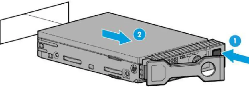
Installing a hot-plug drive
WARNING: To reduce the risk of injury from electric shock, do not install more than one drive carrier at a time.
The server can support up to 24 drives in an LFF configuration and up to 48 drives in an SFF configuration. To install the component:
1. Do one of the following:
o For tower models, open and remove the tower bezel (on page 24).
o For rack models, if installed, remove the security bezel (on page 24). 2. Remove the drive blank.