Borosilicate and Fused-Silica Capillary Microelectrode Electrochemical Comparison and Micromanipulator Adaptor for Fused-Silica Capillary Microelectrodes
Devon F. Martin
Department of Chemistry, University of North Carolina, Chapel Hill, NC, 27514 Dates of Experiments: October 2016 to April 2017
In fulfillment of Chem 692H Research Project under Dr. Mark Wightman and supervision of Nathan Rodeberg
Abstract
Borosilicate glass is the material predominately used for encasing carbon fiber (CF) microelectrodes for fast-scan cyclic voltammetry (FSCV) experiments. These capillaries insulate unexposed CF from the surrounding environment, while leaving a 150-200 um exposed CF tip in vivo that allows for electrochemical measurements of neurotransmitters. However, borosilicate glass commonly breaks during implantation; this can leave debris in the rat brain and prevent lowering of subsequent electrodes, reducing experimental yield. Additionally,
borosilicate glass electrodes often contain cracks at the seal, resulting in undesirable
electrochemical characteristics. This can be alleviated with the use of epoxy resin to fill cracks and solidify the seal. Recently, a new design of CF microelectrodes using fused-silica (FS) was announced, which was more flexible and resilient to strain1. This study compares non-epoxied borosilicate, epoxied borosilicate capillary microelectrodes, and FS microelectrodes. The electrochemical characteristics (RMS noise, background amplitude, and background peak locations) between these three designs were compared.
Additionally, the larger diameter of the glass electrodes (600 um compared to 90 um FS) allow them to be used in micromanipulators, which allow for precise control of electrode depth along the dorsal-ventral axis and new electrodes to be used for each experiment. The FS electrodes lack any such device, so an adaptor prototype was developed to match the smaller
diameter; the FS electrode construction process was also adjusted to fit the design. These two experiments make FS a more acceptable and useful electrode for in vivo testing.
Introduction
Fast-scan cyclic voltammetry (FSCV) is an electrochemical detection technique that permits subsecond detection of neurotransmitters in vivo. Because FSCV scans can be taken many times a second (usually 10 per sec), the transient changes in neurotransmitter concentration can be measured on a relevant timescale to animal behavior. A major advantage to FSCV over alternate detection techniques is the small size of the carbon fiber (CF) sensor. CF is an
electrically conductive, small yet sturdy material with a diameter of 5-7 μm. This small size prevents gliosis on the CF tip1 (Figure S1).
Each electrode has a protective casing to control CF exposure: either borosilicate (glass) or FS. Borosilicate glass has been more common because of its extensive characterization and its quick, easy construction process; however, implanting this in the brain for long durations is feasible, as it can break from small perturbations caused by the rat’s behavior post-surgery or from strain caused by the skull cap hardening. Electrodes encased in FS are significantly more flexible, stress-resilient, and are commercially available in diameters of around 90 um1. These properties make FS preferred in long-term (ranging a few months) measurements of
neurotransmission. Before implementing FS electrodes, comparisons need to be made between glass and FS electrode designs to ensure similar electrochemical properties to make sure results with the two designs are comparable. For this experiment, root-mean-square (RMS) noise, background peak amplitude, and the corresponding voltage position (EQH) were compared between each electrode class.
The electrochemical seal is an additional significant difference between the two types of electrodes: the FS seal is created by wicking epoxy resin into the FS capillary, -while the glass seal is produced via heat pulling, which can result in imperfections. Epoxying the seal
afterwards can fill in the cracks seen in glass capillary electrodes. A group comparison was conducted to determine whether the epoxying process for glass electrodes yields any
electrochemical differences compared to non-epoxied borosilicate electrode controls.
Glass electrodes also benefit from micromanipulators which allow the electrode depth along the dorsal-ventral axis to be controlled. These manipulators also allow new glass electrodes to be used for each measurement period and can secure the electrode at a particular depth by locking into a cemented- and therefore stationary- cannula in the headcap. FS electrodes have no such device and must be implanted directly during the initial surgery; its position cannot be adjusted post-surgery and an electrode cannot be replaced should it break. Currently-used micromanipulators lower glass electrodes by 300 μm per rotation, allowing for 75-μm resolution.2 For the latter half of this experiment, an adaptor capable of handling the smaller sized (90-um diameter FS compared to 600-um diameter glass) FS electrodes was designed. Such a device has the potential to replace the brittle glass electrodes with FS ones for repeated measurements and signal optimization in awake animals, while avoiding the concerns for long-term stability of chronic implantations.
With this in mind, the centermost piece of a previously designed metal manipulator consisting of three ridged metal, hollow, commercially-available cylinders, was remodeled. The two outer cylinders have threads that complement each other and move the centermost piece, which houses the electrode, along the dorsal-ventral axis without rotating (Figure S4). This centerpiece was redesigned to be reusable while accommodating the smaller-diameter FS
electrode. New FS electrodes can then be wired into the centerpiece in neurochemical
measurements following cannula placement in the skull cap. This has threefold benefit: it avoids the month-long incubation period, allows for replacement should a FS electrode malfunction, and allows for depth readjustment to reach DA-rich regions along the cannula-set axis. The FS electrode construction process was adjusted to compliment the new manipulator.
Methods and Materials
The processes for the construction of each electrode can be found in supplementary procedures.
Electrode Data Acquisition
Non-epoxied borosilicate glass, epoxied borosilicate glass, and FS electrodes (n = 20 for each group) were constructed. Each electrode was lowered into Tris buffer (pH = 7.4) and the background current was monitored in the program HDCV3. Each electrode was cycled for 30 min at 60 Hz, followed by 30 min at 10 Hz, followed by a recorded 30 sec sample at 10 Hz. Only those with consistent electrical connections and little electrochemical jitter were used. The 30 sec sample was then examined in HDCV Analysis. The background cyclic voltammogram and a background-subtracted current vs. time trace (at 620 mV) were collected for each
electrode. The maximum background current, corresponding peak locations (in volts), and RMS noise were recorded. RMS noise was defined as three times the standard deviation of the
background-subtracted current for the 30 sec period. The fiber and seal lengths were recorded via microscope for each electrode.
Micromanipulator Adaptor Design
The initial metal micromanipulators were Biela microdrives (Crist Instruments Co., Hagerstown, MD). The centerpiece from this design was replaced with two cylindrical halves
and a top ring connected to one of the halves. The design allows for FS electrodes to be placed onto the inner groove of the left half of the adaptor. The right half is placed over the left half to complete the cylinder while leaving a 90-μm diameter whole through the center. It remains stationary to the left half with shrink-wrap and tape placed around the outside, which also increases the diameter of the centerpieces to fit with the Biela microdrive.
The hemispherical pieces were built from 0.06-in diameter extruded acrylic
(ACREXR0.060, ePlastics, San Diego, CA). The rods were cut in half along the axis via laser cutting (VLS6.60, Universal Laser Systems, Scottsdale, AZ). Laser ablation was then used to cut the 90-μm indentions in the centers.
Results
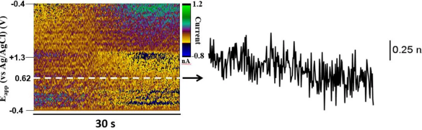
For each group of electrodes, background current peak amplitude (nA), the corresponding voltage (mV), the RMS noise (nA), fiber tip length (μm), and seal length (μm) were compared. The latter two properties were established via microscope. The former three properties were obtained from a 30 sec sample from HDCV following cycling in Tris buffer (pH = 7.4) at 60 Hz for 30 min and 10 Hz for 30 min6. A representative cyclic voltammogram from this process is shown in Figure 1. The maximum current determined the background peak amplitude and corresponding location; noise effects were neglected as their amplitudes were at least two orders of magnitude below that of the background. Noise was measured from the 0.62 V horizon in the color plot (Figure 2) because this is the approximate potential at which DA, the most commonly measured analyte with FSCV, is oxidized7. Once these data were collected for each electrode in a group, linear regression was performed to determine relations between the variables tested. After all groups were obtained, one-way ANOVA was conducted to determine similarities and differences in these properties between electrode designs.
There was no statistically significant relationship between any electrochemical property tested and seal length for borosilicate electrodes, or seal radius in FS electrodes. Exposed fiber length however, showed significant correlation with both background current amplitude and noise levels (Figure 3) for all electrode groups. Although the noise vs fiber length plot for non-epoxied glass electrodes showed non-statistically significant correlations, this plot was included to show the general trend throughout all electrodes.
A one-way ANOVA indicated significant differences between electrode designs in background amplitude, peak location, and noise levels. Tukey’s post hoc test for multiple
Figure 1. Voltammogram Example
After cycling in Tris solution (pH = 7.4), the above voltammogram was taken to determine a) peak background amplitude and b) corresponding potential (EQH) (vs. Ag/AgCl).
Figure 2. Background Subtracted Color Plot and Noise Attainment
Noise measurements were derived from color plots at 0.62 V (shown as white dotted line) over a 30 sec sample period following electrode cycling in Tris (pH = 7.4) for 30 min at 60 Hz and 30 min at 10 Hz.
comparisons showed significant differences between non-epoxied borosilicate and with both epoxied borosilicate and FS for all three variables. However, no statistically significant differences were found between fused silica and epoxied borosilicate for any variable tested (Figure 4). Both electrode types however, differ significantly from non-epoxied glass electrodes in all three electrochemical measurements tested. Taken together, these results indicate
substantial differences between the epoxied capillary electrodes and the non-epoxied ones, with
Figure 3. Regression Plots
(a-c) Correlations between background current vs fiber length for a) non-epoxy glass, b) epoxy glass, and c) FS electrodes. Significant correlations were found for all three groups (p < 0.0001 for all). (d-f) Correlations between noise and fiber length for d) non-epoxy glass, e) epoxy glass, and f) FS electrodes. Significant correlations were found for epoxied glass and FS (p = 0.0477 and p = 0.0327 respectively), but not for non-epoxied glass (p = 0.0613).
no evidence of differences within the epoxied electrode group, suggesting that the FS design may be more electrochemically robust than borosilicate glass electrodes. These differences can however, be controlled for by adding epoxy resin.
Discussion
Electrochemical Comparisons
Comparison of the electrode designs indicates that epoxide is necessary for proper insulation of the electrode. When the glass electrodes are dipped in an epoxy resin/hardener mixture for 30 sec, the epoxy fills any fractures, thereby preventing solution from entering the capillary. This prevents contact of the brain solution with the encased CF, isolating the signal observed at the protruding CF tip. The FS electrodes are sealed with epoxy beads which are pulled into the capillary. In this way, the front section of the electrode FS capillary is coated with a hemisphere of epoxy, retaining fiber surface area integrity. Moreover, it protects unexposed fiber from the surrounding environment.
Correlation analysis between electrochemical properties and fiber tip length showed the greatest correlation with background amplitude, indicating that CF affects signal amplitude the
Figure 4. ANOVA Tests of Electrochemical Properties between Non-Epoxied Glass, Epoxied Glass, and Fused Silica Electrodes
Non-epoxied glass capillary electrodes differ from epoxied glass capillary electrodes and fused silica electrodes in background amplitude (p < 0.0001 for both), voltage of background peak (p < 0.0001 and p < 0.001 respectively) and RMS noise (p < 0.05 and p < 0.001 respectively). There is no statistically significant difference between epoxied glass and fused-silica capillary electrodes in any of the three properties tested.
greatest; seal length had no correlation with any variable tested. With no statistically significant difference between epoxied glass and FS electrodes, there is no preference for glass capillary electrodes over FS electrodes for measurement purposes.
The greater the area of contact between the CF tip and the solution, the greater the background amplitude and noise (Figure 3). For accurate signaling, it is imperative that all cracks in the capillary be sealed and that unexposed fiber be isolated. Improperly insulated electrodes yield higher peak background amplitudes because of the increased available surface area on the electrically active CF. The potentials of the background peaks were examined because these leaks result in a higher capacitance, and therefore impedance, of these electrodes, which would lead to more positive potential shifts, which have been seen previously5. The significantly more positive potentials for non-epoxy glass indicate that this is likely an issue, and that stray impedance could alter electrochemical measurements.
Manipulator Design
The design of the micromanipulator adaptor had to meet set parameters: it had to be sized to match the original piece (2.5 cm long cylinder with 0.3 cm diameter), required an indention along the outside to align with the rest of the manipulator, had to have a larger-sized top to remain level with the outer cylinder of the manipulator, and needed to consistently hold the 90 to 100-um-diameter FS. With these in mind, the adaptor was designed in two halve pieces (Figures S5 and S6), with all qualifications met using specific geometries. One half was attached to a wide top hollow cylinder to keep the adaptor level with the controllable outside cylinder of the manipulator while allowing a wire to pass through in order to complete the circuit.
The hemispherical inner cylinders have a slight indention in the center, which, when viewed from above, creates a 90-μm diameter hole (Figure S7) through the center of the device, forcing FS alignment. This small size was achieved with laser-precise cuts. The device in total is 2.5 cm tall and matches the diameter of the original adaptor, making it applicable to the original manipulator. The device is reusable since a new electrode can be set in the device by opening and closing the bottom two halves. Once combined, the two halves are held together with a piece of shrink-wrap cut along its axis, which forms the needed indention. The prototype can be seen in Figures S9 and S10. The FS capillary was able to be placed into the mold and remained stationary, indicating proper fitting (Figure S11). The assembly however, proved difficult as the hemispheres had to be aligned by hand and the diameter changed with shrink wrap size; this both prevented the segment from fitting in the manipulator and made procedural reproduction difficult.
To match the adaptor’s requirements, the FS electrode was lengthened to 8.0 cm in order to fit through the manipulator, cannula, and brain (Figure S8). The wire was created solely to connect the FS electrode to the pin to establish an electrical connection for electrochemical experiments. The tip of the FS electrode remains the same in terms of length and epoxying. Another piece of shrink wrap was added around the silver epoxy for insulation.
Conclusion
These two experiments sought to show the validity and ease with which FS capillary electrodes could be used for in vivo experiments. The electrochemical comparison showed that FS electrodes have proper insulation and give background signals similar to the currently-used epoxied glass electrodes. There is no electrochemical advantage to preferring one of these designs over the other. Secondly, problems with chronic implantation of FS electrodes could be
resolved using this newly-designed adaptor for precise control of electrode depth, though optimization in its development process is necessary before being accurate enough for use in experiments. The adaptor is designed to be reusable, allowing new FS electrodes to be used for each measurement experiment while avoiding common fragility seen in borosilicate capillary electrodes.
References
1- Clark, Jeremy J. et al; Chronic microsensors for longitudinal, subsecond dopamine detection in behaving animals; Nature Methods, 2010, 7, 2, 126-129.
2- Wightman et al.; Dopamine release is heterogeneous within microenvironments of the rat nucleus accumbens; European Journal of Neuroscience, 2007, 26, 2046-2054.
3- Bucher et al.; Flexible Software Platform for Fast-Scan Cyclic Voltammetry Data Acquisition and Analysis; Anal. Chem., 2013, 85 (21), 10344-10353.
4- Louilot, M. Buda; F. Gonon; H. Simon, M. Le Moal; J. F. Pujol; Effect of Haloperidol and Sulpiride on Dopamine Metabolism in Nucleus Accumbens and Olfactory Tubercle: A Study by In Vivo Voltammetry; Neuroscience, 1985, 14, 3, 775-782.
5- Meunier, Carl J.; James G. Roberts; Gregory S. McCarty, Leslie A. Sombers; Background Signal as an in Situ Predictor of Dopamine Oxidation Potential: Improving Interpretation of Fast-Scan Cyclic Voltammetry Data; ACS Chem. Neurosci., 2017, 8, 411-419.
6- Rodeberg, Nathan T.; Stefan G. Sandberg; Justin A. Johnson; Paul E. M. Phillips; R. Mark Wightman; Hitchhiker’s Guide to Voltammetry: Acute and Chronic Electrodes for in Vivo Fast-Scan Cyclic Voltammetry; ACS Chem. Neurosci., 2017, 8, 221-234.
7- Heien, Michael L. A. V.; Michael A. Johnson; R. Mark Wightman; Resolving
Neurotransmitters Detected by Fast-Scan Cyclic Voltammetry; Anal. Chem. 2004, 76, 5697-5704.