Available online at www.ijrp.org
International Journal of Research Publications
Conceptual Design Code Validation and Optimization of Aircraft for Minimum Drag and Maximum Range
Banyar Theina, Kyaw Min Tintb
a
Department of Airport Management, Myanmar Aerospace Engineering University Myanmar
b
Department of Propulsion and Flight Vehicles,, Myanmar Aerospace Engineering University Myanmar
Abstract This paper develops conceptual design code and validate with existing results of Single Seat Aerobatic aircraft (SSA) by the user requirements. Special consideration is given to minimize total Drag, maximum Range for optimum conceptual design based on developed design code.
© 2019 Published by IJRP.ORG. Selection and/or peer-review under responsibility of International Journal of Research Publications (IJRP.ORG)
Keywords:Conceptual Design; Validation; Range; Total Drag
Available online at www.ijrp.org
International Journal of Research Publications
Volume-20, Issue-1,January 2019
Accepted and Published Manuscript
Conceptual Design Code Validation and Optimization of Aircraft for Minimum Drag and Maximum
Range
Banyar Thein
PII : Banyar Thein.10020112019483
DOI: 10020112019483
Web: http://ijrp.org/paper-detail/484
To appear in: International Journal of Research Publication (IJRP.ORG)
Received date: 05 Jan 2019
Accepted date: 16 Jan 2019
Published date: 22 Jan 2019
Please cite this article as: Banyar Thein , Conceptual Design Code Validation and Optimization of Aircraft
for Minimum Drag and Maximum Range , International Journal of Research Publication (Volume: 20,
Issue: 1), http://ijrp.org/paper-detail/484
This is a PDF file of an unedited manuscript that has been accepted for publication. As a service to our
customers we are providing this final version of the manuscript.
International Journal of Research Publications
Conceptual Design Code Validation and Optimization of
Aircraft for Minimum Drag and Maximum Range
Banyar Thein
a, Kyaw Min Tint
baDepartment of Airport Management, Myanmar Aerospace Engineering University
Myanmar
bDepartment of Propulsion and Flight Vehicles,, Myanmar Aerospace Engineering University
Myanmar
Abstract
This paper develops conceptual design code and validate with existing results of Single Seat Aerobatic aircraft (SSA) by the user requirements. Special consideration is given to minimize total Drag, maximum Range for optimum conceptual design based on developed design code.
© 2019 Published by IJRP.ORG. Selection and/or peer-review under responsibility of International Journal of Research Publications (IJRP.ORG)
2 Banyar Thein / International Journal of Research Publications (IJRP.ORG)
1.Introduction
Aircraft conceptual design process characterized by a large number of design alternatives and trade-off studies, as well as a continuous change in the aircraft concepts under consideration [1]. The Range is the furthest distance the aircraft can fly without refueling and is larger effect on aircraft takeoff weight [2]. The minimization of total Drag indirectly improves the performance parameters such as Range [3]. So, we need to minimize total Drag.
The Range and the total Drag are largely effect on aircraft design, Therefore, the researcher are optimize the design of aircraft for maximum Range and minimum total Drag.
A researcher who minimize total Drag of VLA by using aircraft layout data as variable [3]. And also optimize aircraft configuration for minimum Drag and maximum Range by the use of optimization MATLAB program, FMINCON 4]. Optimization of Supersonic Business Jet (SSBJ) for maximum Range by using Genetic algorithm [5]. In this research, conceptual design of SSA [1] is developed MATLAB codes to validate. And the codes results are used as baseline to optimum design for minimum total Drag, maximum Range.
2.Conceptual Design
Conceptual design usually begin with a specific design requirement established by the prospective customer [1]. And the conceptual design of SSA [1] is used to develop MATALB code and to validate.
3.Requirements
The SSA need to design cruise Range ≥ 280nm at 115Kts, and maximum velocity of 130Kts, and a stall
velocity of 50Kts.
Take off distance ≥ 1000ft
Rate of climb ≥ 1500 ft/min
Crew weight = 220 lb
The Engine ( LYCOMING O-320-A2B) having Cbhp, specific fuel consumption is assumed 0.5 at cruise speed, revolution of 2700RPM and horse power of 150hp.
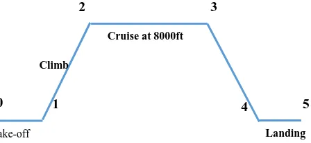
The SSA has to fly with the requirements, and the related mission profile is given in Fig .1.
Fig. 1. Mission profile segments Take-off
Climb
Cruise at 8000ft
Landing
0 1
2 3
4 5
4.Conceptual Design Steps
Hp/W is chosen by the engine. Wing aspect ratio of 6, taper ratio of 0.4, NACA 632015 as root and 632012
as tip are used from the historical data. Horizontal and Vertical tail are used Aspect ratio NACA 0012 and taper ratio of 0.4.
W/S is calculated each mission segments and then selected lowest wing loading. Take-off weight and empty weight are calculated using (1) by iterative process on rubber engine sizing.
W0= (Wcrew+Wpay) / [1- (Wf/W0)-(We/W0)] (1)
After this, the layout design of wing, fuselage, tails, fuel tank, tire size, and propeller diameter are calculated and total Drag is calculated by using
CD = CD0 + K CL2 (2)
Total drag is the sum of parasite drag (CD0) and lift induced drag (K CL2).
CDO= ƩCf (Re, M) (Swet/SRef) + CDmisc+ CDL& P + CDcooling (3)
Parasite drag (CD0) is the total sum of wing, tail, fuselage (ƩCf (Re, M) (Swet/SRef)), leakage and
protuberance drag (CDL&P), nacelle drag, landing gear drag and miscellaneous drag (CDmisc).
K=1 / (π e Aw) (4)
e = 1.78 [ 1- 0.045(Aw)0.68] - 0.64 (5)
CL= (W/S) / (1/2 ρcr Vcr2 ) (6)
Range is calculated at L/D for the cruise condition.
Range= 550 (ηp / Cbhp) (L/D) ln (W3/W2) (7)
Calculation is done by the conceptual design step. And MATLAB codes are developed.
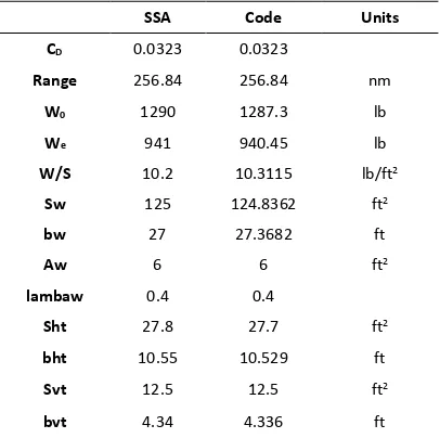
5.Conceptual Design Code Validation
The design codes are developed by the conceptual design steps. And validate with SSA [1] as shown in TABLE I.
4 Banyar Thein / International Journal of Research Publications (IJRP.ORG)
Table 1. Design Code Validation with Existing Data
6.Optimization
The SSA has low Range comparing with requirements from Table I. The minimization of total Drag
indirectly improves the performance parameters such as Range [2]. So, we need to minimize total Drag. So code results are used as baseline and the existing aircraft data are used for upper and lower bounds to optimum design.
6.1.Geometry Selection
For getting optimum design, wing aspect ratio and taper ratio are used as variables.
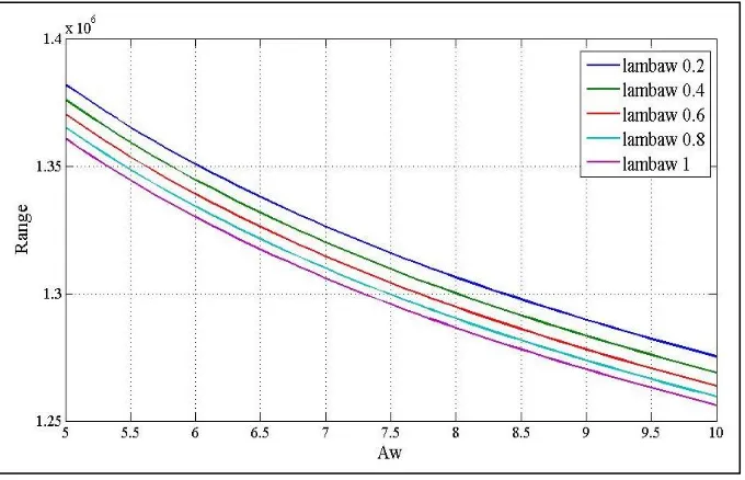
Wing aspect ratio range is between 5 and 10 and taper ratio is from 0.2 to 1. These two variables are chosen for minimum total drag and maximum Range from fig.2 by using (2) and fig.3 by (7). In fig.3 the range is calculated at the cruise condition, means L/D at cruise. For the maximum Range, L/D must use optimum point from drag polar but Fig.3 is plotted for getting the variation of Range and aspect ratio.
From Fig.2, the higher the aspect ratio (Aw), the lower the total Drag (CD) and also the lowest taper ratio (lambaw) give minimum total Drag (CD).
The higher aspect ratio (Aw) give lower Range and the higher taper ratio (lambaw) give higher Range from Fig.3.
Therefore, aspect ratio maximum give lowest total Drag and taper ratio minimum give lowest total Drag and highest Range.
Aw=10, lambaw=0.2 are the optimum for minimum total Drag, and Maximum Range.
SSA Code Units
CD 0.0323 0.0323
Range 256.84 256.84 nm
W0 1290 1287.3 lb
We 941 940.45 lb
W/S 10.2 10.3115 lb/ft2
Sw 125 124.8362 ft2
bw 27 27.3682 ft
Aw 6 6 ft2
lambaw 0.4 0.4
Sht 27.8 27.7 ft2
bht 10.55 10.529 ft
Svt 12.5 12.5 ft2
bvt 4.34 4.336 ft
Fig. 2. Aspect ratio and total Drag with taper ratio
Fig. 3. Aspect ratio and Range with taper ratio
6 Banyar Thein / International Journal of Research Publications (IJRP.ORG)
L/D for optimum design is 12.7. L/D for SSA design is 10.5 from Fig.4. For the maximum Range, calculation is done by (7)
Fig. 4 Drag polar for L/D optimum
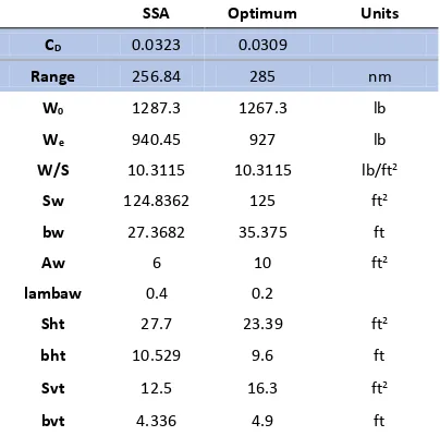
7.Baseline Design and Optimum Design Comparison
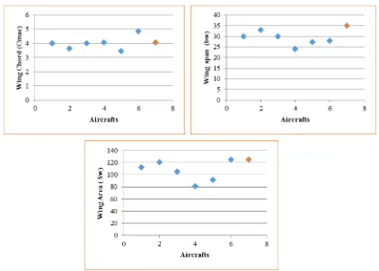
Optimum results are shown in TABLE II, comparing with SSA design code results. Also, the optimized SSA’s wing mapping configuration data are created in Fig.5 to prove that the optimum configuration data are
in the bounds of current SSAs.
Table 2. Design Code Validation with Existing Data
SSA Optimum Units
CD 0.0323 0.0309
Range 256.84 285 nm
W0 1287.3 1267.3 lb
We 940.45 927 lb
W/S 10.3115 10.3115 lb/ft2
Sw 124.8362 125 ft2
bw 27.3682 35.375 ft
Aw 6 10 ft2
lambaw 0.4 0.2
Sht 27.7 23.39 ft2
bht 10.529 9.6 ft
Svt 12.5 16.3 ft2
bvt 4.336 4.9 ft
By the optimum configuration, the total Drag is reduced by 4% and the Range is increased by 11%. The Range is also higher than the required Range of 280 nm, increase about 2%. The total take-off weight and empty weight are also reduced.
From wing mapping Fig.5, the red point is the optimum configuration of SSA,
Fig. 5. Wing Mapping for Optimized SSA configuration
References
[1] Daniel P. Raymer, “Aircraft Design: A Conceptual Approach.”
[2] Thomas C. Corke. Design of Aircraft. Prentice Hall, Pearson Education., Inc; Upper Saddle River. New Jersey 07458. p 109. [3] Nguyen, N. V. (2011). Multidisciplinary configuration design optimization for advanced very light aircraft. The Korean Society
for Aeronautical and Space Sciences, 18-23. http://www.dbpia.co.kr/Article/NODE01839444.
[4] Boone IV, T. R., & Striz, A. G. (2010). Optimization of aircraft configuration for minimum drag. In the proceedings of the 51st AIAA/ASME/ASCE/AHS/ASC Structures, Structural Dynamics, and Materials Conference, Orlando,FL. doi:10.2514/6.2010-3000. [5] Hamza Ashraf, Afreen Abbas, “Conceptual Design and Optimization of Supersonic Business Jet,” Student Research Paper