http://www.sciencepublishinggroup.com/j/ns doi: 10.11648/j.jeee.20180601.15
Foot Trajectory Planning and Optimization Simulation of
Low Foot-Terrain Impact by Quadruped Robot Based on
the Trot Gait
Ma Hui-shu
1, Fang Jian-Jun
21
Beijing Key Laboratory of Information Service Engineering, Beijing Union University, Beijing, China 2
College of Urban Rail Transit and Logistics, Beijing Union University, Beijing, China
Email address:
To cite this article:
Ma Hui-shu, Fang Jian-Jun. Foot Trajectory Planning and Optimization Simulation of Low Foot-Terrain Impact by Quadruped Robot Based on the Trot Gait. Nuclear Science. Vol. 6, No. 1, 2018, pp. 26-30. doi: 10.11648/j.jeee.20180601.15
Received: December 21, 2017; Accepted: February 13, 2018; Published: March 9, 2018
Abstract:
In this essay, I design a bionic quadruped robot driven by a large torque electric cylinder, and establish a kinematics model of it by coordinate transformation. Then I analyze the phase relationship between the one-legged wobble and the supporting phase. For the Trot gait of bionics quadruped robot, an improved algorithm of foot trajectory planning with low force and low energy consumption is proposed. In the gait planning, with the help of kinematic inverse kinematics, the joint function of the leg is solved and the control function of the telescoping capacity of the electric cylinder is deduced by geometric relationship. In MATLAB environment, I simulate and analyze the gait and energy consumption, and carry out the servo control of each leg of the experimental prototype to realize the walking of Trot gait robot with bionic quadruped robot. The simulation results show that the trajectory planning can achieve the continuous and steady walking of the bionic quadruped robot driven by the electric cylinder. Moreover, the trajectory of the foot is smooth, the torso is small, which proves the effectiveness and rationality of the method.Keywords:
Component, Formatting, Quadruped Robot, Trajectory Planning, Zero Impact Algorithm, MATLAB Simulation Analysis1. Introduction
Compared with the wheeled robot, the foot robot is more flexible and adaptable to the unstructured environment and the complex terrain in the field, and thus become a hot spot in the robot research field. In the family of foot robots, quadruped robots are superior to biped robots in stability and load capacity, and their structure and control complexity are outstripped by that of hexapods and eight-legged robots. Therefore, quadruped robots have better overall performance. In the 1980s, Raibert [1] accomplishes the running and jumping behaviors of single-footed, bipedal and quadrupedal robots through analyzing the mechanical characteristics of spring-loaded inverted pendulums. Then various four-legged robots appear. [2-4] The most famous four-legged robot worldwide is BigDog and Cheetah developed by Boston Dynamics. [5-6] Whether a quadruped robot can walk steadily in an unknown environment is a key factor in
judging the intelligent movement ability of it. Therefore, domestic and foreign scholars have carried out in-depth research on the robot gait movement planning.
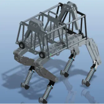
2. Quadruped Bionic Robot
Figure 1. Four-dimensional robot 3D design model.
3. Kinematics Simulation and Analysis
Taking the front right leg (RF) of quadruped robot shown in Figure 1 as an example, I establish the equations of motion of a foot end point in a rectangular coordinate system (world
coordinate system) with the origin of the robot body center. Joint rotation angle and the corresponding relationship between the push rod travel can be deduced through geometrical relationship, which enables the analysis of a leg on kinematics emulation. Thus, I establish the coordinate system for quadrilateral bionic robot as shown in Figure 2 (It only shows RF legs as other legs are similar). Taking the centroid or centroid of the torso of the bionic robot as the origin of coordinates, the advancing direction of the robot as the positive x-axis direction, and the longitudinal direction as the positive y-axis. According to the right-hand rule, the z-axis can be determined. Then I establish the world coordinate system {W}, trunk coordinate system {B}, and foot end coordinate system {E}. Taking the RF leg as an example, the equation of motion of the foot end point P in the trunk coordinate system can be obtained by coordinate transformation.
Considering the complexity of the D-H method and the structural peculiarity of the quadruped bionic robot, the coordinate transformation established by the geometric relation of the plane connecting rod can apply directly to the Oxy sagittal plane, as shown in Figure 3.
Figrue 2. Quadruped bionic robot's coordinate system.
Figure 3. Linkage coordinate system in Oxy plane.
The relationship between the coordinates of the foot end
point P and the joint angle sum can be deduced from the geometric relationship between the connecting rods. According to that relation, given the coordinates of the foot end point P, the joint angle can be inversely calculated. According to the structural design and the geometry of the electric cylinder, the relationship between the telescopic displacement of the electric cylinder and the joint angle can be obtained by using the geometric relationship.
− − −
− −
=
2 1
1 2 1
1 2 1
) sin( sin
) cos( cos
l l y
x
θ θ θ
θ θ θ
According to the formula (1), I use MATLAB software to simulate the relationship between the amount of expansion and displacement, as shown in Figure 4.
Figure 4. Relationship between telescopic displacement of electric cylinder and joint angle.
4. Trajectory Planning
Figure 5. Walking gait timing diagram.
During gait walking, the four-legged robot switches back and forth between the supporting phase and the wobbling phase with the fluctuation of the body. Specifically, the supporting phase refers to the continuous phase change process of the legs during the period from the landing of a leg and its next lift. The wobbling phase is the phase change of the leg from the foot end of the leg to the ground and the fall of the leg after the step process. To ensure the robot's ability to adapt to complex terrains, I adopt the walking gait. The forward speed is lower, but the stability is better, making the robot more adaptable to obstacles and uneven terrain. Its swing legs timings are from the left front - right rear - right front - left, as shown in Figure 5. Among them, the black part is the support phase, and the white part is the wobble phase. The supporting phase carries the robot's load and moves the body of the robot by the phase change of the leg, thus completing the movement of the target in a phase shifted from the Anterior extreme position (AEP) to the posterior extreme position PEP). The wobble phase is from PEP to AEP. It determines the size of the robot's stride and the height of the leg when crossing the obstacle. Therefore, the gait planning pays more attention to the planning of the wobble
phase.
5. Improvement of Zero Shock Gait
Planning Algorithm for Foot
Reference [7], respectively, compares the energy consumption of these three foot trajectories: cycloidal trajectory, sine trajectory, linear trajectory. It demonstrates that the sinusoidal trajectory has the smallest energy consumption in the same step height, step distance. Trajectory functions are as follows:
1 sin 2 2
1 1
cos 2 2 2
t t
x S
T T
t
y H
T
= − π π
= − π
(2)
S is the stride; H is the leg height; is the wobble period; t is the time.
The vertical displacement function [8] given by the above formula shows an acceleration jump at t = 0, t =T, and a larger contact force is required at the moment of raising the leg. To deal with it, this paper modifies the y-direction displacement equation. I design the trajectory equation that when t = 0 and t = T, the x-direction velocity and acceleration are zero with coordinates of 2
s
− (PEP) and 2 s
− (AEP),
respectively.
1 sin 2
2 2
= − π π −
t t S
x S
T T (3)
After the function of y direction is integrated, the speed function is obtained:
1 cos
= π − π +
ɺ AT t
y n c
n T (4)
According to the speed requirement:
0
0, 0
t t T
y y
= = = =
ɺ ɺ
Then
1
AT C
nπ
= , n=2k k=1, 2,…
When n = 2, the foot trajectory will be a diagonal line in the Oxy plane, which is not conducive to the obstacle leap; When n is over the General Assembly, the y direction of the foot frequently accelerates and decelerates, resulting an increase in the system energy consumption. After deliberate consideration, I put n = 4, thus there:
1 cos 4 4
AT t
y
T
π π
= −
ɺ (5)
2
4 sin
4 4
AT
T
n
y
t
C
T
π
π
π
= − +
(6)
Required by trajectory
0
2
0
,
,
0
T
t t tT
y
y
H
y
=
=
==
==
ɺ
ɺ
ɺ
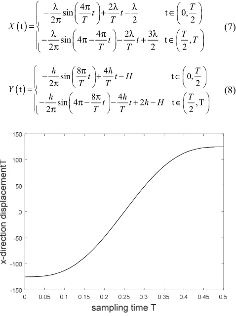
The obtained over determined equation couldn’t find the unknown A and C2. Adopting piecewise function method, I obtain the y-direction motion curve equation as follows:
( )
4 2
sin t 0,
2 2 2
t
4 2 3
sin 4 t ,
2 2 2
T
t t
T T
X
T
t t T
T T
λ π λ λ
− + − ∈
π
=
λ π λ λ
− π − − + ∈
π
(7)
( )
8 4
sin t 0,
2 2
t
8 4
sin 4 2 t , T
2 2
h h T
t t H
T T
Y
h h T
t t h H
T T π − + − ∈ π = π
− π − − + − ∈
π
(8)
Figure 6. X displacement and time relationship.
Figure 7. Y displacement and time.
Figure 8. Diagonal gait planning.
Let S = 500mm, H = 200mm, T = 0.5s, Thorough MATLAB simulation, I get Figure 6 according to formula (3), which describes x displacement and time relationship; Then I get Figure 7 according to formula (7), which describes y displacement and time; Lastly, I get Figure 8 according to formulas (3) and (7), which describes Diagonal gait planning.
The quadruped mammalian gait refers to the regularity of the order and manner of the legs during the exercise. [12] The typical gait mainly consists of the steps of walking, trot, pace and sprint gallop [10]. Compared with other gait, trot gait has higher energy efficiency and greater speed adaptation range. Put gait cycle as T, then the support phase cycle is g
T
, and the one-leg cycle is iT ,
i g
T =T +T . To adapt to the hip joint coordinate system x Axis direction of motion function [11], the time period of processing
(
)
modi i i
T = t +ϕ T (9)
Where t is the system time, i
T
is the trajectory planning time of i-th leg, and the definition of LF foot-end PEP point is 0 moment. To improve the adaptability of unstructured robot, set tort gait cycle as followsTable 1. Quadruped robot trot gait each leg phase table。 Each leg number Phase
LF 0 1
LH 1 0
RH 0 1
RF 1 0
"0" indicates the wobble phase and "1" indicates the supporting phase。
6. Conclusion
My ideas for further research: First, this article only applies the improved algorithm to one leg and conducts simulation verification for it, so I will try to apply that algorithm in four legs in the future. Second, fully considering the robot dynamics issues and the location of the center of
0 0.05 0.1 0.15 0.2 0.25 0.3 0.35 0.4 0.45 0.5
sampling time T -20 0 20 40 60 80 100 y -d ir e ct io n d isp la ce m e n t
-100 -50 0 50 100
mass, I intend to extend the algorithm to all joints of the prototype to further improve the robustness and stability of the algorithm. Then, the feasibility of joint simulation will be verified with the help of MATLAB and ADAMS. Finally, I will carry out experiments on physical ontology to determine the feasibility and effectiveness of the algorithm.
References
[1] Wang Lipeng, Wang Junzheng, Wang Shukun, et al. Status control strategy of hydraulic four-footed robot based on foot-end trajectory planning algorithm [J]. Proceeding of the CSEE, 2013, 49 (1): 39~44.
[2] Raibert M H, Chepponis M, Brown Jr H B. Running on four legs as though they were one [J]. IEEE Journal of Robotics and Automation, 2016, 2 (2): 70~82.
[3] Fukuoka Y, Kimura H, Hada Y, et al. Adaptive dynamic walking of a quadruped robot ‘Tekken’ on irregular terrain using a neural system model. [C]// IEEE International Conference on Robotics and Automation, 14-19 September 2003, Taipei, Taiwan, China. Piscataway, NJ, USA: IEEE, 2013: 2037~2042.
[4] Semini C, Tsagarakis N G, Guglielmino E, et al. Design of HyQ -A hydraulically and electrically actuated quadruped robot [J]. Proceedings of the Institution of Mechanical Engineers Part I Journal of Systems & Control Engineering, 2011, 225:831-849.
[5] Raibert M, Blankespoor K, Nelson G, et al. Bigdog, the rough-terrain quadruped robot. [C]// 17th World Congress,
International Federation of Automatic Control (IFAC), Seoul, Republic of Korea, 6-11 July 2008, Proceedings. IFAC, 2008: 10822~10825.
[6] Playter R, Blankespoor K, Bondaryk J, et al. Building man & beast at Boston Dynamics. [C]// AUVSI Unmanned Systems North America Conference, Las Vegas, NV, the United States, 6-9 August 2012, Proceedings. AUVSI, 2012:1041-1046. [7] Research on trajectory planning and mobile energy
consumption of quadruped robot [J]. Mechanical Design and Research, 2014, 30 (1): 29-34.
[8] Zhang Guoteng, Rong Xuewen, Li Yibin, et al. Status control of diagonal trotters in quadruped robot based on virtual model [J]. Botman, 2016 (1): 64-74.
[9] HE Dong-qing, MA Pei-sun. Analysis of Dynamic Walking Simulation and Walking Stability of Quadruped Robot [J]. Computer Simulation, 2005, 22 (2): 146-149.
[10] Wang Shoukun, Zong Xiaoyan, Chen Guangrong. Research on Energy Consumption of Hydraulic 4-footed Robot Based on Diagonal Gait [J]. Journal of Beijing Institute of Technology, 2016, 36 (4): 399-404.
[11] ZHANG Rui-lei, LI Sheng, CHEN Qing-wei, et al. Multi-robot formation control in complex terrain [J] Journal of Control Theory and Applications, 2014, 31 (4): 531-537. [12] Dai O, Ishiguro A. A Quadruped Robot Exhibiting
Spontaneous Gait Transitions from Walking to Trotting to Galloping: [J]. Scientific Reports, 2017, 7 (1):277.